2005 NISSAN NAVARA wheel size
[x] Cancel search: wheel sizePage 559 of 3171
TROUBLE DIAGNOSIS
AV-71
C
D
E
F
G
H
I
J
L
MA
B
AV
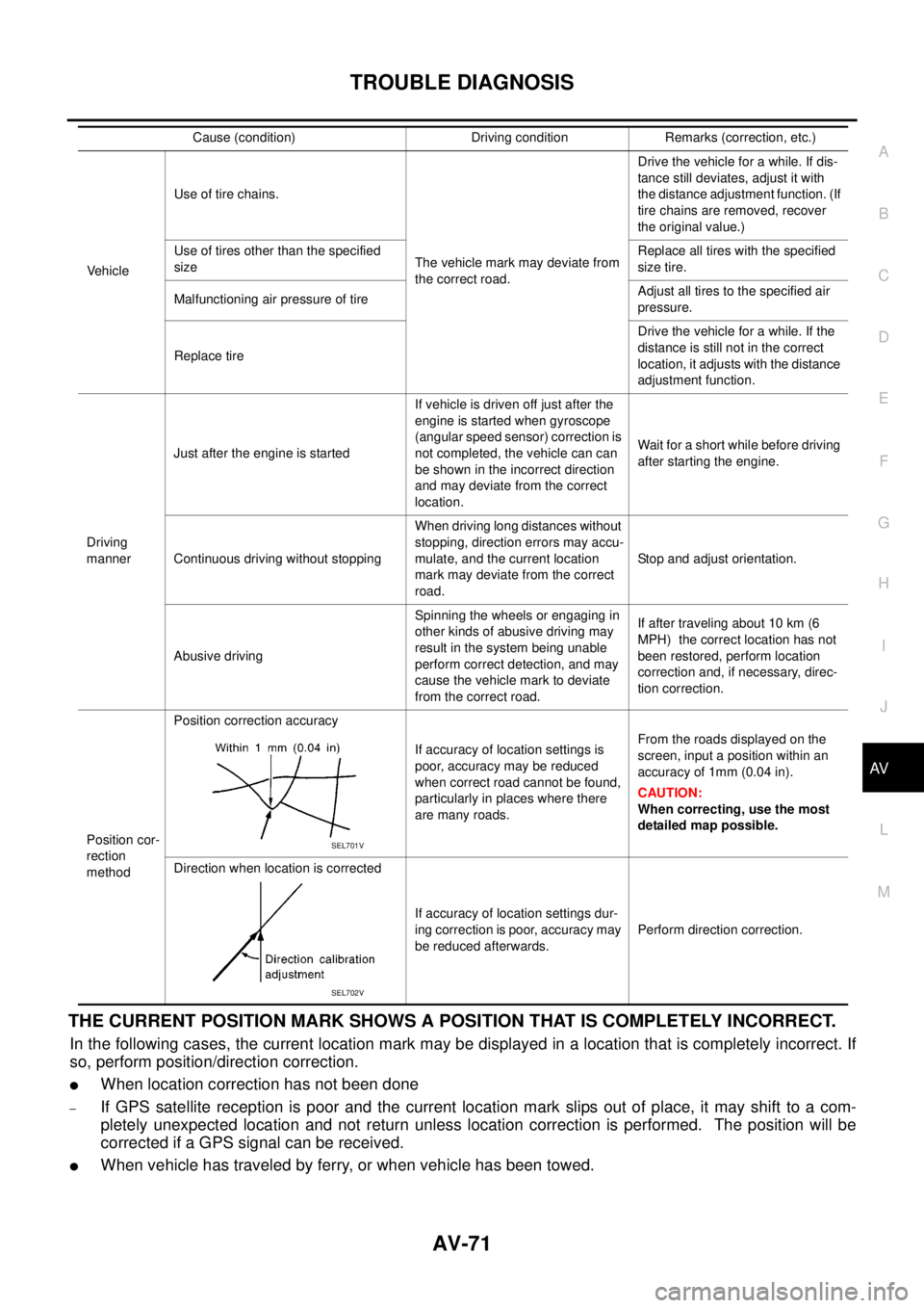
THE CURRENT POSITION MARK SHOWS A POSITION THAT IS COMPLETELY INCORRECT.
In the following cases, the current location mark may be displayed in a location that is completely incorrect. If
so, perform position/direction correction.
lWhen location correction has not been done
–If GPS satellite reception is poor and the current location mark slips out of place, it may shift to a com-
pletely unexpected location and not return unless location correction is performed. The position will be
corrected if a GPS signal can be received.
lWhen vehicle has traveled by ferry, or when vehicle has been towed.
VehicleUse of tire chains.
The vehicle mark may deviate from
the correct road.Drivethevehicleforawhile.Ifdis-
tance still deviates, adjust it with
the distance adjustment function. (If
tire chains are removed, recover
the original value.)
Use of tires other than the specified
sizeReplace all tires with the specified
size tire.
Malfunctioning air pressure of tireAdjust all tires to the specified air
pressure.
Replace tireDrive the vehicle for a while. If the
distance is still not in the correct
location, it adjusts with the distance
adjustment function.
Driving
mannerJust after the engine is startedIf vehicle is driven off just after the
engine is started when gyroscope
(angular speed sensor) correction is
not completed, the vehicle can can
be shown in the incorrect direction
and may deviate from the correct
location.Wait for a short while before driving
after starting the engine.
Continuous driving without stoppingWhen driving long distances without
stopping, direction errors may accu-
mulate, and the current location
mark may deviate from the correct
road.Stop and adjust orientation.
Abusive drivingSpinning the wheels or engaging in
other kinds of abusive driving may
result in the system being unable
perform correct detection, and may
cause the vehicle mark to deviate
from the correct road.If after traveling about 10 km (6
MPH) the correct location has not
been restored, perform location
correction and, if necessary, direc-
tion correction.
Position cor-
rection
methodPosition correction accuracy
If accuracy of location settings is
poor, accuracy may be reduced
when correct road cannot be found,
particularly in places where there
are many roads.From the roads displayed on the
screen, input a position within an
accuracy of 1mm (0.04 in).
CAUTION:
When correcting, use the most
detailed map possible.
Direction when location is corrected
If accuracy of location settings dur-
ing correction is poor, accuracy may
be reduced afterwards.Perform direction correction. Cause (condition) Driving condition Remarks (correction, etc.)
SEL701V
SEL702V
Page 846 of 3171
![NISSAN NAVARA 2005 Repair Workshop Manual BRC-24
[ABS]
TROUBLE DIAGNOSIS
BASIC INSPECTION 3 ABS WARNING LAMP AND BRAKE WARNING LAMP INSPECTION
ON and OFF Timing for ABS Warning Lamp, Brake Warning Lamp
´:ON –:OFF
Note 1:Brake warning lamp NISSAN NAVARA 2005 Repair Workshop Manual BRC-24
[ABS]
TROUBLE DIAGNOSIS
BASIC INSPECTION 3 ABS WARNING LAMP AND BRAKE WARNING LAMP INSPECTION
ON and OFF Timing for ABS Warning Lamp, Brake Warning Lamp
´:ON –:OFF
Note 1:Brake warning lamp](/manual-img/5/57362/w960_57362-845.png)
BRC-24
[ABS]
TROUBLE DIAGNOSIS
BASIC INSPECTION 3 ABS WARNING LAMP AND BRAKE WARNING LAMP INSPECTION
ON and OFF Timing for ABS Warning Lamp, Brake Warning Lamp
´:ON –:OFF
Note 1:Brake warning lamp will turn on in case of operating parking brake (switch turned on) or of a actuating brake fluid level switch
(brake fluid is insufficient).
Note 2:After starting engine, turn OFF.
Check the following items when unsuitable for an above condition.
lABS warning lamp: Refer toBRC-28, "Inspection 4 CAN Communication Circuit".
lBrake waning lamp: Refer toBRC-28, "Inspection 4 CAN Communication Circuit",BRC-30, "Inspection 6
Brake Fluid Level Switch Circuit",BRC-32, "Inspection 7 Parking Brake Switch Circuit".
If malfunction is not found, refer toBRC-33, "
Inspection 8 Warning lamp system".
Inspection 1 Wheel Sensor SystemEFS005TZ
Check each part according to CONSULT-II self-diagnostic results, and then identify the parts to be replaced.
CAUTION:
Check each part between wheel sensor terminals.
INSPECTION PROCEDURE
1.CHECK SELF-DIAGNOSTIC RESULTS
Check self-diagnostic results.
Is above displayed in self-diagnosis display items?
YES >> GO TO 2.
NO >> INSPECTION END
2.CHECK TYRE
Check air pressure, wear and size.
Are air pressure, wear and size within standard values?
YES >> GO TO 3.
NO >> Adjust air pressure, or replace tyre.
Condition ABS warning lampBrake warning lamp
[Note 1]Remarks
Ignition SW OFF – — —
Approx. 2 seconds after ignition
switch is turned ON´´[Note 2] —
Approx. 2 seconds later after ignition
switch ON–´[Note 2]Go out 2 seconds after ignition
switch is turned ON.
ABS error´—There is an ABS actuator and
electric unit (control unit) error.
(Power, ground or system mal-
function)
EBD error´´—
Self-diagnostic results
FR RH SENSOR-1,-2
FR LH SENSOR- 1,-2
RR RH SENSOR-1,-2
RR LH SENSOR-1,- 2
ABS SENSOR [MALFUNCTION SIGNAL]
Page 889 of 3171

OVERHEATING CAUSE ANALYSIS
CO-5
C
D
E
F
G
H
I
J
K
L
MA
CO
Except cool-
ing system
parts mal-
function— Overload on engineAbusive drivingHigh engine rpm under no
load
Driving in low gear for
extended time
Driving at extremely high
speed
Powertrain system mal-
function
— Installed improper size
wheels and tires
Dragging brakes
Improper ignition timing
Blocked or restricted air
flowBlocked bumper —
— Blocked radiator grilleInstalled car brassiere
Mud contamination or
paper clogging
Blocked radiator —
Blocked condenser
Blocked air flow
Installed large fog lamp Symptom Check items
Page 1391 of 3171
PREPARATION
EM-9
C
D
E
F
G
H
I
J
K
L
MA
EM
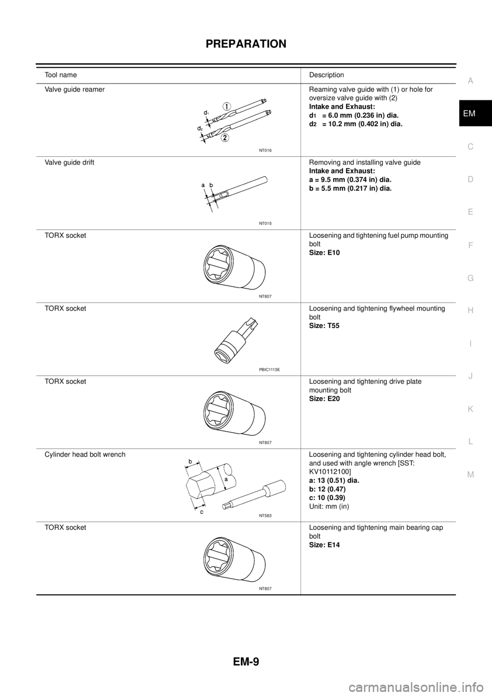
Valve guide reamer Reaming valve guide with (1) or hole for
oversize valve guide with (2)
Intake and Exhaust:
d
1= 6.0 mm (0.236 in) dia.
d
2= 10.2 mm (0.402 in) dia.
Valve guide drift Removing and installing valve guide
Intake and Exhaust:
a = 9.5 mm (0.374 in) dia.
b = 5.5 mm (0.217 in) dia.
TORX socketLoosening and tightening fuel pump mounting
bolt
Size: E10
TORX socketLoosening and tightening flywheel mounting
bolt
Size: T55
TORX socketLoosening and tightening drive plate
mounting bolt
Size: E20
Cylinder head bolt wrench Loosening and tightening cylinder head bolt,
and used with angle wrench [SST:
KV10112100]
a: 13 (0.51) dia.
b: 12 (0.47)
c: 10 (0.39)
Unit: mm (in)
TORX socketLoosening and tightening main bearing cap
bolt
Size: E14 Tool nameDescription
NT016
NT015
NT807
PBIC1113E
NT807
NT583
NT807
Page 1493 of 3171
CYLINDER BLOCK
EM-111
C
D
E
F
G
H
I
J
K
L
MA
EM
lRefer toGI-10, "Components"for symbol marks in the figure.
Disassembly and AssemblyEBS01E6E
DISASSEMBLY
1. Remove engine from the vehicle. Refer toEM-106, "ENGINE ASSEMBLY".
2. Remove clutch cover and disk. (M/T models) Refer toCL-17,
"CLUTCH DISC, CLUTCH COVER AND FLYWHEEL".
3. If they need to be replaced, replace pilot bush (M/T models) or
pilot converter (A/T models).
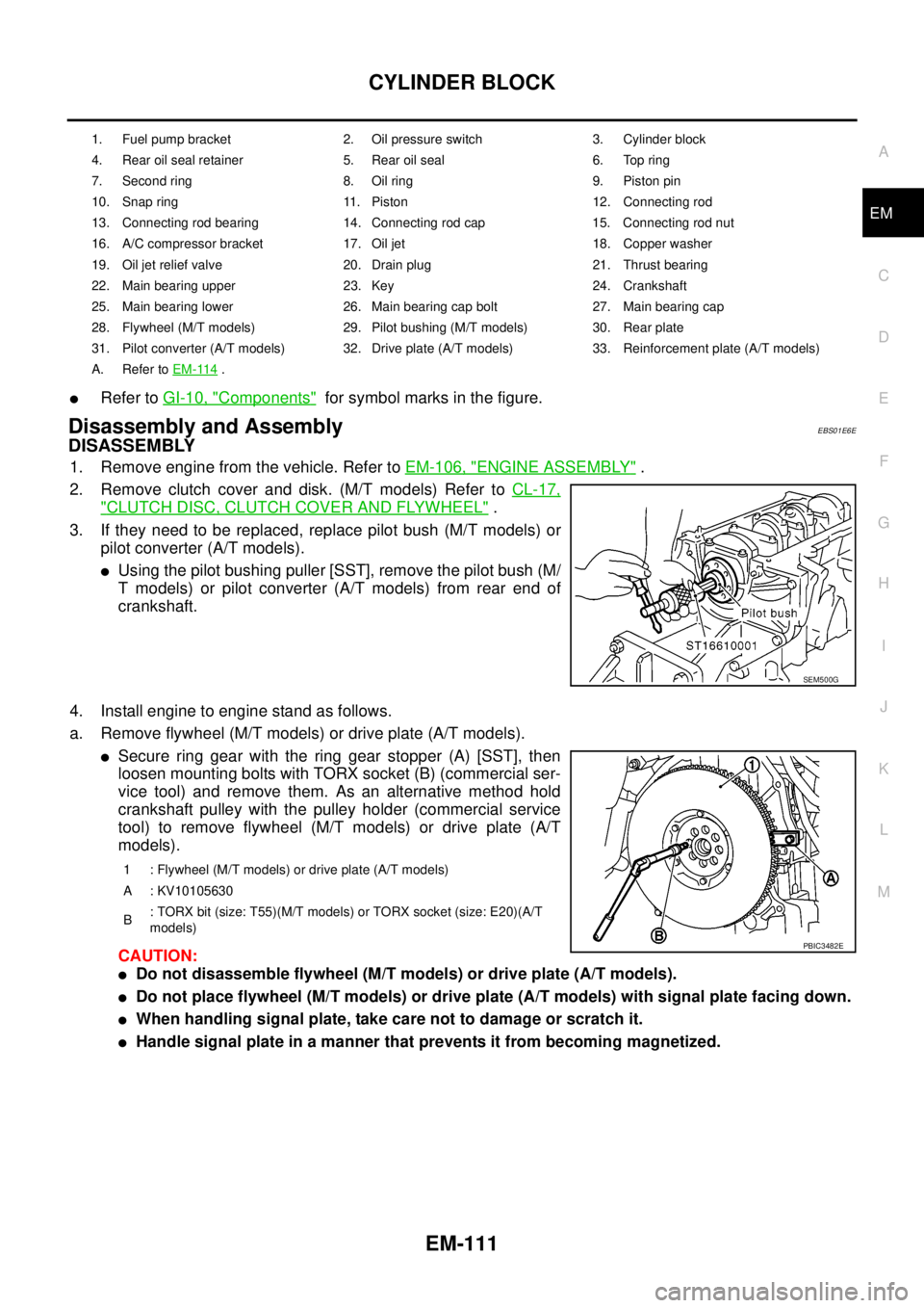
lUsing the pilot bushing puller [SST], remove the pilot bush (M/
T models) or pilot converter (A/T models) from rear end of
crankshaft.
4. Install engine to engine stand as follows.
a. Remove flywheel (M/T models) or drive plate (A/T models).
lSecure ring gear with the ring gear stopper (A) [SST], then
loosen mounting bolts with TORX socket (B) (commercial ser-
vice tool) and remove them. As an alternative method hold
crankshaft pulley with the pulley holder (commercial service
tool) to remove flywheel (M/T models) or drive plate (A/T
models).
CAUTION:
lDo not disassemble flywheel (M/T models) or drive plate (A/T models).
lDo not place flywheel (M/T models) or drive plate (A/T models) with signal plate facing down.
lWhen handling signal plate, take care not to damage or scratch it.
lHandle signal plate in a manner that prevents it from becoming magnetized.
1. Fuel pump bracket 2. Oil pressure switch 3. Cylinder block
4. Rear oil seal retainer 5. Rear oil seal 6. Top ring
7. Second ring 8. Oil ring 9. Piston pin
10. Snap ring 11. Piston 12. Connecting rod
13. Connecting rod bearing 14. Connecting rod cap 15. Connecting rod nut
16. A/C compressor bracket 17. Oil jet 18. Copper washer
19. Oil jet relief valve 20. Drain plug 21. Thrust bearing
22. Main bearing upper 23. Key 24. Crankshaft
25. Main bearing lower 26. Main bearing cap bolt 27. Main bearing cap
28. Flywheel (M/T models) 29. Pilot bushing (M/T models) 30. Rear plate
31. Pilot converter (A/T models) 32. Drive plate (A/T models) 33. Reinforcement plate (A/T models)
A. Refer toEM-114
.
SEM500G
1 : Flywheel (M/T models) or drive plate (A/T models)
A : KV10105630
B: TORX bit (size: T55)(M/T models) or TORX socket (size: E20)(A/T
models)
PBIC3482E
Page 1502 of 3171
EM-120
CYLINDER BLOCK
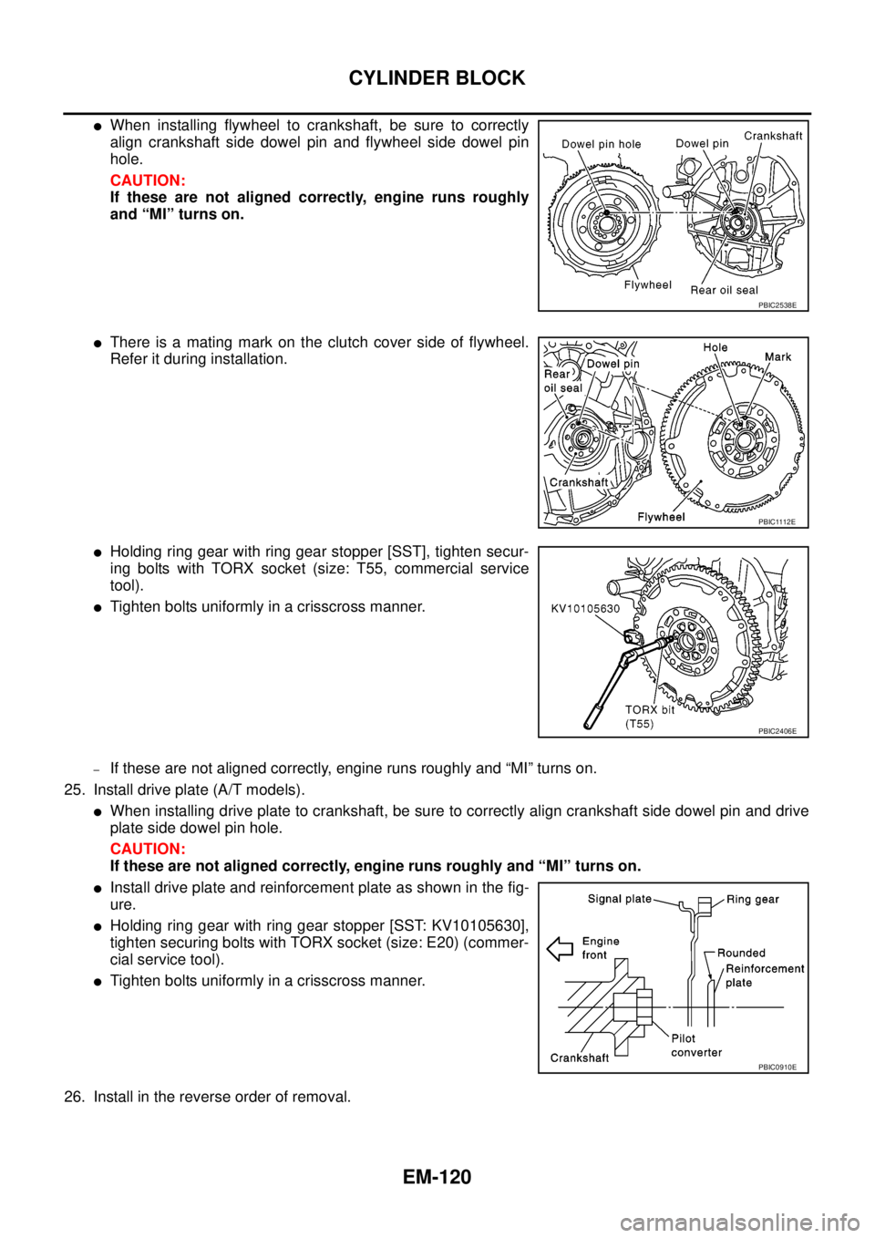
lWhen installing flywheel to crankshaft, be sure to correctly
align crankshaft side dowel pin and flywheel side dowel pin
hole.
CAUTION:
If these are not aligned correctly, engine runs roughly
and “MI” turns on.
lThere is a mating mark on the clutch cover side of flywheel.
Refer it during installation.
lHolding ring gear with ring gear stopper [SST], tighten secur-
ing bolts with TORX socket (size: T55, commercial service
tool).
lTighten bolts uniformly in a crisscross manner.
–If these are not aligned correctly, engine runs roughly and “MI” turns on.
25. Install drive plate (A/T models).
lWhen installing drive plate to crankshaft, be sure to correctly align crankshaft side dowel pin and drive
plate side dowel pin hole.
CAUTION:
If these are not aligned correctly, engine runs roughly and “MI” turns on.
lInstall drive plate and reinforcement plate as shown in the fig-
ure.
lHolding ring gear with ring gear stopper [SST: KV10105630],
tighten securing bolts with TORX socket (size: E20) (commer-
cial service tool).
lTighten bolts uniformly in a crisscross manner.
26. Install in the reverse order of removal.
PBIC2538E
PBIC1112E
PBIC2406E
PBIC0910E
Page 1527 of 3171
SERVICE DATA AND SPECIFICATIONS (SDS)
EM-145
C
D
E
F
G
H
I
J
K
L
MA
EM
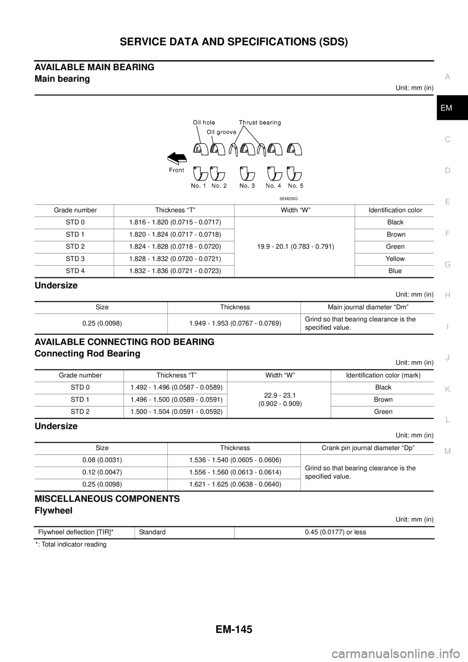
AVAILABLE MAIN BEARING
Main bearing
Unit: mm (in)
Undersize
Unit: mm (in)
AVAILABLE CONNECTING ROD BEARING
Connecting Rod Bearing
Unit: mm (in)
Undersize
Unit: mm (in)
MISCELLANEOUS COMPONENTS
Flywheel
Unit: mm (in)
*: Total indicator readingGrade number Thickness “T” Width “W” Identification color
STD 0 1.816 - 1.820 (0.0715 - 0.0717)
19.9 - 20.1 (0.783 - 0.791)Black
STD 1 1.820 - 1.824 (0.0717 - 0.0718) Brown
STD 2 1.824 - 1.828 (0.0718 - 0.0720) Green
STD 3 1.828 - 1.832 (0.0720 - 0.0721) Yellow
STD 4 1.832 - 1.836 (0.0721 - 0.0723) Blue
SEM255G
Size Thickness Main journal diameter “Dm”
0.25 (0.0098) 1.949 - 1.953 (0.0767 - 0.0769)Grind so that bearing clearance is the
specified value.
Grade number Thickness “T” Width “W” Identification color (mark)
STD 0 1.492 - 1.496 (0.0587 - 0.0589)
22.9 - 23.1
(0.902 - 0.909)Black
STD 1 1.496 - 1.500 (0.0589 - 0.0591) Brown
STD 2 1.500 - 1.504 (0.0591 - 0.0592) Green
Size Thickness Crank pin journal diameter “Dp”
0.08 (0.0031) 1.536 - 1.540 (0.0605 - 0.0606)
Grind so that bearing clearance is the
specified value. 0.12 (0.0047) 1.556 - 1.560 (0.0613 - 0.0614)
0.25 (0.0098) 1.621 - 1.625 (0.0638 - 0.0640)
Flywheel deflection [TIR]* Standard 0.45 (0.0177) or less
Page 1621 of 3171
SERVICE DATA AND SPECIFICATIONS (SDS)
FSU-21
C
D
F
G
H
I
J
K
L
MA
B
FSU
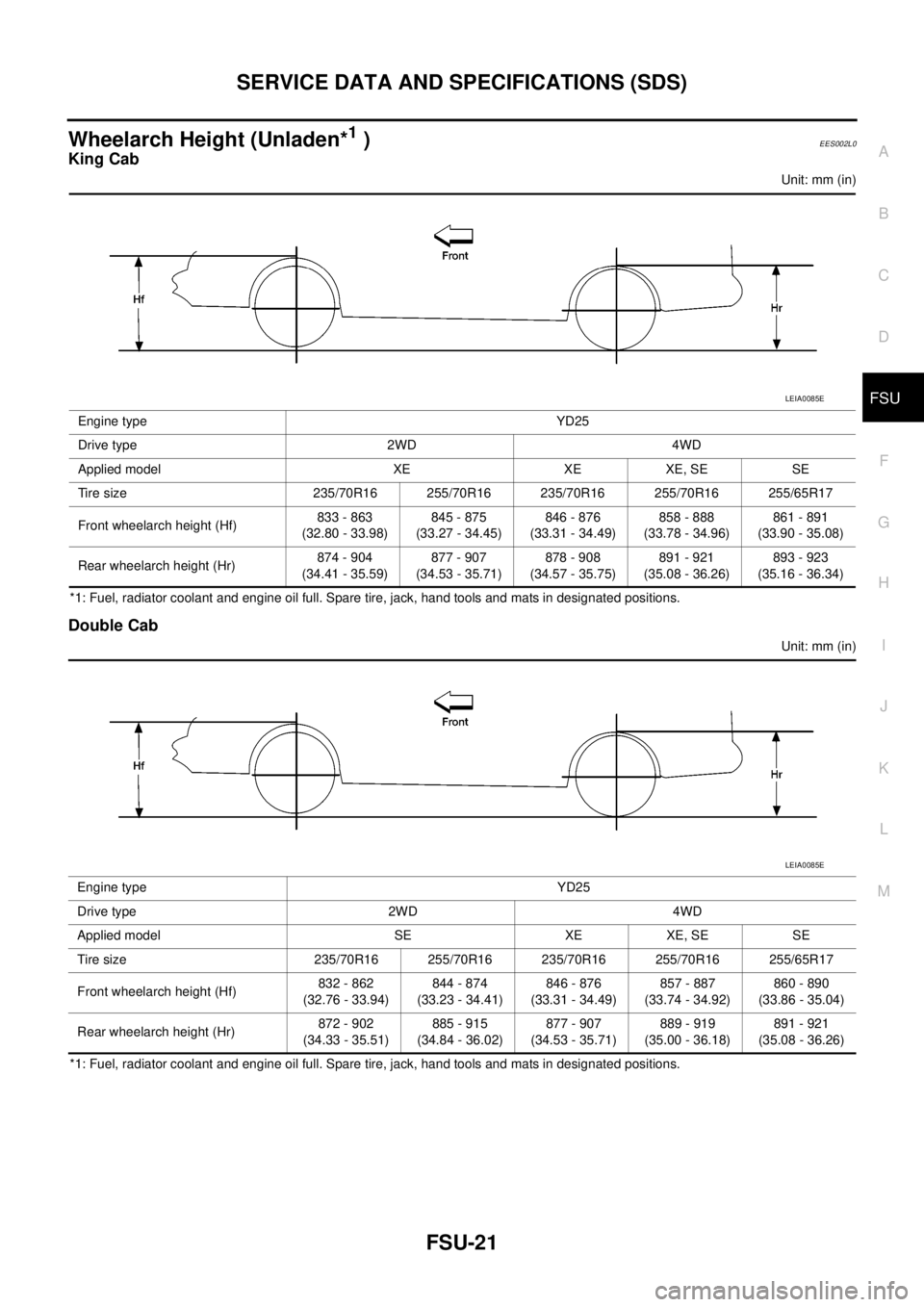
Wheelarch Height (Unladen*1)EES002L0
King Cab
Unit: mm (in)
*1: Fuel, radiator coolant and engine oil full. Spare tire, jack, hand tools and mats in designated positions.
Double Cab
Unit: mm (in)
*1: Fuel, radiator coolant and engine oil full. Spare tire, jack, hand tools and mats in designated positions.Engine type YD25
Drive type 2WD 4WD
Applied model XE XE XE, SE SE
Tire size 235/70R16 255/70R16 235/70R16 255/70R16 255/65R17
Front wheelarch height (Hf)833 - 863
(32.80 - 33.98)845 - 875
(33.27 - 34.45)846 - 876
(33.31 - 34.49)858 - 888
(33.78 - 34.96)861 - 891
(33.90 - 35.08)
Rear wheelarch height (Hr)874 - 904
(34.41 - 35.59)877 - 907
(34.53 - 35.71)878 - 908
(34.57 - 35.75)891 - 921
(35.08 - 36.26)893 - 923
(35.16 - 36.34)
LEIA0085E
Engine type YD25
Drive type 2WD 4WD
Applied model SE XE XE, SE SE
Tire size 235/70R16 255/70R16 235/70R16 255/70R16 255/65R17
Front wheelarch height (Hf)832 - 862
(32.76 - 33.94)844 - 874
(33.23 - 34.41)846 - 876
(33.31 - 34.49)857 - 887
(33.74 - 34.92)860 - 890
(33.86 - 35.04)
Rear wheelarch height (Hr)872 - 902
(34.33 - 35.51)885 - 915
(34.84 - 36.02)877 - 907
(34.53 - 35.71)889 - 919
(35.00 - 36.18)891 - 921
(35.08 - 36.26)
LEIA0085E