2005 NISSAN NAVARA oil filter
[x] Cancel search: oil filterPage 1429 of 3171
INJECTION TUBE AND FUEL INJECTOR
EM-47
C
D
E
F
G
H
I
J
K
L
MA
EM
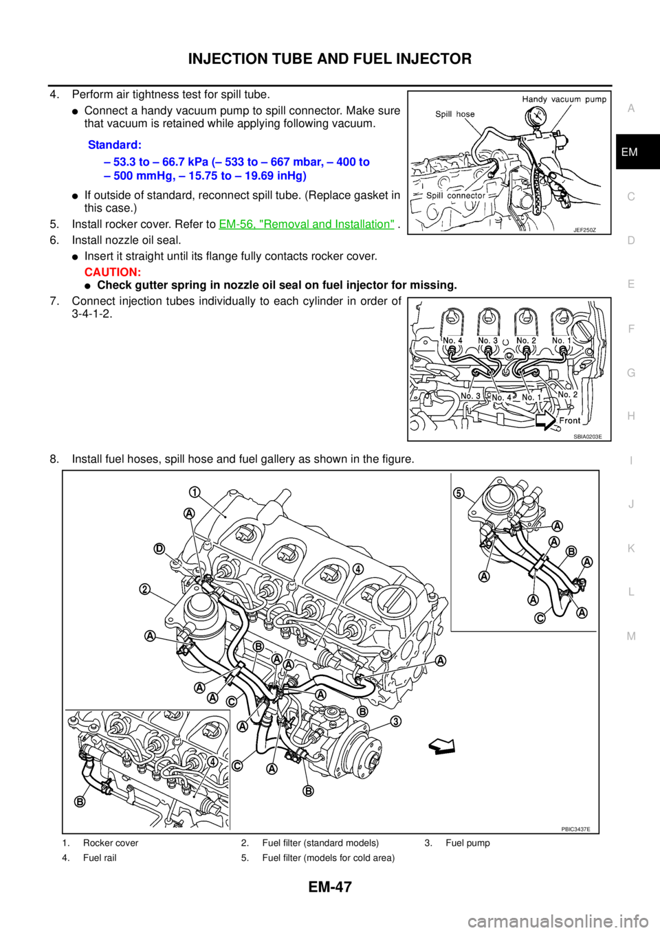
4. Perform air tightness test for spill tube.
lConnect a handy vacuum pump to spill connector. Make sure
that vacuum is retained while applying following vacuum.
lIf outside of standard, reconnect spill tube. (Replace gasket in
this case.)
5. Install rocker cover. Refer toEM-56, "
Removal and Installation".
6. Install nozzle oil seal.
lInsert it straight until its flange fully contacts rocker cover.
CAUTION:
lCheck gutter spring in nozzle oil seal on fuel injector for missing.
7. Connect injection tubes individually to each cylinder in order of
3-4-1-2.
8. Install fuel hoses, spill hose and fuel gallery as shown in the figure.Standard:
–53.3to–66.7kPa(–533to–667mbar,–400to
– 500 mmHg, – 15.75 to – 19.69 inHg)
JEF250Z
SBIA0203E
1. Rocker cover 2. Fuel filter (standard models) 3. Fuel pump
4. Fuel rail 5. Fuel filter (models for cold area)
PBIC3437E
Page 1478 of 3171
EM-96
CYLINDER HEAD
INSTALLATION
Before installation, remove old liquid gasket from mating surface of all liquid gasket applied parts.
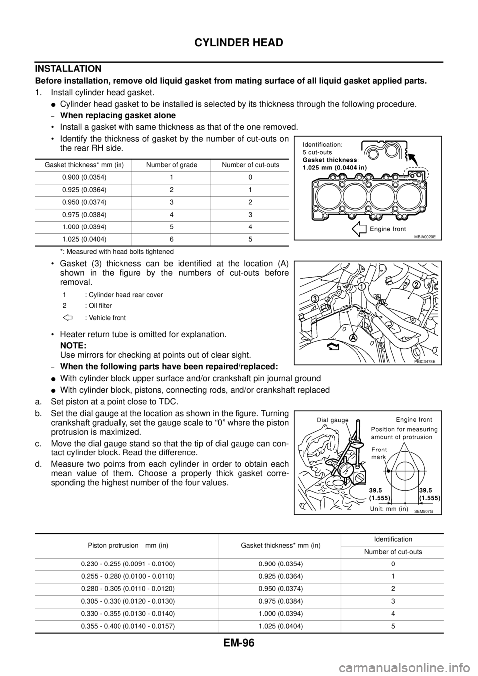
1. Install cylinder head gasket.
lCylinder head gasket to be installed is selected by its thickness through the following procedure.
–When replacing gasket alone
• Install a gasket with same thickness as that of the one removed.
• Identify the thickness of gasket by the number of cut-outs on
the rear RH side.
*: Measured with head bolts tightened
• Gasket (3) thickness can be identified at the location (A)
shown in the figure by the numbers of cut-outs before
removal.
• Heater return tube is omitted for explanation.
NOTE:
Use mirrors for checking at points out of clear sight.
–When the following parts have been repaired/replaced:
lWith cylinder block upper surface and/or crankshaft pin journal ground
lWith cylinder block, pistons, connecting rods, and/or crankshaft replaced
a. Set piston at a point close to TDC.
b. Set the dial gauge at the location as shown in the figure. Turning
crankshaft gradually, set the gauge scale to “0” where the piston
protrusion is maximized.
c. Movethedialgaugestandsothatthetipofdialgaugecancon-
tact cylinder block. Read the difference.
d. Measure two points from each cylinder in order to obtain each
mean value of them. Choose a properly thick gasket corre-
sponding the highest number of the four values.
Gasket thickness* mm (in) Number of grade Number of cut-outs
0.900 (0.0354) 1 0
0.925 (0.0364) 2 1
0.950 (0.0374) 3 2
0.975 (0.0384) 4 3
1.000 (0.0394) 5 4
1.025 (0.0404) 6 5
1 : Cylinder head rear cover
2:Oilfilter
: Vehicle front
MBIA0020E
PBIC3478E
SEM507G
Piston protrusion mm (in) Gasket thickness* mm (in)Identification
Number of cut-outs
0.230 - 0.255 (0.0091 - 0.0100) 0.900 (0.0354) 0
0.255 - 0.280 (0.0100 - 0.0110) 0.925 (0.0364) 1
0.280 - 0.305 (0.0110 - 0.0120) 0.950 (0.0374) 2
0.305 - 0.330 (0.0120 - 0.0130) 0.975 (0.0384) 3
0.330 - 0.355 (0.0130 - 0.0140) 1.000 (0.0394) 4
0.355 - 0.400 (0.0140 - 0.0157) 1.025 (0.0404) 5
Page 1630 of 3171

GI-8
PRECAUTIONS
lWhere there is a risk of eye contact, eye protection should be worn, for example, chemical goggles or face
shields; in addition an eye wash facility should be provided.
ENVIRONMENTAL PROTECTION PRECAUTIONS
Dispose of used oil and used oil filters through authorized waste disposal contractors to licensed waste dis-
posal sites, or to the waste oil reclamation trade. If in doubt, contact the local authority for advice on disposal
facilities.
It is illegal to pour used oil on to the ground, down sewers or drains, or into water sources.
The regulations concerning pollution vary between regions.
Precautions for Air ConditioningEAS001GR
Use an approved refrigerant recovery unit any time the air conditioning system must be discharged. Refer to
ATC/MTC section “HFC-134a (R-134a) Service Procedure”, “REFRIGERANT LINES” for specific instructions.
Page 1754 of 3171
IDX-2
ALPHABETICAL INDEX
Numerics
4LO indicator lamp .............................................TF-16
4LO switch ..............................................TF-56,TF-59
4WD - Wiring diagram .......................................TF-25
4WD shift indicator lamp ....................................TF-16
4WD shift switch .........................TF-16,TF-59,TF-62
4WD system description ....................................TF-15
4WD system diagram ........................................TF-18
4WD warning lamp ............................................TF-17
A
A/C air flow .......................................ATC-30
,MTC-30
A/C compressor clutch removal and installation ...........
ATC-143
,MTC-123
A/C compressor mounting ............ATC-142,MTC-122
A/C compressor precaution ..............ATC-12,MTC-12
A/C compressor special service tool .ATC-16,MTC-16
A/C control operation (auto A/C) .......ATC-28,MTC-28
A/C diagnostic work flow (auto A/C)ATC-103,MTC-95
A/C evaporator ..............................ATC-149,MTC-129
A/C HFC134a (R134a) system precaution .......ATC-4,
MTC-4
A/C HFC134a (R134a) system service procedure .......
ATC-138
,MTC-118
A/C HFC134a (R134a) system service tools ..ATC-16,
MTC-16
A/C HFC134a system service equipment precaution ...
ATC-12
,MTC-12
A/C lubricant (R134a) .......................ATC-24,MTC-24
A/C lubrication oil ..............................ATC-24,MTC-24
A/C operational check .......................ATC-57,MTC-53
A/C self-diagnoses (auto A/C) .......ATC-55,ATC-103,
MTC-51
,MTC-95
A/C service data specification .......ATC-154,MTC-135
A/C trouble diagnoses (auto A/C) .....ATC-33,MTC-33
A/C, A - Wiring diagram ....................ATC-39,MTC-39
A/T fluid checking ......................AT-12,AT-43,MA-29
A/T fluid replacement .............................AT-11,MA-31
A/T fluid temperature sensor ...........................AT-118
A/T IND - Wiring diagram ....................................DI-49
A/T indicator ........................................................DI-48
A/T self-diagnoses .............................................AT-89
A/T shift lock system ........................................AT-212
A/T trouble diagnoses ........................................AT-34
A/T Wiring diagram AT - CAN ............................AT-92
A/T Wiring diagram AT - FTS ..........................AT-119
A/T Wiring diagram AT - MAIN ........................AT-164
A/T Wiring diagram AT - NONDTC ..................AT-174
A/T Wiring diagram AT - PNP/SW ...................AT-100
A/T Wiring diagram AT - STSIG ........................AT-95
A/T Wiring diagram AT - VSS A/T ...................AT-105
ABS - Wiring diagram .....................................BRC-13
Accelerator control system ...............................ACC-2
Accelerator pedal position (APP) sensor ........EC-108,
EC-142
,EC-275
Aiming adjustment ..................................LT-28,LT-85
Air bag ..............................................................SRS-3
Air bag disposal ..............................................SRS-49
Air bleeding (hydraulic clutch) ..............................CL-8
Air cleaner and air duct .....................................EM-15
Air cleaner filter .................................................EM-17
Air cleaner filter replacement ............................MA-25
Air conditioner cut control ..................................EC-20
Air flow meter - See Mass air flow sensor ..........EC-92
Air mix. door motor .........................................ATC-68
Alternator ...........................................................SC-14
Ambient sensor .............................ATC-105,ATC-117
Angular tightening application .............................EM-4
APP2PW - Wiring diagram ..............................EC-229
APPS - Wiring diagram ....................................EC-110
APPS2 - Wiring diagram ..................................EC-144
APPS3 - Wiring diagram ..................................EC-277
ASC/BS - Wiring diagram ................................EC-192
ASC/SW - Wiring diagram ...............................EC-208
ASCBOF - Wiring diagram ...............................EC-331
ASCD ...............................................................EC-355
ASCD (automatic speed control device) ...........ACS-2
ASCD brake switch ...........................EC-189,EC-330
ASCD clutch switch ..........................EC-189,EC-330
ASCD indicator lamp .......................................EC-351
ASCD steering switch ......................................EC-206
ASCIND - Wiring diagram ................................EC-352
ATP switch ..............................................TF-82,TF-85
Auto air conditioner - Wiring diagramATC-39,MTC-39
Auto anti-dazzling inside mirror .......................GW-45
Autolamp ............................................................LT-49
Automatic amplifier ..........................ATC-60,MTC-55
Automatic transmission number ..............GI-58,GI-59
B
Back door trim .....................................................EI-30
BACK/L - Wiring diagram .................................LT-123
Back-up lamp ...................................................LT-123
Back-up lamp switch (M/T) ...................MT-12,MT-19
Ball joint (front) ................................................FSU-15
Barometric pressure (BARO) sensor ...............EC-293
Basic inspection .................................................EC-38
Battery .................................................................SC-5
Baulk ring (M/T) ................................................MT-21
BCM (Body control module) ..............................BCS-3
Blower motor ...ATC-80,ATC-121,MTC-71,MTC-100
Body mounting ....................................BL-189,BL-190
BOOST - Wiring diagram .................................EC-155
Brake booster ....................................................BR-19
Brake fluid level ................................................MA-35
Brake inspection ...............................................MA-35
Brake lines and cables inspection ....................MA-35
Brake master cylinder ........................................BR-17
Brake pedal ..........................................................BR-6
Brake switch ....................................................EC-330
Bulb specifications ...........................................LT-173
Bumper, front ......................................................EI-15
Bumper, rear .......................................................EI-17
Page 1756 of 3171
IDX-4
ALPHABETICAL INDEX
Engine control system diagram and chart .........EC-15
Engine coolant ....................................................CO-7
Engine coolant temperature sensor (ECTS) ....EC-103
Engine oil .............................................................LU-5
Engine oil filter replacement .............................MA-26
Engine oil precautions ..........................................GI-7
Engine removal ...............................................EM-106
Engine room cover ............................................EM-20
Engine serial number ..........................................GI-58
Evaporator ....................................ATC-149,MTC-129
Exhaust manifold ..............................................EM-34
Exhaust system ...................................................EX-2
Exhaust system inspection ..................................EX-2
Expansion valve ............................ATC-150,MTC-130
F
F/FOG - Wiring diagram .....................................LT-74
F/PUMP - Wiring diagram ..EC-248,EC-254,EC-260,
EC-266
Final drive pre-inspection .................................FFD-18
Final drive removal and installation ..RFD-14,RFD-81
Flow charts .........................................................GI-24
Fluid temperature sensor (A/T) ........................AT-118
Fluids ................................................................MA-14
Fluorescent leak detector .............ATC-150,MTC-131
Flywheel (clutch) ................................................CL-17
Flywheel runout ..............................................EM-134
Fog lamp, front ....................................................LT-71
Foot lamp ..........................................................LT-145
Fork rod (M/T) ....................................................MT-23
Freeze frame data .............................................EC-28
Front brake solenoid valve .................AT-137,AT-139
Front bumper ......................................................EI-15
Front case (Transfer) ..........................TF-114,TF-120
Front combination lamp removal and installationLT-30
Front door ................BL-118,BL-120,BL-126,GW-35
Front Door Trim ..................................................EI-30
Front drive shaft (Transfer) ...TF-114,TF-120,TF-133
Front final drive removal and installation (4WD) ...........
FFD-15
Front fog lamp .....................................................LT-71
Front passenger air bag ..................................SRS-40
Front seat ...........................................................SE-20
Front seat belt ............................................SB-3,SB-5
Front seat belt pre-tensioner ...............SRS-3,SRS-47
Front side air bag ............................................SRS-43
Front washer ......................................................WW-4
Front wiper .........................................................WW-4
FRPS - Wiring diagram ....................................EC-120
FTS - Wiring diagram .......................................EC-115
Fuel cut control (at no load high engine speed) .EC-20
Fuel filler lid ......................................................BL-136
Fuel filter ............................................................EC-23
Fuel filter replacement ..........................................FL-4
Fuel gauge ............................................................DI-4
Fuel injection control system .............................EC-18
Fuel injector ............EC-25,EC-123,EC-125,EC-237
Fuel injector and fuel tube ................................EM-44
Fuel leak ............................................................EC-88
Fuel line inspection ..............................................FL-3
Fuel pumpEC-86,EC-217,EC-245,EC-251,EC-258,
EC-263
Fuel pump(Learning Value Clearing) .................EC-24
Fuel rail pressure sensor .................................EC-118
Fuel system .........................................................FL-3
Fuel tank ..............................................................FL-9
Fuel temperature sensor ..................................EC-113
Fuse ......................................................PG-74,PG-84
Fuse and fusible link box ..................................PG-84
Fusible link ............................................PG-74,PG-84
G
Garage jack and safety stand .............................GI-52
Gauges .................................................................DI-4
Gear components (M/T) ....................................MT-21
Generator ...........................................................SC-14
Generator - See Alternator ................................SC-14
Glass ........................GW-11,GW-35,GW-38,GW-43
Glove box lamp ................................................LT-162
GLOW - Wiring diagram ..................................EC-296
Glow plug ............................................EM-41,EC-295
Glow relay ........................................................EC-295
Grease ..............................................................MA-14
Ground distribution ...........................................PG-27
H
H/AIM - Wiring diagram .....................................LT-66
Harness connector ............................................PG-75
Harness layout ..................................................PG-38
Hazard warning lamp .........................................LT-97
Headlamp aiming control ...................................LT-66
Headlamp leveler - See Headlamp aiming control ........
LT-66
Headlamp removal and installation ....................LT-30
Heat up switch .................................................EC-319
Heated seat .......................................................SE-12
Heater and cooling unit (Heater core) ..........ATC-124,
ATC-127
,MTC-103,MTC-106
Heater unit (heater core) ..............ATC-124,ATC-127,
MTC-103
,MTC-106
HEATUP - Wiring diagram ...............................EC-320
Height (Dimensions) ...........................................GI-60
HFC134a (R134a) system precaution .ATC-4,MTC-4
HFC134a (R134a) system service procedureATC-138,
MTC-118
HFC134a (R134a) system service tools ........ATC-16,
MTC-16
HFC134a system service equipment precaution ..........
ATC-12
,MTC-12
High and low reverse clutch solenoid valve ....AT-147,
AT-149
HLC - Wiring diagram ......................................WW-41
Horn .................................................................WW-59
HORN - Wiring diagram ...................................WW-59
How to erase DTC .............................................EC-27
Page 1757 of 3171
IDX-5
A
C
D
E
F
G
H
I
J
K
L B
IDX
ALPHABETICAL INDEX
HSEAT - Wiring diagram .......................SE-14,SE-17
I
IATS - Wiring diagram .....................................EC-100
Identification plate ...............................................GI-57
Idle speed ..........................................................EC-38
Ignition key hole illumination .............................LT-145
ILL - Wiring diagram .........................................LT-166
Illumination .......................................................LT-162
In vehicle sensor ...........................ATC-108,ATC-118
INJE/PW - Wiring diagram ...............................EC-284
INJECT - Wiring diagram .....EC-128,EC-240,EC-289
Injection nozzle .......EM-44,EC-123,EC-125,EC-237
Injector adjustment value ...................EC-271,EC-273
Injector adjustment value registration ................EC-25
Input clutch solenoid valve .................AT-132,AT-134
Instrument panel ..................................................IP-10
INT/V - Wiring diagram ....................................EC-315
Intake air control valve control solenoid valve .EC-314
Intake air temperature sensor ............................EC-98
Intake door control linkage adjustment ............ATC-79
Intake door motor ..........ATC-77,ATC-129,MTC-109
Intake manifold ..................................................EM-20
Intake sensor ..ATC-114,ATC-120,MTC-95,MTC-99
Interior .................................................................EI-33
Interior lamp ......................................................LT-145
Interior lamp on-off control ................................LT-145
IPDM (Intelligent power distribution module engine
room) .................................................................PG-14
ISO 15031-2 Terminology ..................................GI-61
J
Jacking points .....................................................GI-52
K
Key illumination ................................................LT-145
KEYLES - Wiring diagram ..................................BL-93
L
Leaf spring (rear) ..............................................RSU-7
Length (Dimensions) ..........................................GI-60
License lamp ....................................................LT-125
Lifting points .......................................................GI-52
Line pressure solenoid valve ...........................AT-114
Line pressure test (A/T) .....................................AT-44
Liquid gasket application ................EM-5,LU-2,CO-2
Location of electrical units .................................PG-71
Low coast brake solenoid valve ..........AT-152,AT-154
Lubricant (R134a) A/C ......................ATC-24,MTC-24
Lubricants ..........................................................MA-14
Lubrication circuit (engine) ..................................LU-4
Lubrication oil A/C ............................ATC-24,MTC-24
Lubrication-locks, hinges and hood latches .......MA-39
M
MAFS - Wiring diagram .....................................EC-94
Magnet clutch .ATC-87,ATC-143,MTC-79,MTC-123
MAIN - Wiring diagram ......................................EC-72
Main drive gear (M/T) ........................................MT-21
Mainshaft (M/T) ..................................................MT-21
Major overhaul (Final drive)FFD-17,RFD-15,RFD-82
Major overhaul (Transfer) ................................TF-112
Malfunction indicator (MI) ..................................EC-28
Map lamp ..........................................................LT-145
Mass air flow sensor (MAFS) .............................EC-92
Master cylinder (brake) ......................................BR-17
Master cylinder (clutch) ........................................CL-9
Meter .....................................................................DI-4
METER - Wiring diagram ....................................DI-10
MI & data link connectors circuit ......................EC-354
MIL/DL - Wiring diagram ..................................EC-354
Mode door control linkage adjustment ............ATC-65,
MTC-59
Mode door motor ............ATC-63,ATC-130,MTC-58,
MTC-110
Model variation ...................................................GI-56
Multiport fuel injection precautions .......................GI-6
N
NATS - Wiring diagram ....................................BL-173
NATS (Nissan anti-theft system) precautions .......GI-3
NVH troubleshooting (AX) .................................FAX-4
NVH troubleshooting (BR) ...................................BR-5
NVH troubleshooting (EM) ................................EM-10
NVH troubleshooting (Final drive) ........FFD-6,RFD-7,
RFD-39
NVH troubleshooting (M/T) ..................................MT-6
NVH troubleshooting (Propeller shaft) .................PR-2
NVH troubleshooting (ST) ....................................PS-5
NVH troubleshooting (Transfer) .........................TF-11
NVH troubleshooting (WT)NVH troubleshooting (WT) .
WT-2
O
Oil cooler (engine) .............................................LU-11
Oil filter .................................................................LU-8
Oil pan (engine) ................................................EM-36
Oil pressure (engine) ...........................................LU-5
Oil pump (A/T) .................................................AT-281
Oil pump (engine) ..............................................LU-14
Oil seal replacement (engine) ...........................EM-70
Oil seal replacement (front of final drive) ...........FFD-9
Oil seal replacement (side of final drive) ..........FFD-13
On board diagnostic system ..............................EC-27
Operating cylinder (clutch) .................................CL-11
Overheat ..........................................................EC-132
Oversize piston ...............................................EM-129
Page 2258 of 3171
LU-1
ENGINE LUBRICATION SYSTEM
B ENGINE
CONTENTS
C
D
E
F
G
H
I
J
K
L
M
SECTIONLU
A
LU
ENGINE LUBRICATION SYSTEM
PRECAUTIONS .......................................................... 2
Precautions for Liquid Gasket .................................. 2
LIQUID GASKET APPLICATION PROCEDURE..... 2
PREPARATION ........................................................... 3
Special Service Tools ............................................... 3
Commercial Service Tools ........................................ 3
LUBRICATION SYSTEM ............................................ 4
Lubrication Circuit .................................................... 4
ENGINE OIL ............................................................... 5
Inspection ................................................................. 5
ENGINE OIL LEVEL ............................................. 5
ENGINE OIL APPEARANCE ................................ 5
ENGINE OIL LEAKAGE ........................................ 5
ENGINE OIL PRESSURE CHECK ....................... 5
Changing Engine Oil ................................................ 6
OIL FILTER ................................................................. 8
Removal and Installation .......................................... 8
REMOVAL ............................................................. 8
INSTALLATION ..................................................... 8
INSPECTION AFTER INSTALLATION ................. 8
OIL FILTER BRACKET .............................................. 9
Components ............................................................. 9
Removal and Installation .......................................... 9
REMOVAL ............................................................. 9
INSTALLATION ................................................... 10
INSPECTION AFTER INSTALLATION ............... 10OIL COOLER ............................................................ 11
Components ........................................................... 11
Removal and Installation ........................................ 11
REMOVAL ........................................................... 11
INSPECTION AFTER REMOVAL ....................... 12
INSTALLATION ................................................... 12
INSPECTION AFTER INSTALLATION ................ 12
OIL PUMP ................................................................. 14
Removal and Installation ........................................ 14
REMOVAL ........................................................... 14
INSTALLATION ................................................... 14
INSPECTION AFTER INSTALLATION ................ 14
Components ........................................................... 14
Disassembly and Assembly .................................... 14
DISASSEMBLY ................................................... 14
INSPECTION AFTER DISASSEMBLY ................ 15
ASSEMBLY ......................................................... 16
SERVICE DATA AND SPECIFICATIONS (SDS) ...... 17
Standard and Limit .................................................. 17
OIL PRESSURE .................................................. 17
OIL CAPACITY (APPROXIMATE) ....................... 17
OIL PUMP ........................................................... 17
REGULATOR VALVE .......................................... 17
Page 2262 of 3171
ENGINE OIL
LU-5
C
D
E
F
G
H
I
J
K
L
MA
LU
ENGINE OILPFP:KLA92
InspectionEBS01E56
ENGINE OIL LEVEL
NOTE:
Before starting engine, put vehicle horizontally and check the engine oil level. If engine is already started, stop
it and allow 10 minutes before checking.
1. Pull out oil level gauge and wipe it clean.
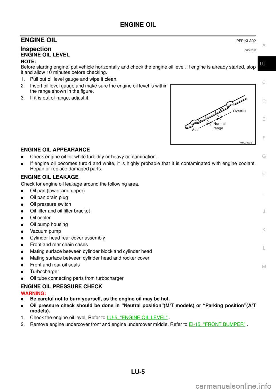
2. Insert oil level gauge and make sure the engine oil level is within
the range shown in the figure.
3. If it is out of range, adjust it.
ENGINE OIL APPEARANCE
lCheck engine oil for white turbidity or heavy contamination.
lIf engine oil becomes turbid and white, it is highly probable that it is contaminated with engine coolant.
Repair or replace damaged parts.
ENGINE OIL LEAKAGE
Check for engine oil leakage around the following area.
lOil pan (lower and upper)
lOil pan drain plug
lOil pressure switch
lOil filter and oil filter bracket
lOil cooler
lOil pump housing
lVa c u u m p u m p
lCylinder head rear cover assembly
lFront and rear chain cases
lMating surface between cylinder block and cylinder head
lMating surface between cylinder head and rocker cover
lFront and rear oil seals
lTurbocharger
lOil tube connecting parts from turbocharger
ENGINE OIL PRESSURE CHECK
WARNING:
lBe careful not to burn yourself, as the engine oil may be hot.
lOil pressure check should be done in “Neutral position”(M/T models) or “Parking position”(A/T
models).
1. Check the engine oil level. Refer toLU-5, "
ENGINE OIL LEVEL".
2. Remove engine undercover front and engine undercover middle. Refer toEI-15, "
FRONT BUMPER".
PBIC2823E