2005 NISSAN NAVARA Panel control AC
[x] Cancel search: Panel control ACPage 496 of 3171

AV-8
SYSTEM DESCRIPTION
Component Description
EKS00Q5Y
AUDIO UNIT
Perform AUDIO operation by AV SWITCH for models with navigation system.
NAVI CONTROL UNIT
lThe gyro (angular speed sensor) and the DVD-ROM drive are
built-in units that control the navigation functions.
lSignals are received from the gyro, the vehicle speed sensor,
and the GPS antenna. Vehicle location is determined by com-
bining this data with the data contained in the DVD-ROM map.
Locational information is shown on liquid crystal display panel.
DVD-ROM Drive
lDVD loading slot (1)
Maps, traffic control regulations, and other pertinent information can
be easily read from the DVD-ROM disc.
Map DVD-ROM
lThe map DVD-ROM has maps, traffic control regulations, and other pertinent information.
lTo improve DVD-ROM map matching and route determination functions, the DVD-ROM uses an exclusive
Nissan format. Therefore, the use of a DVD-ROM provided by other manufacturers cannot be used.
Gyro (Angular Speed Sensor)
lThe oscillator gyro sensor is used to detect changes in vehicle steering angle.
lThe gyro is built into the navigation (NAVI) control unit.
1. 1CD player type 2. 6CD player type 3. 6CD player type (With navigation
system)
SKIB4066E
SKIB4067E
SKIB4068E
Page 497 of 3171

SYSTEM DESCRIPTION
AV-9
C
D
E
F
G
H
I
J
L
MA
B
AV
GPS ANTENNA
lGPS antenna (1)
lDisplay (2)
The GPS antenna receives and amplifies the radio waves from the
GPS satellites, and then transmits the GPS signal to NAVI control
unit.
DISPLAY UNIT
lImages on the display include RGB image such as map screen
and rear-view image displayed when set the select lever to R
range.
lNAVI control unit controls images on the display.
AV S W I T C H
For operation panel, centralized switch integrated with the audio and
NAVI operation has been adopted. The operation signal is sent to
NAVI control unit via communication.
SKIB4501E
SKIB3893E
SKIB4069E
Page 547 of 3171
DIAGNOSIS SYSTEM
AV-59
C
D
E
F
G
H
I
J
L
MA
B
AV
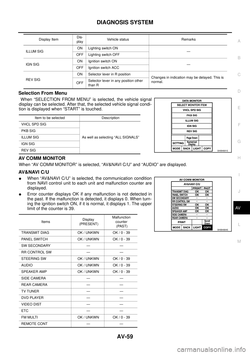
Selection From Menu
When “SELECTION FROM MENU” is selected, the vehicle signal
display can be selected. After that, the selected vehicle signal condi-
tion is displayed when “START” is touched.
AV C O M M M O N I T O R
When “AV COMM MONITOR” is selected, “AV&NAVI C/U” and “AUDIO” are displayed.
AV&NAVI C/U
lWhen “AV&NAVI C/U” is selected, the communication condition
from NAVI control unit to each unit and malfunction counter are
displayed.
lError counter displays OK if any malfunction is not detected in
the past. If the malfunction is detected, it displays 0. When turn-
ing the ignition switch ON, if it is normal, it displays 1. The upper
limitofthecounteris39.
ILLUM SIGON Lighting switch ON
—
OFF Lighting switch OFF
IGN SIGON Ignition switch ON
—
OFF Ignition switch ACC
REV SIGON Selector lever in R position
Changes in indication may be delayed. This is
normal.
OFFSelector lever in any position other
than R Display ItemDis-
playVehicle status Remarks
Item to be selected Description
VHCL SPD SIG
As well as selecting “ALL SIGNALS” PKB SIG
ILLUM SIG
IGN SIG
REV SIG
SKIB4681E
ItemsDisplay
(PRESENT)Malfunction
counter
(PAST)
TRANSMIT DIAG OK / UNKWN OK / 0 - 39
PANEL SWITCH OK / UNKWN OK / 0 - 39
SW SECONDARY — —
RR CONTROL SW — —
STEERING SW OK / UNKWN OK / 0 - 39
AUDIO OK / UNKWN OK / 0 - 39
SPEAKER AMP OK / UNKWN OK / 0 - 39
SIDE CAMERA — —
REAR CAMERA — —
TV TUNER — —
DVD PLAYER — —
VIDEO DIST — —
ETC — —
FM MULTI OK / UNKWN OK / 0 - 39
REMOTE CONT — —
SKIB4684E
Page 583 of 3171
BCM (BODY CONTROL MODULE)
BCS-17
C
D
E
F
G
H
I
J
L
MA
B
BCS
ConfigurationEKS00PA6
Refer toGI-37, "Configuration (BCM)".
Removal and Installation of BCMEKS00PA7
REMOVAL
CAUTION:
If possible, before removing BCM, retrieve current BCM configuration to use for reference when con-
figuring brand-new BCM after installation. Refer toGI-37, "
Configuration (BCM)".
1. Disconnect the battery cable from the negative terminal.
2. Remove lower instrument panel LH. Refer toIP-10, "
Removal and Installation".
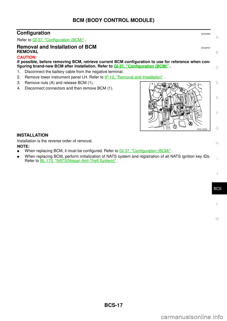
3. Remove nuts (A) and release BCM (1).
4. Disconnect connectors and then remove BCM (1).
INSTALLATION
Installation is the reverse order of removal.
NOTE:
lWhen replacing BCM, it must be configured. Refer toGI-37, "Configuration (BCM)".
lWhen replacing BCM, perform initialization of NATS system and registration of all NATS ignition key IDs.
Refer toBL-170, "
NATS(Nissan Anti-Theft System)".
PKIC1222E
Page 585 of 3171

BL-1
BODY, LOCK & SECURITY SYSTEM
IBODY
CONTENTS
C
D
E
F
G
H
J
K
L
M
SECTIONBL
A
B
BL
BODY, LOCK & SECURITY SYSTEM
PRECAUTIONS .......................................................... 4
Precautions for Supplemental Restraint System
(SRS)“AIRBAG”and“SEATBELTPRE-TEN-
SIONER” .................................................................. 4
Precautions for procedures with out cowl top cover..... 4
Precautions for Work ................................................ 4
Wiring Diagrams and Trouble Diagnosis .................. 4
PREPARATION ........................................................... 5
Commercial Service Tools ........................................ 5
SQUEAK AND RATTLE TROUBLE DIAGNOSES..... 6
Work Flow ................................................................ 6
CUSTOMER INTERVIEW ..................................... 6
DUPLICATE THE NOISE AND TEST DRIVE ....... 7
CHECK RELATED SERVICE BULLETINS ........... 7
LOCATE THE NOISE AND IDENTIFY THE
ROOT CAUSE ...................................................... 7
REPAIR THE CAUSE ........................................... 7
CONFIRM THE REPAIR ....................................... 8
Generic Squeak and Rattle Troubleshooting ........... 8
INSTRUMENT PANEL .......................................... 8
CENTER CONSOLE ............................................. 8
DOORS ................................................................. 8
TRUNK .................................................................. 9
SUNROOF/HEADLINING ..................................... 9
SEATS ................................................................... 9
UNDERHOOD ....................................................... 9
Diagnostic Worksheet ............................................ 10
HOOD ....................................................................... 12
Fitting Adjustment .................................................. 12
LONGITUDINAL AND LATERAL CLEARANCE
ADJUSTMENT .................................................... 13
FRONT END HEIGHT ADJUSTMENT ............... 13
SURFACE HEIGHT ADJUSTMENT ................... 13
Removal and Installation of Hood Assembly .......... 14
REMOVAL ........................................................... 14
INSTALLATION ................................................... 14
Removal and Installation of Hood Hinge ................ 15
REMOVAL ........................................................... 15
INSTALLATION ................................................... 15
Removal and Installation of Hood Lock Control ..... 15REMOVAL ........................................................... 15
INSTALLATION ................................................... 16
Hood Lock Control Inspection ................................ 17
RADIATOR CORE SUPPORT .................................. 18
Removal and Installation ........................................ 18
REMOVAL ........................................................... 18
INSTALLATION ................................................... 19
FRONT FENDER ...................................................... 20
Removal and Installation ........................................ 20
REMOVAL ........................................................... 20
INSTALLATION ................................................... 20
POWER DOOR LOCK SYSTEM .............................. 21
Component Parts and Harness Connector Location... 21
KING CAB ........................................................... 21
DOUBLE CAB ..................................................... 22
System Description ................................................. 23
OUTLINE ............................................................. 24
CAN Communication System Description .............. 25
CAN Communication Unit ....................................... 25
Schematic ............................................................... 26
Wiring Diagram —D/LOCK— ................................. 27
Terminals and Reference Value for BCM ............... 34
CONSULT-II Function (BCM) ................................. 35
CONSULT-II BASIC OPERATION PROCEDURE
... 35
CONSULT-II APPLICATION ITEMS .................... 36
Work Flow ............................................................... 37
Trouble Diagnoses Chart by Symptom ................... 37
Check Power Supply and Ground Circuit ............... 37
Check Door Switch ................................................. 39
CHECK DOOR SWITCH (DOUBLE CAB) .......... 39
CHECK DOOR SWITCH (KING CAB) ................ 41
Check Key Switch ................................................... 43
Check Door Key Cylinder Switch (LHD Model Only)... 45
Check Front Door Lock Actuator (Driver Side) ....... 48
Check Front Door Lock Actuator (Passenger Side)... 49
Check Front Door Lock Actuator Switch ................. 50
Check Rear Door Lock Actuator LH (Double Cab
Model) ..................................................................... 50
Check Rear Door Lock Actuator RH (Double Cab
Page 592 of 3171

BL-8
SQUEAK AND RATTLE TROUBLE DIAGNOSES
FELT CLOTHTAPE
Used to insulate where movement does not occur. Ideal for instrument panel applications.
68370-4B000: 15´25 mm (0.59´0.98 in) pad/68239-13E00: 5 mm (0.20 in) wide tape roll
The following materials, not available through NISSAN Parts Department, can also be used to repair squeaks
and rattles.
UHMW(TEFLON) TAPE
Insulates where slight movement is present. Ideal for instrument panel applications.
SILICONE GREASE
Used in place of UHMW tape that will be visible or not fit.
Note: Will only last a few months.
SILICONE SPRAY
Use when grease cannot be applied.
DUCT TAPE
Use to eliminate movement.
CONFIRM THE REPAIR
Confirm that the cause of a noise is repaired by test driving the vehicle. Operate the vehicle under the same
conditions as when the noise originally occurred. Refer to the notes on the Diagnostic Worksheet.
Generic Squeak and Rattle TroubleshootingEIS00DI3
Refer to Table of Contents for specific component removal and installation information.
INSTRUMENT PANEL
Most incidents are caused by contact and movement between:
1. Cluster lid A and instrument panel
2. Acrylic lens and combination meter housing
3. Instrument panel to front pillar garnish
4. Instrument panel to windshield
5. Instrument panel mounting pins
6. Wiring harnesses behind the combination meter
7. A/C defroster duct and duct joint
These incidents can usually be located by tapping or moving the components to duplicate the noise or by
pressing on the components while driving to stop the noise. Most of these incidents can be repaired by apply-
ing felt cloth tape or silicon spray (in hard to reach areas). Urethane pads can be used to insulate wiring har-
ness.
CAUTION:
Do not use silicone spray to isolate a squeak or rattle. If you saturate the area with silicone, you will
not be able to recheck the repair.
CENTER CONSOLE
Components to pay attention to include:
1. Shifter assembly cover to finisher
2. A/C control unit and cluster lid C
3. Wiring harnesses behind audio and A/C control unit
The instrument panel repair and isolation procedures also apply to the center console.
DOORS
Pay attention to the:
1. Finisher and inner panel making a slapping noise
2. Inside handle escutcheon to door finisher
3. Wiring harnesses tapping
4. Door striker out of alignment causing a popping noise on starts and stops
Tapping or moving the components or pressing on them while driving to duplicate the conditions can isolate
many of these incidents. You can usually insulate the areas with felt cloth tape or insulator foam blocks to
repair the noise.
Page 642 of 3171

BL-58
POWER DOOR LOCK — SUPER LOCK —
When door lock/unlock switch is locked, ground is supplied
lthrough BCM terminal 56
lthrough all door actuators terminal 3
lthrough all door lock actuators terminal 2
lthrough back door lock actuator terminals 1 and 3
lto BCM terminals 54 and 60.
then all doors actuators are locked
Power door unlock operation with door lock/unlock switch
When doors are unlock by door lock/unlock switch, ground is supplied
lto BCM terminal 32
lthrough door lock/unlock switch terminals 2 and 3
lthrough body grounds M21, M80 and M83.
then all doors are locked.
When door lock/unlock switch is unlocked, ground is supplied
lthrough BCM terminals 54 and 60
lthrough all door lock actuators terminal 2
lthrough all door lock actuators terminal 3
lthen all door actuators are unlock
lto BCM terminal 56.
Door lock/unlock switch indicator operation
When door lock/unlock switch is locked, all doors are locked, door lock/unlock switch indicator is on, and
ground is supplied
lto BCM terminal 17
lthrough door lock/unlock switch terminals 5 and 3
lthrough body grounds M21, M80 and M83.
OUTLINE
Power door lock systems with super lock function provides a higher anti-theft performance than conventional
power door lock systems. The super lock system is controlled by BCM (Body Control Module).
Pressing LOCK button on key fob once will lock all doors and activate super lock simultaneously.
When super lock is set, all doors cannot be opened from inside.
Pressing UNLOCK button once on key fob will unlock driver side door (unlock all doors if anti-hijack system is
disabled and during this state, super lock is still active). Second press on the UNLOCK button within 5 second
from the first will unlock all doors and release super lock simultaneously.
Functions Available By Operating the Door Lock/Unlock Switch
lOperating the door lock/unlock switch in the control panel will activate all doors actuator to lock or unlock.
If any doors are opened (except the driver side) during operating the door lock/unlock switch in lock direc-
tion, the door lock actuators will not response. Unlock via the interior door handles and door lock/unlock
switch is always possible.
lOperating the door lock/unlock switch to “LOCK” will lock the vehicle even while driver side door is
opened.
OPERATION
Set Super Lock Conditions
lWhen all these following conditions are met, BCM receives lock signal from key fob.
–All doors are closed.
–Key is out of the ignition key cylinder.
Release Super Lock Conditions
lBCM unit receives a valid unlock signal from key fob.
lIgnition switch is turned ON (door lock/unlock switch will remain its state, super lock is released).
NOTE:
Door lock/unlock switch is incapable of overriding super lock.
Page 673 of 3171
MULTI-REMOTE CONTROL SYSTEM
BL-89
C
D
E
F
G
H
J
K
L
MA
B
BL
MULTI-REMOTE CONTROL SYSTEMPFP:25362
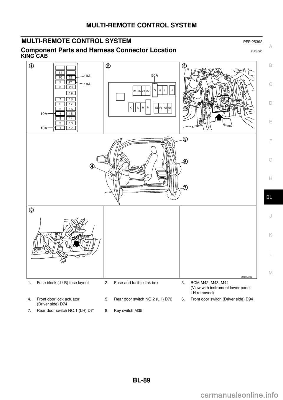
Component Parts and Harness Connector LocationEIS00DBD
KING CAB
1. Fuse block (J / B) fuse layout 2. Fuse and fusible link box 3. BCM M42, M43, M44
(View with instrument lower panel
LH removed)
4. Front door lock actuator
(Driver side) D745. Rear door switch NO.2 (LH) D72 6. Front door switch (Driver side) D94
7. Rear door switch NO.1 (LH) D71 8. Key switch M35
MIIB1030E