2005 NISSAN NAVARA Panel control AC
[x] Cancel search: Panel control ACPage 674 of 3171
BL-90
MULTI-REMOTE CONTROL SYSTEM
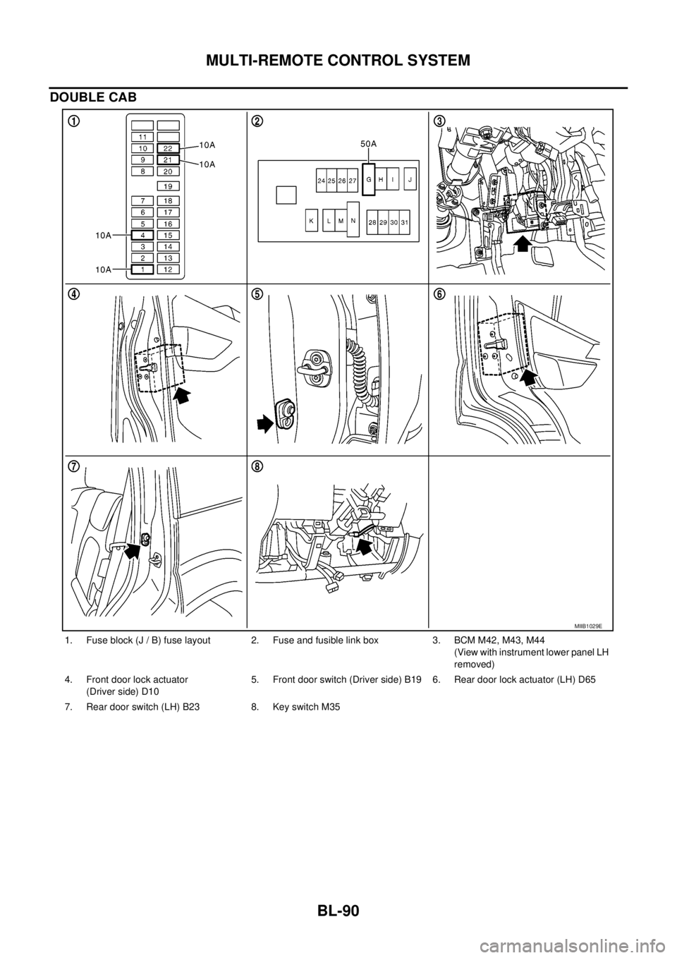
DOUBLE CAB
1. Fuse block (J / B) fuse layout 2. Fuse and fusible link box 3. BCM M42, M43, M44
(View with instrument lower panel LH
removed)
4. Front door lock actuator
(Driver side) D105. Front door switch (Driver side) B19 6. Rear door lock actuator (LH) D65
7. Rear door switch (LH) B23 8. Key switch M35
MIIB1029E
Page 806 of 3171
BR-20
BRAKE BOOSTER
Removal and Installation
EFS005SU
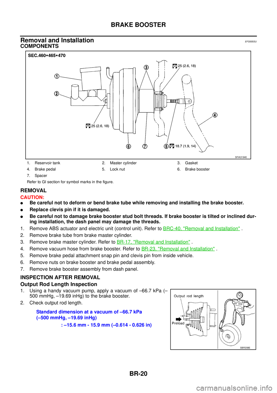
COMPONENTS
REMOVAL
CAUTION:
lBe careful not to deform or bend brake tube while removing and installing the brake booster.
lReplace clevis pin if it is damaged.
lBe careful not to damage brake booster stud bolt threads. If brake booster is tilted or inclined dur-
ing installation, the dash panel may damage the threads.
1. Remove ABS actuator and electric unit (control unit). Refer toBRC-40, "
Removal and Installation".
2. Remove brake tube from brake master cylinder.
3. Remove brake master cylinder. Refer toBR-17, "
Removal and Installation".
4. Remove vacuum hose from brake booster. Refer toBR-23, "
Removal and Installation".
5. Remove brake pedal attachment snap pin and clevis pin from inside vehicle.
6. Remove nuts on brake booster and brake pedal assembly.
7. Remove brake booster assembly from dash panel.
INSPECTION AFTER REMOVAL
Output Rod Length Inspection
1. Using a handy vacuum pump, apply a vacuum of –66.7 kPa (–
500 mmHg, –19.69 inHg) to the brake booster.
2. Check output rod length.
1. Reservoir tank 2. Master cylinder 3. Gasket
4. Brake pedal 5. Lock nut 6. Brake booster
7. Spacer
Refer to GI section for symbol marks in the figure.
SFIA3194E
Standard dimension at a vacuum of –66.7 kPa
(–500 mmHg, –19.69 inHg)
: –15.6 mm - 15.9 mm (–0.614 - 0.626 in)
SBR208E
Page 807 of 3171
BRAKE BOOSTER
BR-21
C
D
E
G
H
I
J
K
L
MA
B
BR
INSTALLATION
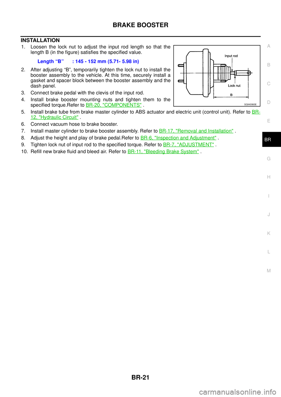
1. Loosen the lock nut to adjust the input rod length so that the
length B (in the figure) satisfies the specified value.
2. After adjusting “B”, temporarily tighten the lock nut to install the
booster assembly to the vehicle. At this time, securely install a
gasket and spacer block between the booster assembly and the
dash panel.
3. Connect brake pedal with the clevis of the input rod.
4. Install brake booster mounting nuts and tighten them to the
specified torque.Refer toBR-20, "
COMPONENTS".
5. Install brake tube from brake master cylinder to ABS actuator and electric unit (control unit). Refer toBR-
12, "Hydraulic Circuit".
6. Connect vacuum hose to brake booster.
7. Install master cylinder to brake booster assembly. Refer toBR-17, "
Removal and Installation".
8. Adjust the height and play of brake pedal.Refer toBR-6, "
Inspection and Adjustment".
9. Tighten lock nut of input rod to the specified torque. Refer toBR-7, "
ADJUSTMENT".
10. Refill new brake fluid and bleed air. Refer toBR-11, "
Bleeding Brake System". Length“B” :145-152mm(5.71-5.98in)
SGIA0060E
Page 821 of 3171

SERVICE DATA AND SPECIFICATIONS (SDS)
BR-35
C
D
E
G
H
I
J
K
L
MA
B
BR
SERVICE DATA AND SPECIFICATIONS (SDS)PFP:00030
General SpecificationsEFS005T8
Unit: mm (in)
Brake PedalEFS005T9
Unit: mm (in)
Brake BoosterEFS005TA
Va c u u m t y p e
Unit: mm (in)
Check ValveEFS005TB
Front Disc BrakeEFS005TC
Unit: mm (in) Front brake Brake model CLZ33VB
Cylinder bore diameter 46.4 (1.83)´2
Pad length´width´thickness 140´47.8´11 ( 5 . 5 1´1.88´0.43)
Rotor outer diameter´thickness 296´28 (11.65´1.10)
Rear brake Brake model LT30
Cylinder bore diameter 38.1 (1.50)
Lining Length´width´thickness 295´55´5.5 (11.61´2.17´0.22)
Drum inner diameter 295 (11.61)
Master cylinder Cylinder bore diameter 25.4 (1.0)
Control valve Valve model Electric brake force distribution
Brake booster Booster model C215T
Diaphragm diameterPrimary 228.5 (9.0)
Secondary 203 (8.0)
Recommended brake fluid DOT 3 or DOT 4
Brake pedal height (From dash lower panel top surface)LHD modelA/T 164.1-174.1 (6.46-6.85)
M/T 171.2-181.2 (6.74-7.13)
RHD modelA/T 174.7-184.7 (6.88-7.27)
M/T 182.1-192.1 (7.17-7.56)
Brake pedal depressed height [Under a force of 490 N (50 kg, 110 lb)
with the engine running]LHD model 120 (4.72) or more
RHD model 110 (4.33) or more
Clearance between bracket and the threaded end of the stop lamp switch 0.74 - 1.96 (0.0291 - 0.0772)
Pedal play3-11(0.12-0.43)
Input rod installation standard dimension 145 - 152 (5.71 - 5.98)
Vacuum leakage
[at vacuum of –66.7 kPa (–500 mmHg, –19.69 inHg)]within 1.3 kPa (10 mmHg, 0.39 inHg) of vacuum for 15 seconds
Brake modelCLZ33VB
Brake padStandard thickness 11.0 (0.43)
Repair limit thickness 2.0 (0.08)
Disc rotorStandard thickness 28.0 (1.102)
Repair limit 26.0 (1.024)
Thickness variation (measured at 8 positions) 0.005 (0.0002)
Runout limit (with it attached to the vehicle) 0.05 (0.002)
Page 1041 of 3171
TROUBLE DIAGNOSIS
EC-61
C
D
E
F
G
H
I
J
K
L
MA
EC
INSPECTION PROCEDURE
CAUTION:
If CONSULT-II is used with no connection of CONSULT-II CONVERTER, malfunctions might be
detected in self-diagnosis depending on control unit which carry out CAN communication.
1. Turn ignition switch OFF.
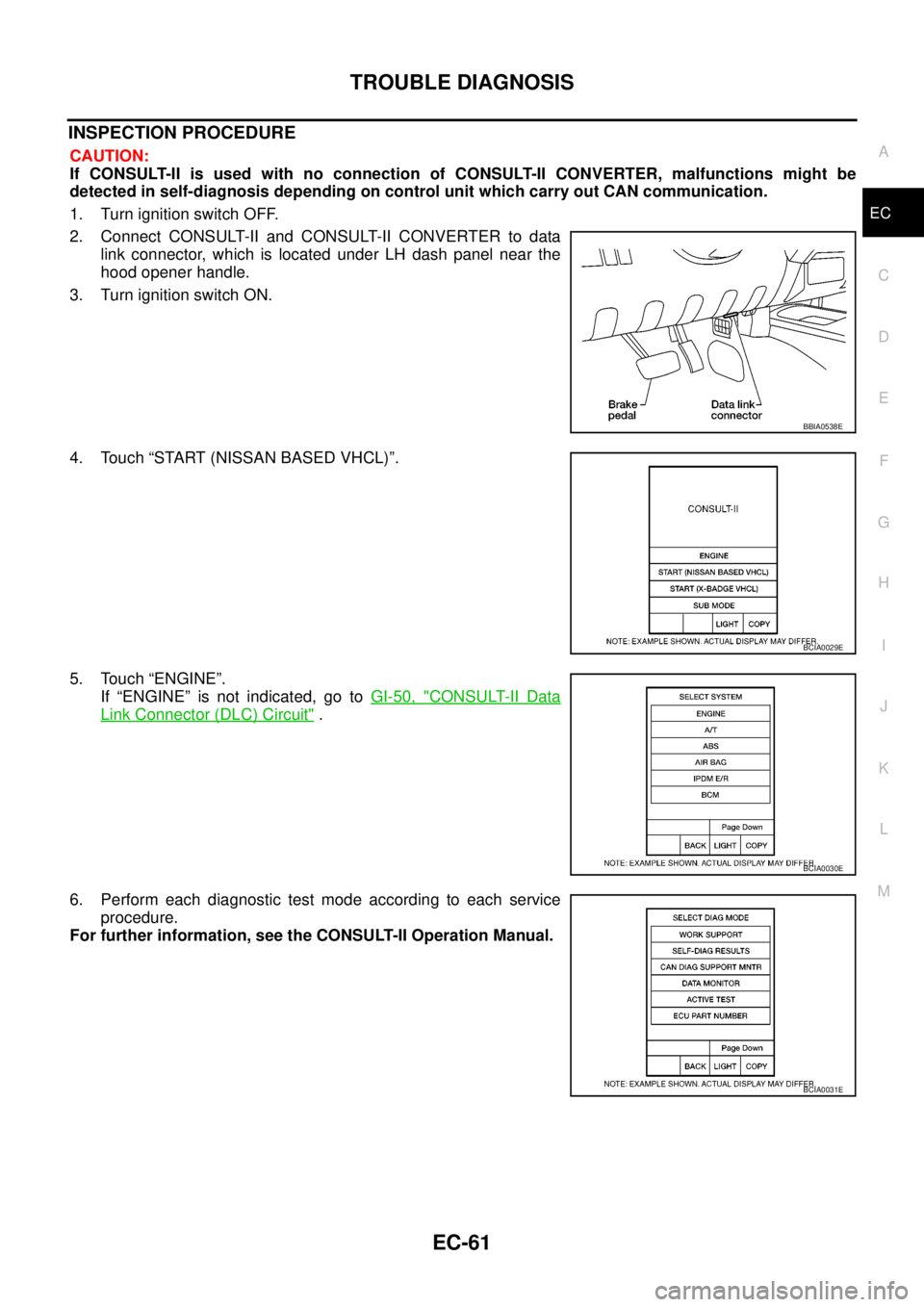
2. Connect CONSULT-II and CONSULT-II CONVERTER to data
link connector, which is located under LH dash panel near the
hood opener handle.
3. Turn ignition switch ON.
4. Touch “START (NISSAN BASED VHCL)”.
5. Touch “ENGINE”.
If “ENGINE” is not indicated, go toGI-50, "
CONSULT-II Data
Link Connector (DLC) Circuit".
6. Perform each diagnostic test mode according to each service
procedure.
For further information, see the CONSULT-II Operation Manual.
BBIA0538E
BCIA0029E
BCIA0030E
BCIA0031E
Page 1346 of 3171

EI-8
SQUEAK AND RATTLE TROUBLE DIAGNOSES
3. Instrument panel to front pillar garnish
4. Instrument panel to windshield
5. Instrument panel mounting pins
6. Wiring harnesses behind the combination meter
7. A/C defroster duct and duct joint
These incidents can usually be located by tapping or moving the components to duplicate the noise or by
pressing on the components while driving to stop the noise. Most of these incidents can be repaired by apply-
ing felt cloth tape or silicone spray (in hard to reach areas). Urethane pads can be used to insulate wiring har-
ness.
CAUTION:
Do not use silicone spray to isolate a squeak or rattle. If you saturate the area with silicone, you will
not be able to recheck the repair.
CENTER CONSOLE
Components to pay attention to include:
1. Shifter assembly cover to finisher
2. A/C control unit and cluster lid C
3. Wiring harnesses behind audio and A/C control unit
The instrument panel repair and isolation procedures also apply to the center console.
DOORS
Pay attention to the:
1. Finisher and inner panel making a slapping noise
2. Inside handle escutcheon to door finisher
3. Wiring harnesses tapping
4. Door striker out of alignment causing a popping noise on starts and stops
Tapping or moving the components or pressing on them while driving to duplicate the conditions can isolate
many of these incidents.
TRUNK
Trunk noises are often caused by a loose jack or loose items put into the trunk by the owner.
In addition look for:
1. Trunk lid bumpers out of adjustment
2. Trunk lid striker out of adjustment
3. The trunk lid torsion bars knocking together
4. A loose license plate or bracket
Most of these incidents can be repaired by adjusting, securing or insulating the item(s) or component(s) caus-
ing the noise.
SUNROOF/HEADLINING
Noises in the sunroof/headlining area can often be traced to one of the following:
1. Sunroof lid, rail, linkage or seals making a rattle or light knocking noise
2. Sun visor shaft shaking in the holder
3. Front or rear windshield touching headliner and squeaking
Again, pressing on the components to stop the noise while duplicating the conditions can isolate most of these
incidents. Repairs usually consist of insulating with felt cloth tape.
OVERHEAD CONSOLE (FRONT AND REAR)
Overhead console noises are often caused by the console panel clips not being engaged correctly. Most of
these incidents are repaired by pushing up on the console at the clip locations until the clips engage.
In addition look for:
1. Loose harness or harness connectors.
2. Front console map/reading lamp lens loose.
3. Loose screws at console attachment points.
Page 1625 of 3171

PRECAUTIONS
GI-3
C
D
E
F
G
H
I
J
K
L
MB
GI
PRECAUTIONSPFP:00001
DescriptionEAS001GG
Observe the following precautions to ensure safe and proper servicing. These precautions are not
described in each individual section.
Precautions for Supplemental Restraint System (SRS) “AIR BAG” and “SEAT
BELT PRE-TENSIONER”
EAS001GH
The Supplemental Restraint System such as “AIR BAG” and “SEAT BELT PRE-TENSIONER”, used along
with a front seat belt, helps to reduce the risk or severity of injury to the driver and front passenger for certain
types of collision. Information necessary to service the system safely is included in the SRS and SB section of
this Service Manual.
WARNING:
lTo avoid rendering the SRS inoperative, which could increase the risk of personal injury or death
in the event of a collision which would result in air bag inflation, all maintenance must be per-
formed by an authorized NISSAN/INFINITI dealer.
lImproper maintenance, including incorrect removal and installation of the SRS, can lead to per-
sonal injury caused by unintentional activation of the system. For removal of Spiral Cable and Air
Bag Module, see the SRS section.
lDo not use electrical test equipment on any circuit related to the SRS unless instructed to in this
Service Manual. SRS wiring harnesses can be identified by yellow and/or orange harnesses or
harness connectors.
Precautions for NATS (NISSAN ANTI-THEFT SYSTEM)EAS001GI
NATS will immobilize the engine if someone tries to start it without the registered key of NATS.
Both of the originally supplied ignition key IDs have been NATS registered.
The security indicator is located on the instrument panel. The indicator blinks when the immobilizer system is
functioning.
Therefore, NATS warns outsiders that the vehicle is equipped with the anti-theft system.
lWhen NATS detects trouble, the security indicator lamp lights up while ignition switch is in "ON" position.
This lighting up indicates that the anti-theft is not functioning, so prompt service is required.
lWhen servicing NATS (trouble diagnoses, system initialization and additional registration of other NATS
ignition key IDs), CONSULT-II hardware and CONSULT-II NATS software is necessary.
Regarding the procedures of NATS initialization and NATS ignition key ID registration, refer to CONSULT-
II operation manual, NATS.
Therefore, CONSULT-II NATS software (program card and operation manual) must be kept strictly con-
fidential to maintain the integrity of the anti-theft function.
lWhen servicing NATS (trouble diagnoses, system initialization and additional registration of other NATS
ignition key IDs), it may be necessary to re-register original key identification. Therefore, be sure to
receive all keys from vehicle owner. A maximum of four or five key IDs can be registered into NATS.
lWhen failing to start the engine first time using the key of NATS, start as follows.
1. Leave the ignition key in "ON" position for approximately 5 seconds.
2. Turn ignition key to "OFF" or "LOCK" position and wait approximately 5 seconds.
3. Repeat step 1 and 2 again.
4. Restart the engine while keeping the key separate from any others on key-chain.
Precautions Necessary for Steering Wheel Rotation After Battery DisconnectEAS001HY
NOTE:
lThis Procedure is applied only to models with Intelligent Key system and NATS (NISSAN ANTI-THEFT
SYSTEM).
lRemove and install all control units after disconnecting both battery cables with the ignition knob in the
²LOCK²position.
lAlways use CONSULT-II to perform self-diagnosis as a part of each function inspection after finishing
work. If DTC is detected, perform trouble diagnosis according to self-diagnostic results.
For models equipped with the Intelligent Key system and NATS, an electrically controlled steering lock mech-
anism is adopted on the key cylinder.
Page 1693 of 3171

SQUEAK AND RATTLE TROUBLE DIAGNOSES
GW-7
C
D
E
F
G
H
J
K
L
MA
B
GW
FELT CLOTHTAPE
Used to insulate where movement does not occur. Ideal for instrument panel applications.
68370-4B000: 15´25 mm (0.59´0.98 in) pad/68239-13E00: 5 mm (0.20 in) wide tape roll
The following materials, not available through NISSAN Parts Department, can also be used to repair squeaks
and rattles.
UHMW(TEFLON) TAPE
Insulates where slight movement is present. Ideal for instrument panel applications.
SILICONE GREASE
Used in place of UHMW tape that will be visible or not fit.
Note: Will only last a few months.
SILICONE SPRAY
Use when grease cannot be applied.
DUCT TAPE
Usetoeliminatemovement.
CONFIRM THE REPAIR
Confirm that the cause of a noise is repaired by test driving the vehicle. Operate the vehicle under the same
conditions as when the noise originally occurred. Refer to the notes on the Diagnostic Worksheet.
Generic Squeak and Rattle TroubleshootingEIS00C03
Refer to Table of Contents for specific component removal and installation information.
INSTRUMENT PANEL
Most incidents are caused by contact and movement between:
1. Cluster lid A and instrument panel
2. Acrylic lens and combination meter housing
3. Instrument panel to front pillar garnish
4. Instrument panel to windshield
5. Instrument panel mounting pins
6. Wiring harnesses behind the combination meter
7. A/C defroster duct and duct joint
These incidents can usually be located by tapping or moving the components to duplicate the noise or by
pressing on the components while driving to stop the noise. Most of these incidents can be repaired by
applying felt cloth tape or silicon spray (in hard to reach areas). Urethane pads can be used to insulate
wiring harness.
CAUTION:
Do not use silicone spray to isolate a squeak or rattle. If you saturate the area with silicone, you
will not be able to recheck the repair.
CENTER CONSOLE
Components to pay attention to include:
1. Shifter assembly cover to finisher
2. A/C control unit and cluster lid C
3. Wiring harnesses behind audio and A/C control unit
The instrument panel repair and isolation procedures also apply to the center console.
DOORS
Pay attention to the:
1. Finisher and inner panel making a slapping noise
2. Inside handle escutcheon to door finisher
3. Wiring harnesses tapping
4. Door striker out of alignment causing a popping noise on starts and stops
Tapping or moving the components or pressing on them while driving to duplicate the conditions can isolate
many of these incidents. You can usually insulate the areas with felt cloth tape or insulator foam blocks to
repair the noise.