Page 1773 of 3171
IP-14
INSTRUMENT PANEL ASSEMBLY
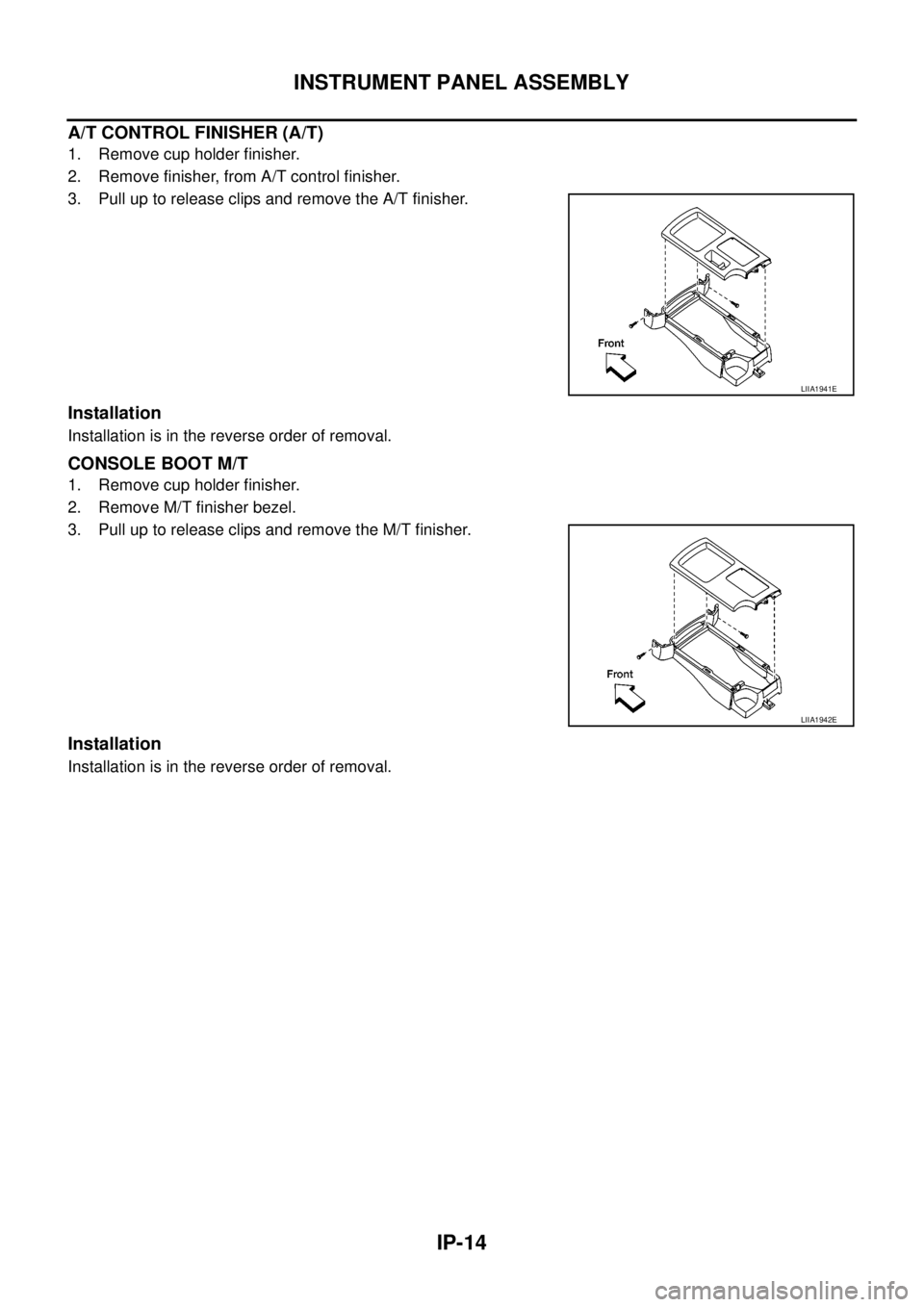
A/T CONTROL FINISHER (A/T)
1. Remove cup holder finisher.
2. Remove finisher, from A/T control finisher.
3. Pull up to release clips and remove the A/T finisher.
Installation
Installation is in the reverse order of removal.
CONSOLE BOOT M/T
1. Remove cup holder finisher.
2. Remove M/T finisher bezel.
3. Pull up to release clips and remove the M/T finisher.
Installation
Installation is in the reverse order of removal.
LIIA1941E
LIIA1942E
Page 1775 of 3171
IP-16
INSTRUMENT PANEL ASSEMBLY
CENTER CONSOLE
Removal
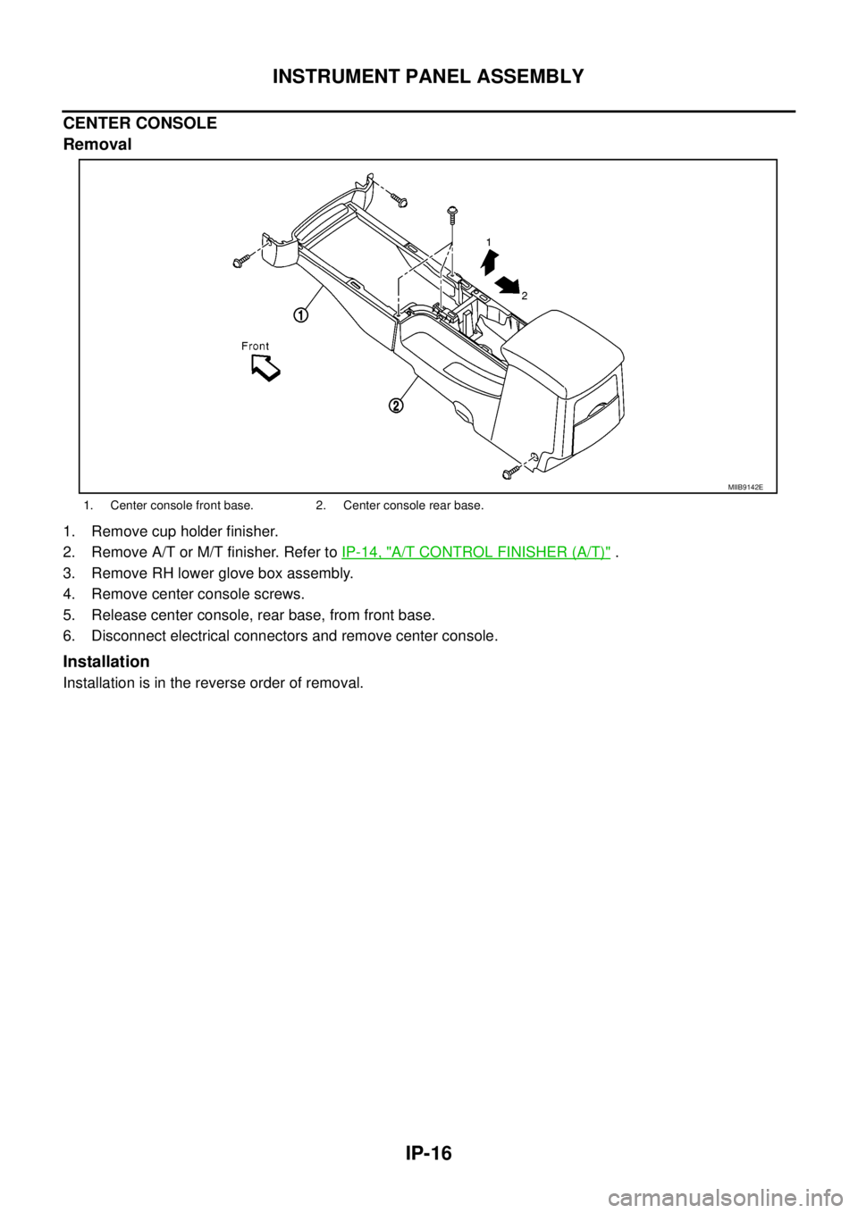
1. Remove cup holder finisher.
2. Remove A/T or M/T finisher. Refer toIP-14, "
A/T CONTROL FINISHER (A/T)".
3. Remove RH lower glove box assembly.
4. Remove center console screws.
5. Release center console, rear base, from front base.
6. Disconnect electrical connectors and remove center console.
Installation
Installation is in the reverse order of removal.
1. Center console front base. 2. Center console rear base.
MIIB9142E
Page 1776 of 3171
INSTRUMENT PANEL ASSEMBLY
IP-17
C
D
E
F
G
H
J
K
L
MA
B
IP
Disassembly and AssemblyEIS00DZ0
CENTER CONSOLE
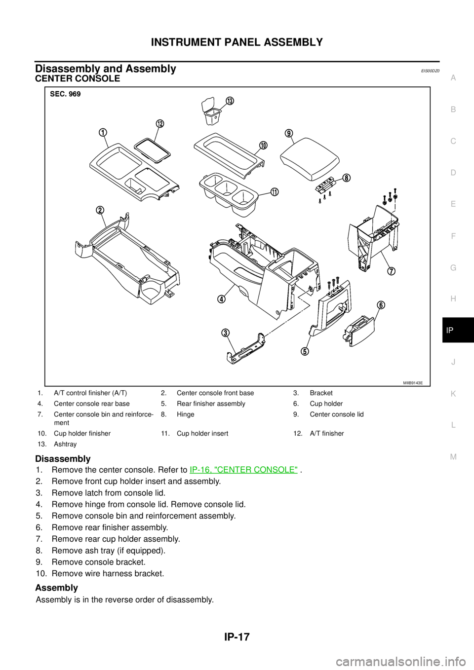
Disassembly
1. Remove the center console. Refer toIP-16, "CENTER CONSOLE".
2. Remove front cup holder insert and assembly.
3. Remove latch from console lid.
4. Remove hinge from console lid. Remove console lid.
5. Remove console bin and reinforcement assembly.
6. Remove rear finisher assembly.
7. Remove rear cup holder assembly.
8. Remove ash tray (if equipped).
9. Remove console bracket.
10. Remove wire harness bracket.
Assembly
Assembly is in the reverse order of disassembly.
MIIB9143E
1. A/T control finisher (A/T) 2. Center console front base 3. Bracket
4. Center console rear base 5. Rear finisher assembly 6. Cup holder
7. Center console bin and reinforce-
ment8. Hinge 9. Center console lid
10. Cup holder finisher 11. Cup holder insert 12. A/T finisher
13. Ashtray
Page 2153 of 3171
LT-70
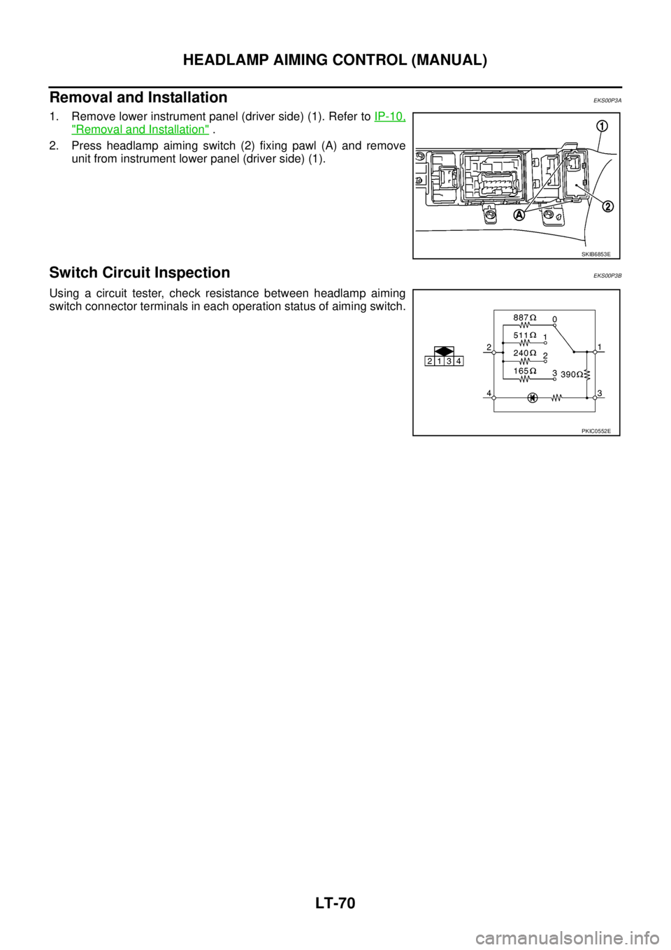
HEADLAMP AIMING CONTROL (MANUAL)
Removal and Installation
EKS00P3A
1. Remove lower instrument panel (driver side) (1). Refer toIP-10,
"Removal and Installation".
2. Press headlamp aiming switch (2) fixing pawl (A) and remove
unit from instrument lower panel (driver side) (1).
Switch Circuit InspectionEKS00P3B
Using a circuit tester, check resistance between headlamp aiming
switch connector terminals in each operation status of aiming switch.
SKIB6853E
PKIC0552E
Page 2488 of 3171
AIR CONDITIONER FILTER
MTC-101
C
D
E
F
G
H
I
K
L
MA
B
MTC
AIR CONDITIONER FILTERPFP:27277
Removal and InstallationEJS005GW
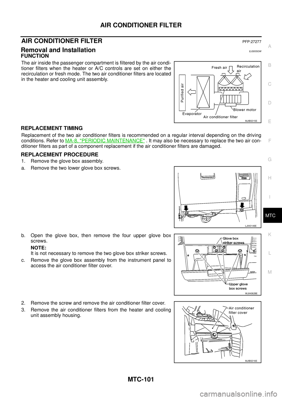
FUNCTION
The air inside the passenger compartment is filtered by the air condi-
tioner filters when the heater or A/C controls are set on either the
recirculation or fresh mode. The two air conditioner filters are located
in the heater and cooling unit assembly.
REPLACEMENT TIMING
Replacement of the two air conditioner filters is recommended on a regular interval depending on the driving
conditions. Refer toMA-8, "
PERIODIC MAINTENANCE". It may also be necessary to replace the two air con-
ditioner filters as part of a component replacement if the air conditioner filters are damaged.
REPLACEMENT PROCEDURE
1. Remove the glove box assembly.
a. Remove the two lower glove box screws.
b. Open the glove box, then remove the four upper glove box
screws.
NOTE:
It is not necessary to remove the two glove box striker screws.
c. Remove the glove box assembly from the instrument panel to
access the air conditioner filter cover.
2. Remove the screw and remove the air conditioner filter cover.
3. Remove the air conditioner filters from the heater and cooling
unit assembly housing.
MJIB0215E
LJIA0146E
WJIA0628E
MJIB0216E
Page 2683 of 3171

RF-6
SQUEAK AND RATTLE TROUBLE DIAGNOSES
FELT CLOTHTAPE
Used to insulate where movement does not occur. Ideal for instrument panel applications.
68370-4B000: 15´25 mm (0.59´0.98 in) pad/68239-13E00: 5 mm (0.20 in) wide tape roll
The following materials, not available through NISSAN Parts Department, can also be used to repair squeaks
and rattles.
UHMW(TEFLON) TAPE
Insulates where slight movement is present. Ideal for instrument panel applications.
SILICONE GREASE
Used in place of UHMW tape that will be visible or not fit.
Note: Will only last a few months.
SILICONE SPRAY
Use when grease cannot be applied.
DUCT TAPE
Use to eliminate movement.
CONFIRM THE REPAIR
Confirm that the cause of a noise is repaired by test driving the vehicle. Operate the vehicle under the same
conditions as when the noise originally occurred. Refer to the notes on the Diagnostic Worksheet.
Generic Squeak and Rattle TroubleshootingEIS00CDZ
Refer to Table of Contents for specific component removal and installation information.
INSTRUMENT PANEL
Most incidents are caused by contact and movement between:
1. Cluster lid A and instrument panel
2. Acrylic lens and combination meter housing
3. Instrument panel to front pillar garnish
4. Instrument panel to windshield
5. Instrument panel mounting pins
6. Wiring harnesses behind the combination meter
7. A/C defroster duct and duct joint
These incidents can usually be located by tapping or moving the components to duplicate the noise or by
pressing on the components while driving to stop the noise. Most of these incidents can be repaired by apply-
ing felt cloth tape or silicon spray (in hard to reach areas). Urethane pads can be used to insulate wiring har-
ness.
CAUTION:
Do not use silicone spray to isolate a squeak or rattle. If you saturate the area with silicone, you will
not be able to recheck the repair.
CENTER CONSOLE
Components to pay attention to include:
1. Shifter assembly cover to finisher
2. A/C control unit and cluster lid C
3. Wiring harnesses behind audio and A/C control unit
The instrument panel repair and isolation procedures also apply to the center console.
DOORS
Pay attention to the:
1. Finisher and inner panel making a slapping noise
2. Inside handle escutcheon to door finisher
3. Wiring harnesses tapping
4. Door striker out of alignment causing a popping noise on starts and stops
Tapping or moving the components or pressing on them while driving to duplicate the conditions can isolate
many of these incidents. You can usually insulate the areas with felt cloth tape or insulator foam blocks to
repair the noise.
Page 2779 of 3171
RFD-76
[WITH ELECTRONIC LOCKING DIFFERENTIAL]
DIFFERENTIAL LOCK CONTROL UNIT
DIFFERENTIAL LOCK CONTROL UNIT
PFP:28496
Removal and InstallationEDS003BC
REMOVAL
1. Turn the ignition switch OFF and disconnect the battery cables.
2. Remove the lower instrument panel LH (LHD models) or lower instrument panel RH (RHD models). Refer
toIP-13, "
LOWER INSTRUMENT PANEL LH"(LHD models) orIP-13, "LOWER INSTRUMENT PANEL
LH"(RHD models).
3. Disconnect the differential lock control unit connector.
4. Remove the two bolts and remove the differential lock control
unit.
INSTALLATION
Installation is in the reverse order of removal.
lWhen installing differential lock control unit, tighten bolts to the specified torque.
lAfter the installation, check DIFF LOCK indicator lamp. Refer toRFD-33, "Precautions for Differential
Case Assembly and Differential Lock Control Unit Replacement".
WDIA0254E
Differential lock control unit bolts : 5.1 N·m (0.52 kg-m, 45 in-lb)
Page 2877 of 3171

SE-6
SQUEAK AND RATTLE TROUBLE DIAGNOSES
FELT CLOTHTAPE
Used to insulate where movement does not occur. Ideal for instrument panel applications.
68370-4B000: 15´25 mm (0.59´0.98 in) pad/68239-13E00: 5 mm (0.20 in) wide tape roll
The following materials, not available through NISSAN Parts Department, can also be used to repair squeaks
and rattles.
UHMW(TEFLON) TAPE
Insulates where slight movement is present. Ideal for instrument panel applications.
SILICONE GREASE
Used in place of UHMW tape that will be visible or not fit.
Note: Will only last a few months.
SILICONE SPRAY
Use when grease cannot be applied.
DUCT TAPE
Use to eliminate movement.
CONFIRM THE REPAIR
Confirm that the cause of a noise is repaired by test driving the vehicle. Operate the vehicle under the same
conditions as when the noise originally occurred. Refer to the notes on the Diagnostic Worksheet.
Generic Squeak and Rattle TroubleshootingEIS00CEI
Refer to Table of Contents for specific component removal and installation information.
INSTRUMENT PANEL
Most incidents are caused by contact and movement between:
1. Cluster lid A and instrument panel
2. Acrylic lens and combination meter housing
3. Instrument panel to front pillar garnish
4. Instrument panel to windshield
5. Instrument panel mounting pins
6. Wiring harnesses behind the combination meter
7. A/C defroster duct and duct joint
These incidents can usually be located by tapping or moving the components to duplicate the noise or by
pressing on the components while driving to stop the noise. Most of these incidents can be repaired by apply-
ing felt cloth tape or silicon spray (in hard to reach areas). Urethane pads can be used to insulate wiring har-
ness.
CAUTION:
Do not use silicone spray to isolate a squeak or rattle. If you saturate the area with silicone, you will
not be able to recheck the repair.
CENTER CONSOLE
Components to pay attention to include:
1. Shifter assembly cover to finisher
2. A/C control unit and cluster lid C
3. Wiring harnesses behind audio and A/C control unit
The instrument panel repair and isolation procedures also apply to the center console.
DOORS
Pay attention to the:
1. Finisher and inner panel making a slapping noise
2. Inside handle escutcheon to door finisher
3. Wiring harnesses tapping
4. Door striker out of alignment causing a popping noise on starts and stops
Tapping or moving the components or pressing on them while driving to duplicate the conditions can isolate
many of these incidents. You can usually insulate the areas with felt cloth tape or insulator foam blocks to
repair the noise.
![NISSAN NAVARA 2005 Repair Workshop Manual RFD-76
[WITH ELECTRONIC LOCKING DIFFERENTIAL]
DIFFERENTIAL LOCK CONTROL UNIT
DIFFERENTIAL LOCK CONTROL UNIT
PFP:28496
Removal and InstallationEDS003BC
REMOVAL
1. Turn the ignition switch OFF and disco](/manual-img/5/57362/w960_57362-2778.png "NISSAN NAVARA 2005 Repair Workshop Manual RFD-76
[WITH ELECTRONIC LOCKING DIFFERENTIAL]
DIFFERENTIAL LOCK CONTROL UNIT
DIFFERENTIAL LOCK CONTROL UNIT
PFP:28496
Removal and InstallationEDS003BC
REMOVAL
1. Turn the ignition switch OFF and disco")