2005 NISSAN NAVARA Panel control AC
[x] Cancel search: Panel control ACPage 1734 of 3171
GW-48
REAR WINDOW DEFOGGER
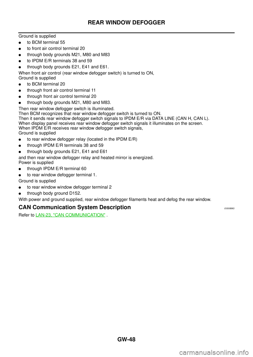
Ground is supplied
lto BCM terminal 55
lto front air control terminal 20
lthrough body grounds M21, M80 and M83
lto IPDM E/R terminals 38 and 59
lthrough body grounds E21, E41 and E61.
When front air control (rear window defogger switch) is turned to ON,
Ground is supplied
lto BCM terminal 20
lthrough front air control terminal 11
lthrough front air control terminal 20
lthrough body grounds M21, M80 and M83.
Then rear window defogger switch is illuminated.
Then BCM recognizes that rear window defogger switch is turned to ON.
Then it sends rear window defogger switch signals to IPDM E/R via DATA LINE (CAN H, CAN L).
When display panel receives rear window defogger switch signals it illuminates on the screen.
When IPDM E/R receives rear window defogger switch signals,
Ground is supplied
lto rear window defogger relay (located in the IPDM E/R)
lthrough IPDM E/R terminals 38 and 59
lthrough body grounds E21, E41 and E61
and then rear window defogger relay and heated mirror is energized.
Power is supplied
lthrough IPDM E/R terminal 60
lto rear window defogger terminal 1.
Ground is supplied
lto rear window window defogger terminal 2
lthrough body ground D152.
With power and ground supplied, rear window defogger filaments heat and defog the rear window.
CAN Communication System DescriptionEIS00B8G
Refer toLAN-23, "CAN COMMUNICATION".
Page 1746 of 3171
GW-60
REAR WINDOW DEFOGGER
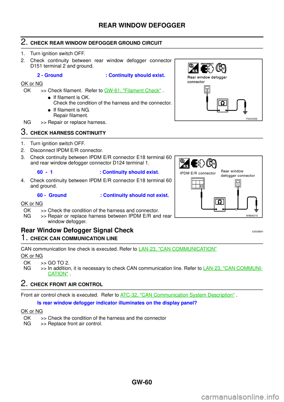
2.CHECK REAR WINDOW DEFOGGER GROUND CIRCUIT
1. Turn ignition switch OFF.
2. Check continuity between rear window defogger connector
D151 terminal 2 and ground.
OK or NG
OK >> Check filament. Refer toGW-61, "Filament Check".
lIf filament is OK.
Check the condition of the harness and the connector.
lIf filament is NG.
Repair filament.
NG >> Repair or replace harness.
3.CHECK HARNESS CONTINUITY
1. Turn ignition switch OFF.
2. Disconnect IPDM E/R connector.
3. Check continuity between IPDM E/R connector E18 terminal 60
and rear window defogger connector D124 terminal 1.
4. Check continuity between IPDM E/R connector E18 terminal 60
and ground.
OK or NG
OK >> Check the condition of the harness and connector.
NG >> Repair or replace harness between IPDM E/R and rear
window defogger.
Rear Window Defogger Signal CheckEIS00B8V
1.CHECK CAN COMMUNICATION LINE
CAN communication line check is executed. Refer toLAN-23, "
CAN COMMUNICATION"
OK or NG
OK >> GO TO 2.
NG >> In addition, it is necessary to check CAN communication line. Refer toLAN-23, "
CAN COMMUNI-
CATION".
2.CHECK FRONT AIR CONTROL
Front air control check is executed. Refer toAT C - 3 2 , "
CAN Communication System Description".
OK or NG
OK >> Check the condition of the harness and the connector
NG >> Replace front air control.2 - Ground : Continuity should exist.
PIIA4235E
60 - 1 : Continuity should exist.
60 - Ground : Continuity should not exist.
MIIB0621E
Is rear window defogger indicator illuminates on the display panel?
Page 1755 of 3171
IDX-3
A
C
D
E
F
G
H
I
J
K
L B
IDX
ALPHABETICAL INDEX
C
Camshaft ...........................................................EM-59
Camshaft inspection ..........................................EM-60
Camshaft position sensor (CMPS) .....EC-82,EC-171,
EC-177
CAN ....................................................................DI-65
CAN - Wiring diagram ...........EC-80,LAN-26,LAN-44,
LAN-56
,LAN-68,LAN-82,LAN-96,LAN-112,LAN-125,
LAN-139
,LAN-152,LAN-166,LAN-181,LAN-198,
LAN-213
,LAN-230,LAN-248,LAN-267,LAN-279
CAN (Controller Area Network) ..BL-25,BL-59,RF-13
CAN communication .....EC-22,EC-79,AT-91,TF-19,
TF-82
,RFD-43,RFD-69,BRC-28,BL-25,BL-59,RF-13,
LT-88
CHARGE - Wiring diagram ................................SC-15
Charging system ................................................SC-14
Chassis and body maintenance ........................MA-28
CHIME - Wiring diagram .....................................DI-53
CIGAR - Wiring diagram ..................................WW-55
Cigarette lighter ...............................................WW-55
Circuit breaker ...................................................PG-74
CKPS - Wiring diagram .....................EC-161,EC-167
Clutch cover .......................................................CL-17
Clutch disc .........................................................CL-17
Clutch master cylinder .........................................CL-9
Clutch operating cylinder ...................................CL-11
Clutch pedal .........................................................CL-6
CMPS - Wiring diagram .....................EC-173,EC-179
Coil spring (front) .............................................FSU-10
Collision diagnosis ...........................................SRS-56
Combination lamp, front, removal and installation ........
LT-30
Combination lamp, rear, removal and installation ........
LT-144
Combination meter ...............................................DI-4
Combination switch ..........................................LT-114
COMBSW - Wiring diagram ..............................LT-114
COMPAS - Wiring diagram .................................DI-68
Compass ............................................................DI-66
Component Location (auto A/C) .......ATC-36,MTC-36
Compression pressure ......................................EM-92
Compressor clutch removal and installation .ATC-143,
MTC-123
Compressor mounting ..................ATC-142,MTC-122
Compressor special service tool .......ATC-16,MTC-16
Condenser ....................................ATC-147,MTC-127
Connecting rod ................................................EM-127
Connecting rod bearing clearance ...................EM-131
Connecting rod bushing clearance ..................EM-127
Console box - See Instrument panel ...................IP-10
CONSULT for all-mode 4WD .............................TF-44
CONSULT-II for engine .....................................EC-59
Control units (terminal arrangement) .................PG-78
Control valve (A/T) .............................................AT-33
Controller Area Network (CAN) ..BL-25,BL-59,RF-13
Converter housing installation .........................AT-250
COOL/F - Wiring diagram ................................EC-135
Cooling circuit (engine) ........................................CO-6
Cooling fan ........................................................CO-19
Cooling fan motor ............................................EC-141
Cooling unit (A/C evaporator) ......ATC-124,ATC-149,
MTC-103
,MTC-129
Counter gear (M/T) ............................................MT-21
Coupling sleeve (M/T) ........................................MT-21
Crankcase ventilation system ............................EC-21
Crankshaft position sensor (TDC) ......EC-82,EC-159,
EC-165
Cylinder block .................................................EM-110
Cylinder block boring ......................................EM-129
Cylinder head ....................................................EM-92
Cylinder head bolt tightening ............................EM-96
Cylinder head gasket selection .........................EM-96
D
Data link connector for Consult ..........................EC-59
Daytime light system ...........................................LT-31
Daytime running light - See Daytime light systemLT-31
Diagnosis sensor unit .....................................SRS-48
Diagnostic trouble code (DTC) ..........................EC-27
Diagnostic trouble code (DTC) for OBD system ..EC-6
Diagnostic trouble code (DTC) inspection priority chart
EC-37
Differential gear oil replacement ...........MA-33,MA-34
DIFLOC - Wiring diagram ...............................RFD-46
Dimensions .........................................................GI-60
Direct clutch solenoid valve ...............AT-142,AT-144
Display and amp.assembly ...............ATC-60,MTC-55
Dome light - See Interior lamp ..........................LT-145
Door glass ...........................................GW-35,GW-38
Door lock ..........................................................BL-126
Door mirror lamp ...............................................LT-145
Door trim .............................................................EI-30
Door, front .............................BL-118,BL-120,GW-35
Door, rear ............................................BL-118,GW-38
Drive belt ...........................................................EM-12
Drive chain (Transfer) .........................TF-114,TF-120
Driver air bag ..................................................SRS-36
DTRL - Wiring diagram .......................................LT-35
Duct and grilles .............................ATC-134,MTC-113
E
ECM input/output signal .....................................EC-52
ECM power supply .............................................EC-71
ECM relay ........................................................EC-232
ECTS - Wiring diagram ....................................EC-105
EGR function ...................................................EC-302
EGR volume control valve ...............................EC-302
EGRC/V - Wiring diagram ................................EC-304
Electric sunroof ..................................................RF-10
Electrical units location ......................................PG-71
Electronic fuel injection pump ...........................EM-49
Engine control circuit diagram ...........................EC-50
Engine control component parts location ...........EC-46
Engine control module (ECM) ...........EC-213,EC-215,
EC-269
Page 1757 of 3171
IDX-5
A
C
D
E
F
G
H
I
J
K
L B
IDX
ALPHABETICAL INDEX
HSEAT - Wiring diagram .......................SE-14,SE-17
I
IATS - Wiring diagram .....................................EC-100
Identification plate ...............................................GI-57
Idle speed ..........................................................EC-38
Ignition key hole illumination .............................LT-145
ILL - Wiring diagram .........................................LT-166
Illumination .......................................................LT-162
In vehicle sensor ...........................ATC-108,ATC-118
INJE/PW - Wiring diagram ...............................EC-284
INJECT - Wiring diagram .....EC-128,EC-240,EC-289
Injection nozzle .......EM-44,EC-123,EC-125,EC-237
Injector adjustment value ...................EC-271,EC-273
Injector adjustment value registration ................EC-25
Input clutch solenoid valve .................AT-132,AT-134
Instrument panel ..................................................IP-10
INT/V - Wiring diagram ....................................EC-315
Intake air control valve control solenoid valve .EC-314
Intake air temperature sensor ............................EC-98
Intake door control linkage adjustment ............ATC-79
Intake door motor ..........ATC-77,ATC-129,MTC-109
Intake manifold ..................................................EM-20
Intake sensor ..ATC-114,ATC-120,MTC-95,MTC-99
Interior .................................................................EI-33
Interior lamp ......................................................LT-145
Interior lamp on-off control ................................LT-145
IPDM (Intelligent power distribution module engine
room) .................................................................PG-14
ISO 15031-2 Terminology ..................................GI-61
J
Jacking points .....................................................GI-52
K
Key illumination ................................................LT-145
KEYLES - Wiring diagram ..................................BL-93
L
Leaf spring (rear) ..............................................RSU-7
Length (Dimensions) ..........................................GI-60
License lamp ....................................................LT-125
Lifting points .......................................................GI-52
Line pressure solenoid valve ...........................AT-114
Line pressure test (A/T) .....................................AT-44
Liquid gasket application ................EM-5,LU-2,CO-2
Location of electrical units .................................PG-71
Low coast brake solenoid valve ..........AT-152,AT-154
Lubricant (R134a) A/C ......................ATC-24,MTC-24
Lubricants ..........................................................MA-14
Lubrication circuit (engine) ..................................LU-4
Lubrication oil A/C ............................ATC-24,MTC-24
Lubrication-locks, hinges and hood latches .......MA-39
M
MAFS - Wiring diagram .....................................EC-94
Magnet clutch .ATC-87,ATC-143,MTC-79,MTC-123
MAIN - Wiring diagram ......................................EC-72
Main drive gear (M/T) ........................................MT-21
Mainshaft (M/T) ..................................................MT-21
Major overhaul (Final drive)FFD-17,RFD-15,RFD-82
Major overhaul (Transfer) ................................TF-112
Malfunction indicator (MI) ..................................EC-28
Map lamp ..........................................................LT-145
Mass air flow sensor (MAFS) .............................EC-92
Master cylinder (brake) ......................................BR-17
Master cylinder (clutch) ........................................CL-9
Meter .....................................................................DI-4
METER - Wiring diagram ....................................DI-10
MI & data link connectors circuit ......................EC-354
MIL/DL - Wiring diagram ..................................EC-354
Mode door control linkage adjustment ............ATC-65,
MTC-59
Mode door motor ............ATC-63,ATC-130,MTC-58,
MTC-110
Model variation ...................................................GI-56
Multiport fuel injection precautions .......................GI-6
N
NATS - Wiring diagram ....................................BL-173
NATS (Nissan anti-theft system) precautions .......GI-3
NVH troubleshooting (AX) .................................FAX-4
NVH troubleshooting (BR) ...................................BR-5
NVH troubleshooting (EM) ................................EM-10
NVH troubleshooting (Final drive) ........FFD-6,RFD-7,
RFD-39
NVH troubleshooting (M/T) ..................................MT-6
NVH troubleshooting (Propeller shaft) .................PR-2
NVH troubleshooting (ST) ....................................PS-5
NVH troubleshooting (Transfer) .........................TF-11
NVH troubleshooting (WT)NVH troubleshooting (WT) .
WT-2
O
Oil cooler (engine) .............................................LU-11
Oil filter .................................................................LU-8
Oil pan (engine) ................................................EM-36
Oil pressure (engine) ...........................................LU-5
Oil pump (A/T) .................................................AT-281
Oil pump (engine) ..............................................LU-14
Oil seal replacement (engine) ...........................EM-70
Oil seal replacement (front of final drive) ...........FFD-9
Oil seal replacement (side of final drive) ..........FFD-13
On board diagnostic system ..............................EC-27
Operating cylinder (clutch) .................................CL-11
Overheat ..........................................................EC-132
Oversize piston ...............................................EM-129
Page 1760 of 3171
IP-1
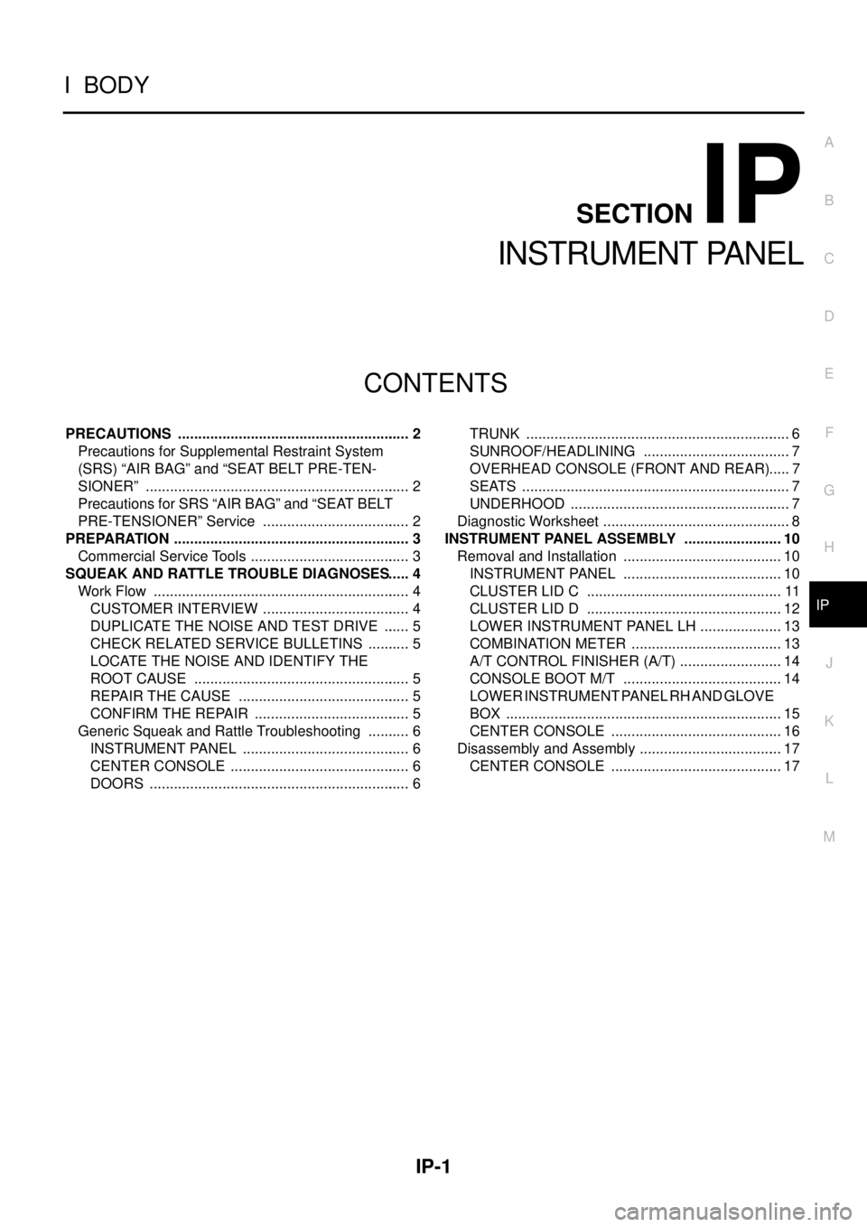
INSTRUMENT PANEL
IBODY
CONTENTS
C
D
E
F
G
H
J
K
L
M
SECTIONIP
A
B
IP
INSTRUMENT PANEL
PRECAUTIONS .......................................................... 2
Precautions for Supplemental Restraint System
(SRS)“AIRBAG”and“SEATBELTPRE-TEN-
SIONER” .................................................................. 2
Precautions for SRS “AIR BAG” and “SEAT BELT
PRE-TENSIONER” Service ..................................... 2
PREPARATION ........................................................... 3
Commercial Service Tools ........................................ 3
SQUEAK AND RATTLE TROUBLE DIAGNOSES..... 4
Work Flow ................................................................ 4
CUSTOMER INTERVIEW ..................................... 4
DUPLICATE THE NOISE AND TEST DRIVE ....... 5
CHECK RELATED SERVICE BULLETINS ........... 5
LOCATE THE NOISE AND IDENTIFY THE
ROOT CAUSE ...................................................... 5
REPAIR THE CAUSE ........................................... 5
CONFIRM THE REPAIR ....................................... 5
Generic Squeak and Rattle Troubleshooting ........... 6
INSTRUMENT PANEL .......................................... 6
CENTER CONSOLE ............................................. 6
DOORS ................................................................. 6TRUNK .................................................................. 6
SUNROOF/HEADLINING ..................................... 7
OVERHEAD CONSOLE (FRONT AND REAR)..... 7
SEATS ................................................................... 7
UNDERHOOD ....................................................... 7
Diagnostic Worksheet ............................................... 8
INSTRUMENT PANEL ASSEMBLY ......................... 10
Removal and Installation ........................................ 10
INSTRUMENT PANEL ........................................ 10
CLUSTER LID C ................................................. 11
CLUSTER LID D ................................................. 12
LOWER INSTRUMENT PANEL LH ..................... 13
COMBINATION METER ...................................... 13
A/T CONTROL FINISHER (A/T) .......................... 14
CONSOLE BOOT M/T ........................................ 14
LOWER INSTRUMENT PANEL RH AND GLOVE
BOX ..................................................................... 15
CENTER CONSOLE ........................................... 16
Disassembly and Assembly .................................... 17
CENTER CONSOLE ........................................... 17
Page 1765 of 3171

IP-6
SQUEAK AND RATTLE TROUBLE DIAGNOSES
Generic Squeak and Rattle Troubleshooting
EIS00DYX
Refer to Table of Contents for specific component removal and installation information.
INSTRUMENT PANEL
Most incidents are caused by contact and movement between:
1. The cluster lid A and instrument panel
2. Acrylic lens and combination meter housing
3. Instrument panel to front pillar garnish
4. Instrument panel to windshield
5. Instrument panel mounting pins
6. Wiring harnesses behind the combination meter
7. A/C defroster duct and duct joint
These incidents can usually be located by tapping or moving the components to duplicate the noise or by
pressing on the components while driving to stop the noise. Most of these incidents can be repaired by apply-
ing felt cloth tape or silicone spray (in hard to reach areas). Urethane pads can be used to insulate wiring har-
ness.
CAUTION:
Do not use silicone spray to isolate a squeak or rattle. If you saturate the area with silicone, you will
not be able to recheck the repair.
CENTER CONSOLE
Components to pay attention to include:
1. Shifter assembly cover to finisher
2. A/C control unit and cluster lid C
3. Wiring harnesses behind audio and A/C control unit
The instrument panel repair and isolation procedures also apply to the center console.
DOORS
Pay attention to the:
1. Finisher and inner panel making a slapping noise
2. Inside handle escutcheon to door finisher
3. Wiring harnesses tapping
4. Door striker out of alignment causing a popping noise on starts and stops
Tapping or moving the components or pressing on them while driving to duplicate the conditions can isolate
many of these incidents. You can usually insulate the areas with felt cloth tape or insulator foam blocks to
repair the noise.
TRUNK
Trunk noises are often caused by a loose jack or loose items put into the trunk by the owner.
In addition look for:
1. Trunk lid bumpers out of adjustment
2. Trunk lid striker out of adjustment
3. The trunk lid torsion bars knocking together
4. A loose license plate or bracket
Most of these incidents can be repaired by adjusting, securing or insulating the item(s) or component(s) caus-
ing the noise.
Page 1769 of 3171
IP-10
INSTRUMENT PANEL ASSEMBLY
INSTRUMENT PANEL ASSEMBLY
PFP:68200
Removal and InstallationEIS00DYZ
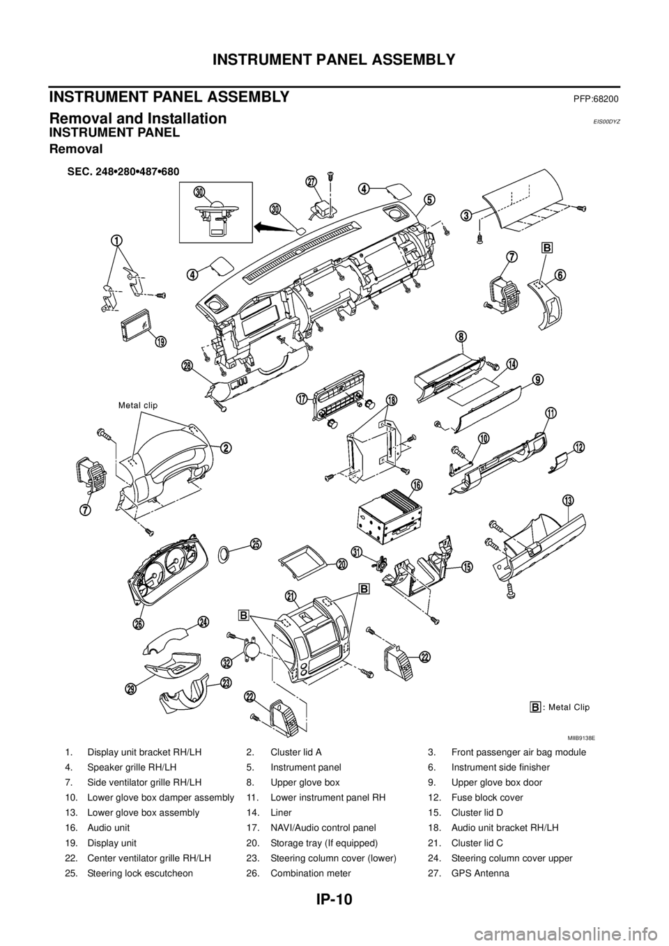
INSTRUMENT PANEL
Removal
1. Display unit bracket RH/LH 2. Cluster lid A 3. Front passenger air bag module
4. Speaker grille RH/LH 5. Instrument panel 6. Instrument side finisher
7. Side ventilator grille RH/LH 8. Upper glove box 9. Upper glove box door
10. Lower glove box damper assembly 11. Lower instrument panel RH 12. Fuse block cover
13. Lower glove box assembly 14. Liner 15. Cluster lid D
16. Audio unit 17. NAVI/Audio control panel 18. Audio unit bracket RH/LH
19. Display unit 20. Storage tray (If equipped) 21. Cluster lid C
22. Center ventilator grille RH/LH 23. Steering column cover (lower) 24. Steering column cover upper
25. Steering lock escutcheon 26. Combination meter 27. GPS Antenna
MIIB9138E
Page 1771 of 3171
IP-12
INSTRUMENT PANEL ASSEMBLY
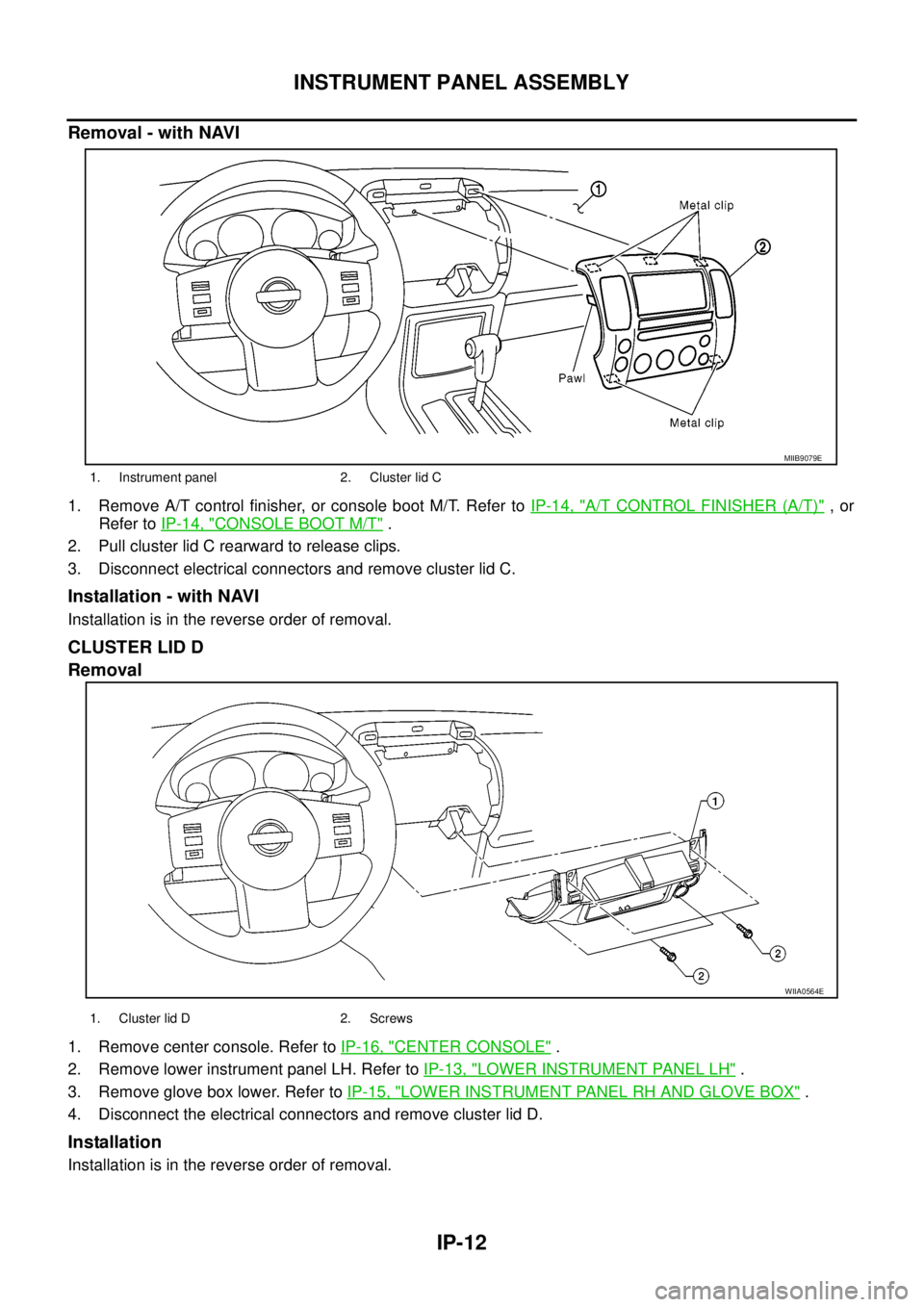
Removal - with NAVI
1. Remove A/T control finisher, or console boot M/T. Refer toIP-14, "A/T CONTROL FINISHER (A/T)",or
Refer toIP-14, "
CONSOLE BOOT M/T".
2. Pull cluster lid C rearward to release clips.
3. Disconnect electrical connectors and remove cluster lid C.
Installation - with NAVI
Installation is in the reverse order of removal.
CLUSTER LID D
Removal
1. Remove center console. Refer toIP-16, "CENTER CONSOLE".
2. Remove lower instrument panel LH. Refer toIP-13, "
LOWER INSTRUMENT PANEL LH".
3. Remove glove box lower. Refer toIP-15, "
LOWER INSTRUMENT PANEL RH AND GLOVE BOX".
4. Disconnect the electrical connectors and remove cluster lid D.
Installation
Installation is in the reverse order of removal.
1. Instrument panel 2. Cluster lid C
MIIB9079E
WIIA0564E
1. Cluster lid D 2. Screws