Page 2316 of 3171

SERVICE DATA AND SPECIFICATIONS (SDS)
MA-41
C
D
E
F
G
H
I
J
K
MA
B
MA
SERVICE DATA AND SPECIFICATIONS (SDS)PFP:00030
Standard and LimitELS001J8
BELT DEFLECTION
*: When engine is cold.
RESERVOIR TANK
Unit:kPa(bar,kg/cm2, psi)
ENGINE COOLANT CAPACITY (APPROXIMATE)
Unit: (lmp qt)
ENGINE OIL CAPACITY (APPROXIMATE)
Unit: (lmp qt) Applied beltBelt deflection with 98 N (10 kg, 22 lb) force applied* mm (in)
New Adjusted Limit for re-adjusting
A/C compressor, alternator and water
pump belt2.9 - 3.4 (0.114 - 0.134) 3.9 - 4.4 (0.154 - 0.173) 8.5 (0.335)
Power steering oil pump belt 4.6 - 5.4 (0.181 - 0.213) 7.1 - 7.7 (0.280 - 0.303) 11.3 (0.445)
Cap relief pressureStandard 98.2 - 117.8 (0.98 - 1.18, 1.0 - 1.2, 14 - 17)
Limit 59 (0.59, 0.6, 9)
Leakage test pressure 157 (1.57, 1.6, 23)
Engine coolant capacity (With reser-
voir tank at “MAX” level)LHD models 9.9 (8-3/4)
RHD models 10.2 (9)
Reservoir tank coolant capacity (At “MAX” level) 0.8 (3/4)
Drain and refillWith oil filter change 7.6 (6-5/8)
Without oil filter change 7.1 (6-1/4)
Dry engine (Overhaul)7.9 (7)
Page 2413 of 3171

MTC-26
AIR CONDITIONER CONTROL
AIR CONDITIONER CONTROL
PFP:27500
DescriptionEJS005FW
The front air control provides regulation of the vehicle's interior temperature. The system is based on the posi-
tion of the front air controls temperature switch selected by the driver. This is done by utilizing a microcom-
puter, also referred to as the front air control, which receives input signals from the following three sensors:
lIntake sensor
lPBR (Position Balanced Resistor).
The front air control uses these signals (including the set position of the temperature switch) to control:
lOutlet air volume
lAir temperature
lAir distribution
The front air control is used to select:
lOutlet air volume
lAir temperature/distribution
OperationEJS005FX
AIR MIX DOOR CONTROL
The air mix door is controlled so that in-vehicle temperature changed based on the position of the temperature
switch.
BLOWER SPEED CONTROL
Blower speed is controlled based on front blower switch settings.
When blower switch is turned, the blower motor starts and increases air flow volume each time the blower
switch is turned counterclockwise, and decreases air flow volume each time the blower switch is turned coun-
terclockwise.
When engine coolant temperature is low, the blower motor operation is delayed to prevent cool air from flow-
ing.
INTAKE DOORS CONTROL
The intake doors are controlled by the recirculation switch setting, and the mode (defroster) switch setting.
MODE DOOR CONTROL
The mode door is controlled by the position of the mode switch.
DEFROSTER DOOR CONTROL
The defroster door is controlled by: Turning the defroster dial to front defroster.
Page 2480 of 3171
TROUBLE DIAGNOSIS
MTC-93
C
D
E
F
G
H
I
K
L
MA
B
MTC
Insufficient HeatingEJS005GN
SYMPTOM: Insufficient heating
INSPECTION FLOW
*1 .MTC-53, "Operational Check".*2MTC-63, "Air Mix Door Motor Cir-
cuit".*3MTC-51, "
A/C System Self-diagno-
sis Function".
*4MTC-51, "
A/C System Self-diagno-
sis Function".*5MTC-71, "
Blower Motor Circuit".*6EC-103, "DTC P0117, P0118 ECT
SENSOR".
*7CO-7, "
Changing Engine Coolant".*8CO-13, "Checking Reservoir Tank
Cap".
MJIB0354E
Page 2492 of 3171

HEATER & COOLING UNIT ASSEMBLY
MTC-105
C
D
E
F
G
H
I
K
L
MA
B
MTC
Removal and InstallationEJS005GY
REMOVAL
1. Discharge the refrigerant from the A/C system. Refer toMTC-118, "Discharging Refrigerant".
2. Drain the coolant from the engine cooling system. Refer toCO-8, "
DRAINING ENGINE COOLANT".
3. Remove the cowl top extension. Refer toEI-20, "
Removal and Installation".
4. Remove the exhaust system. Refer toEX-3, "
Removal and Installation".
5. Disconnect the heater hoses from the heater core.
6. Disconnect the high/low pressure pipes from the expansion valve.
7. Move the two front seats to the rearmost position on the seat track.
8. Remove the instrument panel and console panel. Refer toIP-10, "
Removal and Installation".
9. Remove the steering column. Refer toPS-11, "
Removal and Installation".
10. Disconnect the instrument panel wire harness at the RH and LH in-line connector brackets, and the fuse
block (J/B) electrical connectors. Refer toPG-38, "
Harness Layout".
11. Disconnect the steering member from each side of the vehicle body.
12. Remove the heater and cooling unit assembly with it attached to the steering member, from the vehicle.
CAUTION:
Use care not to damage the seats and interior trim panels when removing the heater and cooling
unit assembly with it attached to the steering member.
13. Remove the heater and cooling unit assembly from the steering member.
INSTALLATION
Installation is in the reverse order of removal.
CAUTION:
lReplace the O-ring of the low-pressure pipe and high-pressure pipe with a new one, and apply
compressor oil to it when installing it.
lAfter charging the refrigerant, check for leaks.
NOTE:
lFill the engine cooling system with the specified coolant mixture. Refer toCO-8, "REFILLING ENGINE
COOLANT".
lRecharge the A/C system. Refer toMTC-118, "Evacuating System and Charging Refrigerant".
Page 2597 of 3171

PG-68
HARNESS
Wiring Diagram Codes (Cell Codes)
EKS00LJ9
Use the chart below to find out what each wiring diagram code stands for.
Refer to the wiring diagram code in the alphabetical index to find the location (page number) of each wiring
diagram.
Code Section Wiring Diagram Name
A/C,A ATC Auto Air Conditioner
A/C,M MTC Manual Air Conditioner
ABS BRC Anti-lock Brake System
APP1PW EC Accelerator Pedal Position Sensor 1 Power
APP2PW EC Accelerator Pedal Position Sensor 2 Power
APPS1 EC Accelerator Pedal Position Sensor 1
APPS2 EC Accelerator Pedal Position Sensor 2
APPS3 EC Accelerator Pedal Position Sensor
ASC/BS EC ASCD Brake Switch
ASC/SW EC ASCD Steering Switch
ASCBOF EC ASCD Brake Switch
ASCIND EC ASCD Indicator
AT/IND DI A/T Indicator Lamp
AUDIO AV Audio
AUTO/L LT Auto Lignt System
BACK/L LT Back-up Lamp
BOOST EC Turbocharger Boost Sensor
CAN AT CAN Communication Line
CAN EC CAN Communication Line
CAN LAN CAN System
CHARGE SC Charging System
CHIME DI Warning Chime
CIGER WW Cigarette Lighter
CKPS EC Crankshaft Position Sensor
CMPS EC Camshaft Position Sensor
COMBSW LT Combination Switch
COMM AV Audio Visual Communication Line
COMPAS DI Compass
COOL/F EC Cooling Fan Control
D/LOCK BL Power Door Lock
DIFLOC RFD Rear Final Drive
DEF GW Rear Window Defogger
DTRL LT Headlamp — With Daytime Running Light System
ECMRLY EC ECM Relay
ECTS EC Engine Coolant Temperature Sensor
EGRVLV EC EGR Volume Control System
EMNT EC Electronic Controlled Engine Mount Control Solenoid Valve
F/FOG LT Front Fog Lamp
F/PUMP EC Fuel Pump
FRPS EC Fuel Rail Pressure Sensor
FTS AT A/T Fluid Temperature Sensor
Page 2665 of 3171
RAX-2
[M226]
PRECAUTIONS
[M226]PRECAUTIONSPFP:00001
PrecautionsEDS003HT
lWhen installing the rubber bushings, the final tightening must be done under unladen condition and with
the tires on level ground. Oil will shorten the life of the rubber bushings, so wipe off any spilled oil immedi-
ately.
lUnladen condition means the fuel tank, engine coolant and lubricants are at the full secification. The
spare tire, jack, hand tools, and mats are in their designated positions.
lLock nuts are not reusable. Always use new lock nuts for installation. New lock nuts are pre-oiled, do not
apply any additional lubrication.
Page 2807 of 3171
RSU-2
PRECAUTIONS
PRECAUTIONS
PFP:00001
PrecautionsEES002JD
lWhen installing rubber parts, final tightening must be carried out under unladen condition* with
tires on ground.
*Fuel, radiator coolant, and engine oil are full. Spare tire, jack, hand tools, and mats are in their
designated positions. Oil will shorten the life of rubber bushings, so wipe off any spilled oil imme-
diately.
lLock nuts are not reusable. Always use new lock nuts for installation. New lock nuts are pre-oiled,
do not apply any additional lubrication.
Page 2810 of 3171

REAR SUSPENSION ASSEMBLY
RSU-5
C
D
F
G
H
I
J
K
L
MA
B
RSU
CAUTION:
When installing the components with rubber bushings, the final tightening of the nuts and bolts must
be done with the vehicle in an unladen condition (the fuel, engine coolant, and engine oil full; the
spare tire, jack, hand tools and mats in their designated positions) with the tires on the ground.
On-Vehicle Inspection and ServiceEES002JH
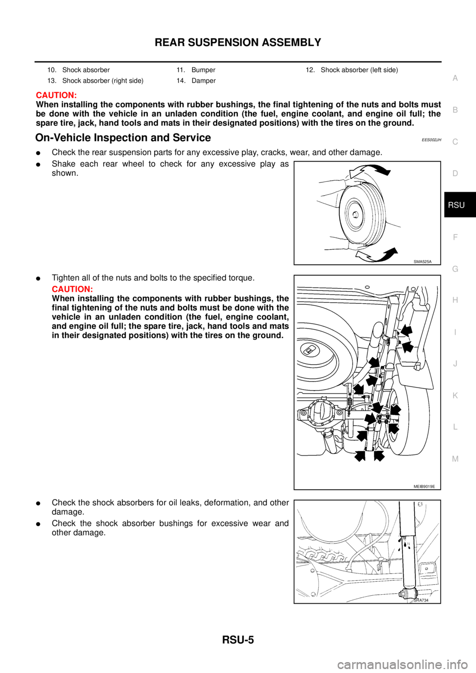
lCheck the rear suspension parts for any excessive play, cracks, wear, and other damage.
lShake each rear wheel to check for any excessive play as
shown.
lTighten all of the nuts and bolts to the specified torque.
CAUTION:
When installing the components with rubber bushings, the
final tightening of the nuts and bolts must be done with the
vehicle in an unladen condition (the fuel, engine coolant,
and engine oil full; the spare tire, jack, hand tools and mats
in their designated positions) with the tires on the ground.
lCheck the shock absorbers for oil leaks, deformation, and other
damage.
lCheck the shock absorber bushings for excessive wear and
other damage.
10. Shock absorber 11. Bumper 12. Shock absorber (left side)
13. Shock absorber (right side) 14. Damper
SMA525A
MEIB9019E
SRA734