2005 NISSAN NAVARA oil level
[x] Cancel search: oil levelPage 2318 of 3171
MT-1
MANUAL TRANSMISSION
C TRANSMISSION/TRANSAXLE
CONTENTS
D
E
F
G
H
I
J
K
L
M
SECTIONMT
A
B
MT
MANUAL TRANSMISSION
PRECAUTIONS .......................................................... 2
Service Notice or Precautions .................................. 2
PREPARATION ........................................................... 3
Special Service Tools ............................................... 3
Commercial Service Tools ........................................ 5
NOISE, VIBRATION AND HARSHNESS (NVH)
TROUBLESHOOTING ................................................ 6
NVH Troubleshooting Chart ..................................... 6
DESCRIPTION ............................................................ 7
Cross-Sectional View ............................................... 7
DOUBLE-CONE SYNCHRONIZER ...................... 8
TRIPLE-CONE SYNCHRONIZER ........................ 8
M/T OIL ....................................................................... 9
Changing M/T Oil ..................................................... 9
DRAINING ............................................................. 9
FILLING ................................................................. 9
Checking M/T Oil ...................................................... 9
OIL LEAKAGE AND OIL LEVEL ........................... 9
REAR OIL SEAL ...................................................... 10
Removal and Installation ........................................ 10
REMOVAL ........................................................... 10
INSTALLATION .................................................... 11
POSITION SWITCH .................................................. 12
Checking ................................................................ 12
BACK-UP LAMP SWITCH .................................. 12
PARK/NEUTRAL POSITION (PNP) SWITCH ..... 12SHIFT CONTROL ..................................................... 13
Removal and Installation ........................................ 13
COMPONENTS ................................................... 13
REMOVAL ........................................................... 13
INSTALLATION ................................................... 13
INSPECTION AFTER INSTALLATION ................ 14
AIR BREATHER HOSE ............................................ 15
Removal and Installation ........................................ 15
TRANSMISSION ASSEMBLY .................................. 16
Removal and Installation from Vehicle ................... 16
COMPONENTS ................................................... 16
REMOVAL ........................................................... 17
INSTALLATION ................................................... 18
Disassembly and Assembly .................................... 19
COMPONENTS ................................................... 19
DISASSEMBLY ................................................... 25
INSPECTION AFTER DISASSEMBLY ................ 40
ASSEMBLY ......................................................... 44
SERVICE DATA AND SPECIFICATIONS (SDS) ...... 67
General Specifications ............................................ 67
Gear End Play ........................................................ 68
Snap Rings ............................................................. 68
Baulk Ring Clearance ............................................. 69
Page 2319 of 3171

MT-2
PRECAUTIONS
PRECAUTIONS
PFP:00001
ServiceNoticeorPrecautionsECS00ICY
lDo not reuse transmission oil, once it has been drained.
lCheck oil level or replace oil with vehicle on level surface.
lDuring removal or installation, keep inside of transmission clear of dust or dirt.
lCheck for the correct installation status prior to removal or disassembly. If matching mark are required, be
certain they do not interfere with the function of the parts they are applied.
lIn principle, tighten bolts or nuts gradually in several steps working diagonally from inside to outside. If
tightening sequence is specified, use it.
lBe careful not to damage sliding surfaces and mating surfaces.
Page 2323 of 3171

MT-6
NOISE, VIBRATION AND HARSHNESS (NVH) TROUBLESHOOTING
NOISE, VIBRATION AND HARSHNESS (NVH) TROUBLESHOOTING
PFP:00003
NVH Troubleshooting ChartECS00ID1
Use the chart below to help you find the cause of the symptom. The numbers indicate the order of the inspec-
tion. If necessary, repair or replace these parts.
Reference pageMT-9MT-19MT-13MT-23MT-21
SUSPECTED PARTS
(Possible cause)
OIL (Oil level is low.)
OIL(Wrongoil.)
OIL (Oil level is high.)
GASKET (Damaged)
OIL SEAL (Worn or damaged)
SHIFT CONTROL LINKAGE (Worn)
CHECK PLUG RETURN SPRING AND CHECK BALL (Worn or damaged)
SHIFT FORK (Worn)
GEAR (Worn or damaged)
BEARING (Worn or damaged)
BAULK RING (Worn or damaged)
INSERT SPRING (Damaged)
SymptomsNoise 1 2 3 3
Oilleakage 3122
Hard to shift or will not shift 1 1 2 2 2
Jumpsoutofgear 1122
Page 2326 of 3171

M/T OIL
MT-9
D
E
F
G
H
I
J
K
L
MA
B
MT
M/T OILPFP:KLD20
Changing M/T OilECS00ID3
DRAINING
1. Start engine and let it run to warm up transmission.
2. Stop engine. Remove drain plug and gasket and then drain oil.
3. Set a gasket on drain plug and install it to transmission case. Tighten drain plug to the specified torque.
Refer toMT-19, "
Case Components".
CAUTION:
Do no reuse gasket.
FILLING
1. Remove filler plug and gasket. Fill with new oil until oil level reaches the specified limit near filler plug
mounting hole.
2. After refilling oil, check oil level. Set a gasket to filler plug, then install it to transmission case. Tighten filler
plug to the specified torque. Refer toMT-19, "
Case Components".
CAUTION:
Do no reuse gasket.
Checking M/T OilECS00ID4
OIL LEAKAGE AND OIL LEVEL
lMake sure that oil is not leaking from transmission or around it.
lCheck oil level from filler plug mounting hole as shown in the fig-
ure.
CAUTION:
Do not start engine while checking oil level.
lSet a gasket on filler plug and install it to transmission case.
Tighten filler plug to the specified torque. Refer toMT-19, "
Case
Components".
CAUTION:
Do not reuse gasket.Oil grade and viscosity: Refer toMA-14, "
Fluids and Lubricants".
Oil capacity
2WD models:
Approx. 3.99 (7 Imp pt)
4WD models:
Approx. 4.32 (7-5/8 Imp pt)
PCIB0268E
Page 2328 of 3171
REAR OIL SEAL
MT-11
D
E
F
G
H
I
J
K
L
MA
B
MT
INSTALLATION
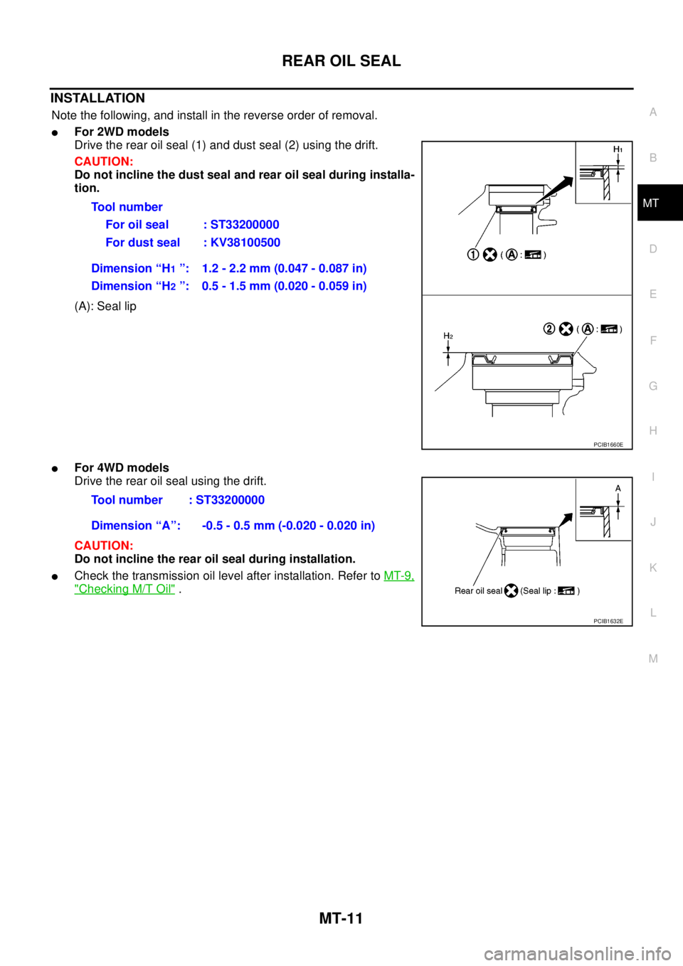
Note the following, and install in the reverse order of removal.
lFor 2WD models
Drive the rear oil seal (1) and dust seal (2) using the drift.
CAUTION:
Do not incline the dust seal and rear oil seal during installa-
tion.
(A): Seal lip
lFor 4WD models
Drive the rear oil seal using the drift.
CAUTION:
Do not incline the rear oil seal during installation.
lCheck the transmission oil level after installation. Refer toMT-9,
"Checking M/T Oil". Tool number
For oil seal : ST33200000
For dust seal : KV38100500
Dimension “H
1”: 1.2 - 2.2 mm (0.047 - 0.087 in)
Dimension “H
2”: 0.5 - 1.5 mm (0.020 - 0.059 in)
PCIB1660E
Tool number : ST33200000
Dimension “A”: -0.5 - 0.5 mm (-0.020 - 0.020 in)
PCIB1632E
Page 2335 of 3171
MT-18
TRANSMISSION ASSEMBLY
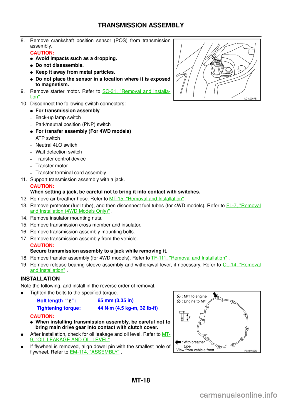
8. Remove crankshaft position sensor (POS) from transmission
assembly.
CAUTION:
lAvoid impacts such as a dropping.
lDo not disassemble.
lKeep it away from metal particles.
lDo not place the sensor in a location where it is exposed
to magnetism.
9. Remove starter motor. Refer toSC-31, "
Removal and Installa-
tion".
10. Disconnect the following switch connectors:
lFor transmission assembly
–Back-up lamp switch
–Park/neutral position (PNP) switch
lFor transfer assembly (For 4WD models)
–AT P s w i t c h
–Neutral 4LO switch
–Wait detection switch
–Transfer control device
–Transfer motor
–Transfer terminal cord assembly
11. Support transmission assembly with a jack.
CAUTION:
When setting a jack, be careful not to bring it into contact with switches.
12. Remove air breather hose. Refer toMT-15, "
Removal and Installation".
13. Remove protector (fuel tube), and then disconnect fuel tubes (for 4WD models). Refer toFL-7, "
Removal
and Installation (4WD Models Only)".
14. Remove insulator mounting nuts.
15. Remove transmission cross member and insulator.
16. Remove transmission assembly mounting bolts.
17. Remove transmission assembly from the vehicle.
CAUTION:
Secure transmission assembly to a jack while removing it.
18. Remove transfer assembly (for 4WD models). Refer toTF-111, "
Removal and Installation".
19. Remove release bearing sleeve assembly and withdrawal lever, if necessary. Refer toCL-14, "
Removal
and Installation".
INSTALLATION
Note the following, and install in the reverse order of removal.
lTighten the bolts to the specified torque.
CAUTION:
lWhen installing transmission assembly, be careful not to
bring main drive gear into contact with clutch cover.
lAfter installation, check for oil leakage and oil level. Refer toMT-
9, "OIL LEAKAGE AND OIL LEVEL".
lIf flywheel is removed, align dowel pin with the smallest hole of
flywheel. Refer toEM-114, "
ASSEMBLY".
LCIA0367E
Bolt length “ ”:85 mm (3.35 in)
Tightening torque: 44 N·m (4.5 kg-m, 32 lb-ft)
PCIB1603E
Page 2513 of 3171
MTC-126
REFRIGERANT LINES
BREAK-IN OPERATION
When replacing compressor clutch assembly, always conduct the break-in operation. This is done by engag-
ing and disengaging the clutch about 30 times. Break-in operation raises the level of transmitted torque.
Removal and Installation for Low-pressure Flexible HoseEJS005HE
REMOVAL
1. Remove the engine room cover using power tools.
2. Remove the engine air cleaner and air ducts. Refer toEM-15, "
AIR CLEANER AND AIR DUCT".
3. Remove the cowl top extension. Refer toEI-20, "
COWL TOP".
4. Discharge the refrigerant. Refer toMTC-118, "
HFC-134a (R-134a) Service Procedure".
CAUTION:
Cap or wrap the joint of the pipe with suitable material such as vinyl tape to avoid the entry of air.
5. Remove the low-pressure flexible hose. Refer toMTC-120, "
Components".
INSTALLATION
Installation is in the reverse order of removal.
Refer toMTC-120, "
Components".
CAUTION:
lReplace the O-ring of the low-pressure flexible hose with a new one, then apply compressor oil to
it when installing it.
lAfter charging refrigerant, check for leaks.
Removal and Installation for High-pressure Flexible HoseEJS005HF
REMOVAL
1. Remove the engine under cover.
2. Remove the engine air cleaner and air ducts. Refer toEM-15, "
AIR CLEANER AND AIR DUCT"
3. Discharge the refrigerant. Refer toMTC-118, "HFC-134a (R-134a) Service Procedure".
4. Remove the high-pressure flexible hose. Refer toMTC-120, "
Components".
CAUTION:
Cap or wrap the joint of the pipe with suitable material such as vinyl tape to avoid the entry of air.
INSTALLATION
Installation is in the reverse order of removal.
Refer toMTC-120, "
Components".
CAUTION:
lReplace the O-ring of the high-pressure flexible hose with a new one, then apply compressor oil to
it when installing it.
lAfter charging refrigerant, check for leaks.
Removal and Installation for High-pressure PipeEJS005HG
REMOVAL
1. Remove the cowl top extension. Refer toEI-20, "COWL TOP".
2. Disconnect the battery negative cable.
3. Reposition the IPDM E/R aside.
4. Remove the front right wheel and tire assembly. Refer toWT-5, "
Rotation".
5. Position aside the front floor insulator.
6. Discharge the refrigerant. Refer toMTC-118, "
HFC-134a (R-134a) Service Procedure".
7. Remove the low pressure pipe. Refer toMTC-127, "
Removal and Installation for Low-pressure Pipe".
8. Remove the high-pressure pipe. Refer toMTC-120, "
Components".
CAUTION:
Cap or wrap the joint of the pipe with suitable material such as vinyl tape to avoid the entry of air.
INSTALLATION
Installation is in the reverse order of removal.
Refer toMTC-120, "
Components".
Page 2628 of 3171
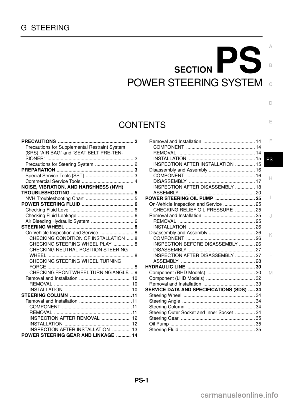
PS-1
POWER STEERING SYSTEM
G STEERING
CONTENTS
C
D
E
F
H
I
J
K
L
M
SECTIONPS
A
B
PS
POWER STEERING SYSTEM
PRECAUTIONS .......................................................... 2
Precautions for Supplemental Restraint System
(SRS)“AIRBAG”and“SEATBELTPRE-TEN-
SIONER” .................................................................. 2
Precautions for Steering System .............................. 2
PREPARATION ........................................................... 3
Special Service Tools [SST] ..................................... 3
Commercial Service Tools ........................................ 4
NOISE, VIBRATION, AND HARSHNESS (NVH)
TROUBLESHOOTING ................................................ 5
NVH Troubleshooting Chart ..................................... 5
POWER STEERING FLUID ........................................ 6
Checking Fluid Level ................................................ 6
Checking Fluid Leakage ........................................... 6
Air Bleeding Hydraulic System ................................. 6
STEERING WHEEL .................................................... 8
On-Vehicle Inspection and Service .......................... 8
CHECKING CONDITION OF INSTALLATION ...... 8
CHECKING STEERING WHEEL PLAY ................ 8
CHECKING NEUTRAL POSITION STEERING
WHEEL ................................................................. 8
CHECKING STEERING WHEEL TURNING
FORCE .................................................................. 8
CHECKING FRONT WHEEL TURNING ANGLE..... 9
Removal and Installation ........................................ 10
REMOVAL ........................................................... 10
INSTALLATION ................................................... 10
STEERING COLUMN ................................................11
Removal and Installation ......................................... 11
COMPONENT ...................................................... 11
REMOVAL ............................................................ 11
INSPECTION AFTER REMOVAL ....................... 12
INSTALLATION ................................................... 12
INSPECTION AFTER INSTALLATION ............... 13
POWER STEERING GEAR AND LINKAGE ............ 14Removal and Installation ........................................ 14
COMPONENT ..................................................... 14
REMOVAL ........................................................... 14
INSTALLATION ................................................... 15
INSPECTION AFTER INSTALLATION ................ 15
Disassembly and Assembly .................................... 16
COMPONENT ..................................................... 16
DISASSEMBLY ................................................... 17
INSPECTION AFTER DISASSEMBLY ................ 18
ASSEMBLY ......................................................... 20
POWER STEERING OIL PUMP ............................... 25
On-Vehicle Inspection and Service ......................... 25
CHECKING RELIEF OIL PRESSURE ................ 25
Removal and Installation ........................................ 25
REMOVAL ........................................................... 25
INSTALLATION ................................................... 26
Disassembly and Assembly .................................... 26
COMPONENT ..................................................... 26
INSPECTION BEFORE DISASSEMBLY ............. 26
DISASSEMBLY ................................................... 27
INSPECTION AFTER DISASSEMBLY ................ 27
ASSEMBLY ......................................................... 28
HYDRAULIC LINE .................................................... 30
Component (RHD Models) ..................................... 30
Component (LHD Models) ...................................... 32
Removal and Installation ........................................ 33
SERVICE DATA AND SPECIFICATIONS (SDS) ...... 34
Steering Wheel ....................................................... 34
Steering Angle ........................................................ 34
Steering Column ..................................................... 34
Steering Outer Socket and Inner Socket ................ 34
Steering Gear ......................................................... 35
Oil Pump ................................................................. 35
Steering Fluid .......................................................... 35