2005 NISSAN NAVARA oil level
[x] Cancel search: oil levelPage 2633 of 3171

PS-6
POWER STEERING FLUID
POWER STEERING FLUID
PFP:KLF20
Checking Fluid LevelEGS001LD
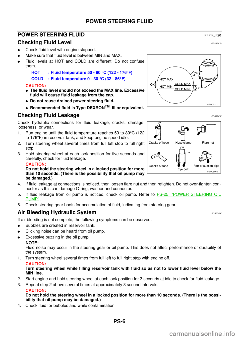
lCheck fluid level with engine stopped.
lMake sure that fluid level is between MIN and MAX.
lFluid levels at HOT and COLD are different. Do not confuse
them.
CAUTION:
lThe fluid level should not exceed the MAX line. Excessive
fluid will cause fluid leakage from the cap.
lDo not reuse drained power steering fluid.
lRecommended fluid is Type DEXRONTMIII or equivalent.
Checking Fluid LeakageEGS001LE
Check hydraulic connections for fluid leakage, cracks, damage,
looseness, or wear.
1. Run engine until the fluid temperature reaches 50 to 80°C(122
to 176°F) in reservoir tank, and keep engine speed idle.
2. Turn steering wheel several times from full left stop to full right
stop.
3. Hold steering wheel at each lock position for five seconds and
carefully, check for fluid leakage.
CAUTION:
Do not hold the steering wheel in a locked position for more
than 10 seconds. (There is the possibility that oil pump may
be damaged.)
4. If fluid leakage at connections is noticed, then loosen flare nut and then retighten. Do not over-tighten con-
nector as this can damage O-ring, washer and connector.
5. If fluid leakage from oil pump is noticed, check oil pump. Refer toPS-25, "
POWER STEERING OIL
PUMP".
6. Check steering gear boots for accumulation of fluid, indicating from steering gear.
Air Bleeding Hydraulic SystemEGS001LF
If air bleeding is not complete, the following symptoms can be observed.
lBubbles are created in reservoir tank.
lClicking noise can be heard from oil pump.
lExcessive buzzing in the oil pump
NOTE:
Fluid noise may occur in the steering gear or oil pump. This does not affect performance or durability of
the system.
1. Turn steering wheel several times from full left to full right stop with engine off.
CAUTION:
Turn steering wheel while filling reservoir tank with fluid so as not to lower fluid level below the
MIN line.
2. Start engine and hold steering wheel at each lock position for 3 seconds at idle to check for fluid leakage.
3. Repeat step 2 above several times at approximately 3 second intervals.
CAUTION:
Do not hold the steering wheel in a locked position for more than 10 seconds. (There is the possi-
bility that oil pump may be damaged.)
4. Check fluid for bubbles and while contamination.HOT : Fluid temperature 50 - 80°C (122 - 176°F)
COLD : Fluid temperature 0 - 30°C(32-86°F)
SGIA0232J
SGIA0506E
Page 2635 of 3171

PS-8
STEERING WHEEL
STEERING WHEEL
PFP:48430
On-Vehicle Inspection and ServiceEGS001LG
CHECKING CONDITION OF INSTALLATION
lCheck installation conditions of steering gear assembly, front suspension assembly, axle and steering col-
umn assembly.
lCheck if movement exists when steering wheel is moved up and down, to the left and right and to the axial
direction.
lCheck steering gear assembly mounting bolts and nuts for looseness. Refer toPS-14, "COMPONENT".
CHECKING STEERING WHEEL PLAY
lTurn steering wheel so that front wheels come to the straight-ahead position. Start engine and lightly turn
steering wheel to the left and right until front wheels start to move. Measure steering wheel movement on
the outer circumference.
lWhen the measurement value is outside the standard value, check backlash for each joint of steering col-
umn assembly and installation condition of steering gear assembly.
CHECKING NEUTRAL POSITION STEERING WHEEL
lMake sure that steering gear assembly, steering column assembly and steering wheel are installed in the
correct position.
lPerform neutral position inspection after wheel alignment. Refer toFSU-7, "Front Wheel Alignment".
lSet vehicle to the straight-ahead position and confirm steering wheel is in the neutral position.
lLoosen outer socket lock nut and turn inner socket to left and right equally to make fine adjustment if
steering wheel is not in the neutral position.
CHECKING STEERING WHEEL TURNING FORCE
1. Park vehicle on a level and dry surface, set parking brake.
2. Start engine.
3. Bring power steering fluid up to adequate operating temperature. [Make sure temperature of fluid is
approximately 50 to 80°C(122to176°F).]
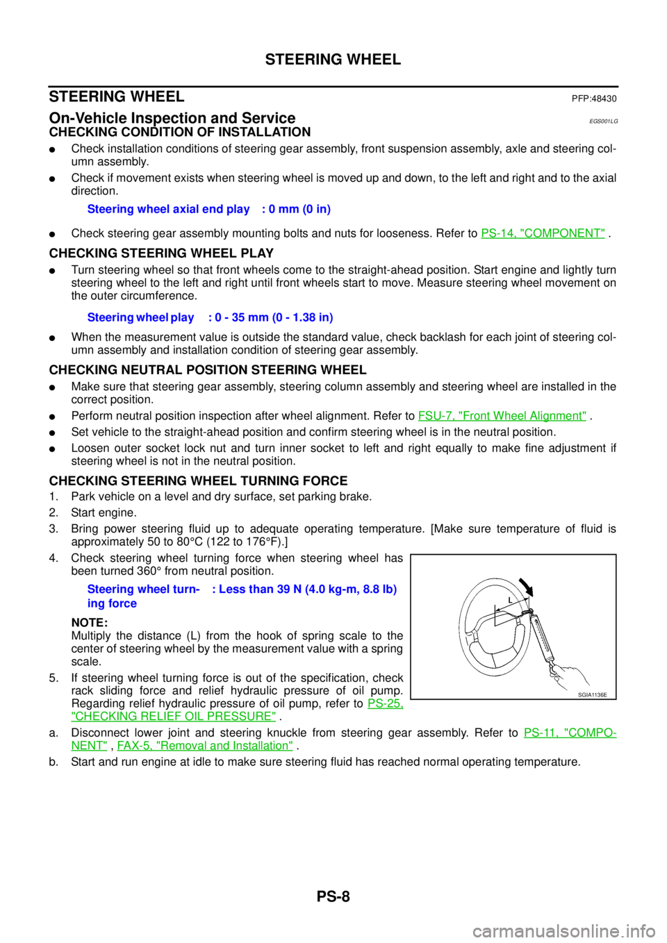
4. Check steering wheel turning force when steering wheel has
been turned 360°from neutral position.
NOTE:
Multiply the distance (L) from the hook of spring scale to the
center of steering wheel by the measurement value with a spring
scale.
5. If steering wheel turning force is out of the specification, check
rack sliding force and relief hydraulic pressure of oil pump.
Regarding relief hydraulic pressure of oil pump, refer toPS-25,
"CHECKING RELIEF OIL PRESSURE".
a. Disconnect lower joint and steering knuckle from steering gear assembly. Refer toPS-11, "
COMPO-
NENT",FAX-5, "Removal and Installation".
b. Start and run engine at idle to make sure steering fluid has reached normal operating temperature.Steering wheel axial end play : 0 mm (0 in)
Steering wheel play : 0 - 35 mm (0 - 1.38 in)
Steering wheel turn-
ing force: Less than 39 N (4.0 kg-m, 8.8 lb)
SGIA1136E
Page 2665 of 3171
![NISSAN NAVARA 2005 Repair Workshop Manual RAX-2
[M226]
PRECAUTIONS
[M226]PRECAUTIONSPFP:00001
PrecautionsEDS003HT
lWhen installing the rubber bushings, the final tightening must be done under unladen condition and with
the tires on level grou NISSAN NAVARA 2005 Repair Workshop Manual RAX-2
[M226]
PRECAUTIONS
[M226]PRECAUTIONSPFP:00001
PrecautionsEDS003HT
lWhen installing the rubber bushings, the final tightening must be done under unladen condition and with
the tires on level grou](/manual-img/5/57362/w960_57362-2664.png)
RAX-2
[M226]
PRECAUTIONS
[M226]PRECAUTIONSPFP:00001
PrecautionsEDS003HT
lWhen installing the rubber bushings, the final tightening must be done under unladen condition and with
the tires on level ground. Oil will shorten the life of the rubber bushings, so wipe off any spilled oil immedi-
ately.
lUnladen condition means the fuel tank, engine coolant and lubricants are at the full secification. The
spare tire, jack, hand tools, and mats are in their designated positions.
lLock nuts are not reusable. Always use new lock nuts for installation. New lock nuts are pre-oiled, do not
apply any additional lubrication.
Page 2672 of 3171
![NISSAN NAVARA 2005 Repair Workshop Manual AXLE SHAFT
RAX-9
[M226]
C
E
F
G
H
I
J
K
L
MA
B
RAX
INSPECTION AFTER REMOVAL
Axle Shaft Bearing and Cup
lCheck that the axle shaft bearing and cup roll freely and are free from noise, cracks, pitting a NISSAN NAVARA 2005 Repair Workshop Manual AXLE SHAFT
RAX-9
[M226]
C
E
F
G
H
I
J
K
L
MA
B
RAX
INSPECTION AFTER REMOVAL
Axle Shaft Bearing and Cup
lCheck that the axle shaft bearing and cup roll freely and are free from noise, cracks, pitting a](/manual-img/5/57362/w960_57362-2671.png)
AXLE SHAFT
RAX-9
[M226]
C
E
F
G
H
I
J
K
L
MA
B
RAX
INSPECTION AFTER REMOVAL
Axle Shaft Bearing and Cup
lCheck that the axle shaft bearing and cup roll freely and are free from noise, cracks, pitting and wear.
Replace if necessary.
Axle Shaft Retainer
lCheck for deformation and cracks. Replace if necessary.
Rear Axle Case
lCheck the exterior and inner machined surfaces for deformation and cracks. Replace if necessary.
INSTALLATION
Installation is in the reverse order of removal.
When installing pay attention to following points:
lInstall a new shaft guide and a new oil seal into the rear axle case.
CAUTION:
lDo not reuse the axle oil seal. The axle oil seal must be replaced every time the axle shaft assem-
bly is removed from the axle shaft housing.
lWhen installing oil seals, apply multi-purpsose grease to oil seal lips.
lInstall four new lock nuts to secure the axle shaft assembly to the rear axle case, and tighten lock nuts to
the specified torque. Refer toRAX-7, "
Removal and Installation".
lReinstall the rear brake drum. Refer toBR-31, "Removal and Installation of Drum Brake Assembly".
lAdjust the differential gear oil level.
Refer toRFD-9, "
DIFFERENTIAL GEAR OIL", for M226 without LD.
Refer toRFD-9, "
DIFFERENTIAL GEAR OIL", for M226 with LD.
lReinstall the wheel. Refer toWT-5, "Rotation".
DISASSEMBLY
1. Remove the ABS sensor rotor. Refer toBRC-39, "SENSOR ROTOR".
2. Remove the snap ring from the axle shaft using a suitable snap ring pliers.
3. Secure the axle shaft in a suitable vise as shown, and use a
brass hammer to remove studs (4) from the axle shaft retainer.
CAUTION:
lMount the axle shaft using a soft jaw vise to avoid dam-
aging the axle shaft retainer.
MDIB9051E
Page 2704 of 3171

RFD-1
REAR FINAL DRIVE
D DRIVELINE/AXLE
CONTENTS
C
E
F
G
H
I
J
K
L
M
SECTIONRFD
A
B
RFD
REAR FINAL DRIVE
WITH LIMITED SLIP DIFFERENTIAL
PRECAUTIONS .......................................................... 3
Limited Slip Differential (LSD) Performance Judge-
ment ......................................................................... 3
METHOD FOR TROUBLESHOOTING ................. 3
Service Notice or Precautions .................................. 3
PREPARATION ........................................................... 4
Special Service Tools ............................................... 4
Commercial Service Tools ........................................ 5
NOISE, VIBRATION, AND HARSHNESS (NVH)
TROUBLESHOOTING ................................................ 7
NVH Troubleshooting Chart ..................................... 7
DESCRIPTION ............................................................ 8
Cross-Sectional View ............................................... 8
DIFFERENTIAL GEAR OIL ........................................ 9
Changing Differential Gear Oil ................................. 9
DRAINING ............................................................. 9
FILLING ................................................................. 9
Checking Differential Gear Oil .................................. 9
OIL LEAKAGE AND OIL LEVEL ........................... 9
FRONT OIL SEAL .................................................... 10
Removal and Installation ........................................ 10
REMOVAL ........................................................... 10
INSTALLATION .................................................... 11
CARRIER COVER .................................................... 13
Removal and Installation ........................................ 13
REMOVAL ........................................................... 13
INSTALLATION ................................................... 13
REAR FINAL DRIVE ASSEMBLY ............................ 14
Removal and Installation ........................................ 14
REMOVAL ........................................................... 14
INSTALLATION ................................................... 14
Disassembly and Assembly ................................... 15
COMPONENTS .................................................. 15
ASSEMBLY INSPECTION AND ADJUSTMENT... 16
DISASSEMBLY ................................................... 19
INSPECTION AFTER DISASSEMBLY ............... 22
SELECTION ADJUSTING WASHERS ............... 23
ASSEMBLY ......................................................... 24SERVICE DATA AND SPECIFICATIONS (SDS) ...... 31
General Specifications ............................................ 31
Inspection and Adjustment ..................................... 31
PRELOAD TORQUE ........................................... 31
BACKLASH ......................................................... 31
COMPANION FLANGE RUNOUT ....................... 31
SELECTIVE PARTS ............................................ 32
WITH ELECTRONIC LOCKING DIFFEREN-
TIAL
PRECAUTIONS ........................................................ 33
Precautions for Supplemental Restraint System
(SRS)“AIRBAG”and“SEATBELTPRE-TEN-
SIONER” ................................................................. 33
Precautions for Differential Case Assembly and Dif-
ferential Lock Control Unit Replacement ................ 33
CHECK DIFF LOCK INDICATOR LAMP ............. 33
METHOD FOR ADJUSTMENT ........................... 34
Precautions ............................................................. 34
Service Notice or Precaution .................................. 35
Wiring Diagrams and Trouble Diagnosis ................ 35
PREPARATION ......................................................... 36
Special Service Tools ............................................. 36
Commercial Service Tools ...................................... 37
NOISE, VIBRATION AND HARSHNESS (NVH)
TROUBLESHOOTING .............................................. 39
NVH Troubleshooting Chart ................................... 39
DIFFERENTIAL GEAR OIL ...................................... 40
Changing Differential Gear Oil ................................ 40
DRAINING ........................................................... 40
FILLING ............................................................... 40
Checking Differential Gear Oil ................................ 40
OIL LEAKAGE AND OIL LEVEL ......................... 40
DIFFERENTIAL LOCK SYSTEM .............................. 41
Cross-sectional View .............................................. 41
Differential Lock Operation ..................................... 42
System Description ................................................. 42
DIFFERENTIAL LOCK SOLENOID .................... 42
DIFFERENTIAL LOCK POSITION SWITCH ....... 42
Page 2706 of 3171
![NISSAN NAVARA 2005 Repair Workshop Manual PRECAUTIONS
RFD-3
[WITH LIMITED SLIP DIFFERENTIAL]
C
E
F
G
H
I
J
K
L
MA
B
RFD
[WITH LIMITED SLIP DIFFERENTIAL]PRECAUTIONSPFP:00001
Limited Slip Differential (LSD) Performance JudgementEDS003IG
lInspec NISSAN NAVARA 2005 Repair Workshop Manual PRECAUTIONS
RFD-3
[WITH LIMITED SLIP DIFFERENTIAL]
C
E
F
G
H
I
J
K
L
MA
B
RFD
[WITH LIMITED SLIP DIFFERENTIAL]PRECAUTIONSPFP:00001
Limited Slip Differential (LSD) Performance JudgementEDS003IG
lInspec](/manual-img/5/57362/w960_57362-2705.png)
PRECAUTIONS
RFD-3
[WITH LIMITED SLIP DIFFERENTIAL]
C
E
F
G
H
I
J
K
L
MA
B
RFD
[WITH LIMITED SLIP DIFFERENTIAL]PRECAUTIONSPFP:00001
Limited Slip Differential (LSD) Performance JudgementEDS003IG
lInspection is required when detecting any noise or malfunction while driving or turning. Improper condition
of oil or differential case assembly is suspected. Refer toRFD-3, "
METHOD FOR TROUBLESHOOTING"
.
METHOD FOR TROUBLESHOOTING
1. Check differential gear oil level and differential gear oil leakage. Refer toRFD-9, "Checking Differential
Gear Oil".
2. Changing differential gear oil. Refer toRFD-9, "
Changing Differential Gear Oil".
3. Start engine. Drive for 10 min.
4. Again changing differential gear oil. Refer toRFD-9, "
Changing Differential Gear Oil".
5. Start engine. Drive for 10 min. Check if any noise or improper oil condition is detected.
lIf OK, check differential gear oil level and differential gear oil leakage. Refer toRFD-9, "Checking Differ-
ential Gear Oil".
lIf NG, replace differential case assembly after checking each part of final drive. Refer toRFD-15, "Dis-
assembly and Assembly".
Service Notice or PrecautionsEDS0038Z
lCheck for the correct installation status prior to removal or disassembly. If matching marks are required,
be certain they do not interfere with the function of the parts when applied.
lOverhaul should be done in a clean work area, it is preferable to work in dust proof area.
lBefore disassembly completely remove sand and mud from the exterior of the unit, preventing them from
entering into the unit during disassembly or assembly.
lCheck appearance of the disassembled parts for damage, deformation, and unusual wear. Replace them
with new ones if necessary.
lGaskets, seals and O-rings should be replaced any time the unit is disassembled.
lIn principle, tighten bolts or nuts gradually in several steps working diagonally from inside to outside. If
tightening sequence is specified, observe it.
lClean and flush the parts sufficiently and blow-dry them.
lBe careful not to damage sliding surfaces and mating surfaces.
lWhen applying sealant, remove the old sealant from the mounting surface; then remove any moisture, oil,
and foreign materials from the application and mounting surfaces.
lAlways use shop paper for cleaning the inside of components.
lAvoid using cotton gloves or shop rags to prevent entering of lint.
lDuring assembly, observe the specified tightening torque, and apply new differential gear oil, petroleum
jelly, or multi-purpose grease as specified.
Page 2712 of 3171
![NISSAN NAVARA 2005 Repair Workshop Manual DIFFERENTIAL GEAR OIL
RFD-9
[WITH LIMITED SLIP DIFFERENTIAL]
C
E
F
G
H
I
J
K
L
MA
B
RFD
DIFFERENTIAL GEAR OILPFP:KLD30
Changing Differential Gear OilEDS00394
DRAINING
1. Stop engine.
2. Remove drain p NISSAN NAVARA 2005 Repair Workshop Manual DIFFERENTIAL GEAR OIL
RFD-9
[WITH LIMITED SLIP DIFFERENTIAL]
C
E
F
G
H
I
J
K
L
MA
B
RFD
DIFFERENTIAL GEAR OILPFP:KLD30
Changing Differential Gear OilEDS00394
DRAINING
1. Stop engine.
2. Remove drain p](/manual-img/5/57362/w960_57362-2711.png)
DIFFERENTIAL GEAR OIL
RFD-9
[WITH LIMITED SLIP DIFFERENTIAL]
C
E
F
G
H
I
J
K
L
MA
B
RFD
DIFFERENTIAL GEAR OILPFP:KLD30
Changing Differential Gear OilEDS00394
DRAINING
1. Stop engine.
2. Remove drain plug and drain gear oil.
3. Apply sealant to drain plug. Install drain plug to final drive
assembly and tighten to the specified torque. Refer toRFD-15,
"COMPONENTS".
FILLING
1. Remove filler plug. Fill with new gear oil until oil level reaches
the specified limit near filler plug hole.
2. After refilling oil, check oil level. Apply sealant to filler plug.
Install filler plug to final drive assembly and tighten to the speci-
fied torque. Refer toRFD-15, "
COMPONENTS".
Checking Differential Gear OilEDS00395
OIL LEAKAGE AND OIL LEVEL
1. Make sure that gear oil is not leaking from final drive assembly or around it.
2. Check oil level from filler plug hole as shown.
CAUTION:
Do not start engine while checking oil level.
3. Apply sealant to filler plug. Install filler plug to final drive assem-
bly and tighten to the specified torque. Refer toRFD-15, "
COM-
PONENTS".
PDIA1038E
OilgradeandViscosity:
Refer toMA-14, "
Fluids and Lubricants".
Oil capacity:
Approx. 2.01 (3-1/2pt)
PDIA1039E
PDIA1039E
Page 2715 of 3171
![NISSAN NAVARA 2005 Repair Workshop Manual RFD-12
[WITH LIMITED SLIP DIFFERENTIAL]
FRONT OIL SEAL
4. Rotate the drive pinion using Tool. Rotating torque should be
equaltothereadingrecordedinstep4aboveduringremoval
plus an additional 0.56 N·m NISSAN NAVARA 2005 Repair Workshop Manual RFD-12
[WITH LIMITED SLIP DIFFERENTIAL]
FRONT OIL SEAL
4. Rotate the drive pinion using Tool. Rotating torque should be
equaltothereadingrecordedinstep4aboveduringremoval
plus an additional 0.56 N·m](/manual-img/5/57362/w960_57362-2714.png)
RFD-12
[WITH LIMITED SLIP DIFFERENTIAL]
FRONT OIL SEAL
4. Rotate the drive pinion using Tool. Rotating torque should be
equaltothereadingrecordedinstep4aboveduringremoval
plus an additional 0.56 N·m (5 in-lb).
5. If the rotating torque is low, continue to tighten the drive pinion
lock nut in 6.8 N·m (5 ft-lb) increments without overtightening.
Refer toRFD-15, "
COMPONENTS". Tighten until proper rotat-
ing torque is achieved.
CAUTION:
lDo not loosen the drive pinion lock nut to decrease drive
pinion rear bearing rotating torque.
lDo not exceed specified rotating preload torque. If preload torque or rotating torque is exceeded
a new collapsible spacer must be installed.
lDo not exceed maximum tightening torque. If maximum tightening torque is reached prior to
reaching the required rotating torque, the collapsible spacer may have been damaged. Replace
the collapsible spacer.
6. Check the gear oil level. Refer toRFD-9, "
Checking Differential Gear Oil".
7. Install the remaining components in the reverse order of removal.Tool number : ST3127S000
PDIA0309E