2005 MITSUBISHI 380 ECU
[x] Cancel search: ECUPage 1272 of 1500
MAINTENANCE SERVICE
GENERAL00-51
18. SUSPENSION SYSTEM (INSPECT FOR
LOOSENESS AND DAMAGE)
M1001009600048
Visually inspect the front/rear suspension components for dete-
rioration and damage. Re-tighten the front/rear suspension
components retaining bolts to specified torque.
19. SRS AIR BAG (INSPECT FOR SRS SYSTEM)M1001003700326
The entire SRS including air bag and pre-tensioner seat belt
must be inspected by an authorized MITSUBISHI MOTORS
dealer 10 years.
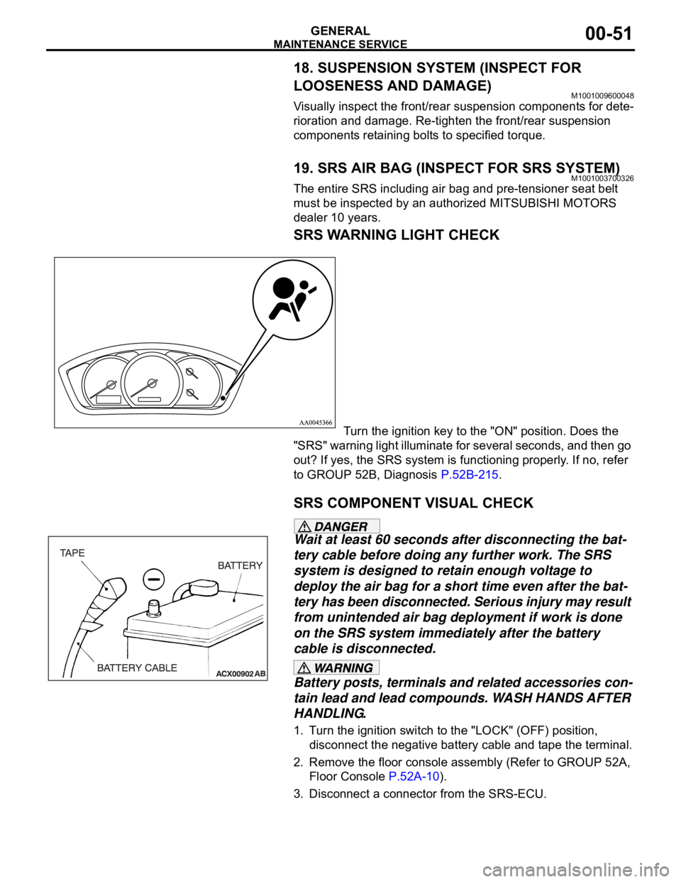
SRS WARNING LIGHT CHECK
Turn the ignition key to the "ON" position. Does the
"SRS" warning light illuminate for several seconds, and then go
out? If yes, the SRS system is functioning properly. If no, refer
to GROUP 52B, Diagnosis P.52B-215.
SRS COMPONENT VISUAL CHECK
Wait at least 60 seconds after disconnecting the bat-
tery cable before doing any further work. The SRS
system is designed to retain enough voltage to
deploy the air bag for a short time even after the bat-
tery has been disconnected. Serious injury may result
from unintended air bag deployment if work is done
on the SRS system immediately after the battery
cable is disconnected.
Battery posts, terminals and related accessories con-
tain lead and lead compounds. WASH HANDS AFTER
HANDLING.
1. Turn the ignition switch to the "LOCK" (OFF) position,
disconnect the negative battery cable and tape the terminal.
2. Remove the floor console assembly (Refer to GROUP 52A,
Floor Console P.52A-10).
3. Disconnect a connector from the SRS-ECU.
Page 1273 of 1500

MAINTENANCE SERVICE
GENERAL00-52
FRONT IMPACT SENSORS
1. Check that the arrows on the sensors face toward the front
of the vehicle.
The SRS may not activate if a front impact sensor
is not installed properly, which could result in seri-
ous injury or death to the vehicle's driver and pas-
senger.
If a dent, crack, deformation or rust is detected,
replace with a new sensor.
2. Check the front side member and front impact sensor for
deformation or rust.
3. Check the front impact sensor wiring harness for binding;
Check the connector for damage; and check the terminals
for deformation.
Replace the sensor and/or wiring harness if they fail the
visual check (Refer to GROUP 52B, SRS Service
Precautions P.52B-16 and GROUP 52B, Front Impact
Sensor P.52B-231).
SIDE IMPACT SENSORS
If the side impact sensor is not installed securely
and correctly, the side-air bag may not operate
normally.
If a dent, crack, deformation or rust is detected,
replace with a new sensor.
1. Check the side impact sensor and bracket for dents, cracks
or deformation. The side impact sensors are located inside
the center pillars (LH/RH).
2. Check the connector for damage, and terminal for
deformation.
3. Check that there is no bending or corrosion in the center
pillars (LH/RH).
Replace the side impact sensor if it fails the visual check
(Refer to GROUP 52B, Side Impact Sensor P.52B-247).
NOTE: The illustration shows the left side impact sensor (RH).
The position of the other side impact sensor (LH) is symmetri-
cal to this.
Page 1274 of 1500
MAINTENANCE SERVICE
GENERAL00-53
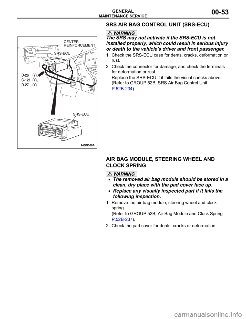
SRS AIR BAG CONTROL UNIT (SRS-ECU)
The SRS may not activate if the SRS-ECU is not
installed properly, which could result in serious injury
or death to the vehicle's driver and front passenger.
1. Check the SRS-ECU case for dents, cracks, deformation or
rust.
2. Check the connector for damage, and check the terminals
for deformation or rust.
Replace the SRS-ECU if it fails the visual checks above
(Refer to GROUP 52B, SRS Air Bag Control Unit
P.52B-234).
AIR BAG MODULE, STEERING WHEEL AND
CLOCK SPRING
The removed air bag module should be stored in a
clean, dry place with the pad cover face up.
Replace any visually inspected part if it fails the
following inspection.
1. Remove the air bag module, steering wheel and clock
spring.
(Refer to GROUP 52B, Air Bag Module and Clock Spring
P.52B-237).
2. Check the pad cover for dents, cracks or deformation.
Page 1276 of 1500

MAINTENANCE SERVICE
GENERAL00-55
The SRS may not activate if any of the above compo-
nents are not installed properly, which could result in
serious injury or death to the vehicle's driver and
front passenger.
11.Check the steering wheel for excessive free play.
Replace any part if it fails visual inspection (Refer to
GROUP 52B, Air Bag Module and Clock Spring P.52B-237).
FRONT SEATBACK ASSEMBLY WITH
SIDE-AIRBAG MODULE
If any improper part is found during the following
inspection, replace the front seatback assembly
with a new one.
Dispose of the old one according to the specified
procedure (Refer to GROUP 52B, Air Bag Module
Disposal Procedures P.52B-254).
Never attempt to measure the circuit resistance of
the air bag module (squib) even if you are using
the specified tester. If the circuit resistance is mea-
sured with a tester, accidental air bag deployment
will result in serious personal injury.
1. Check the air bag module deployment section for dents or
deformation.
2. Check the connector for damage; Check the terminals for
deformation; and check the harness for binding.
Replace the front seat if it fails the visual checks above
(Refer to GROUP 52A, Front Seat P.52A-33).
SEAT BELT WITH PRE-TENSIONER
If the seat belt pre-tensioner is not installed
securely and correctly, the seat belt pre-tensioner
may not operate normally.
If a dent, crack, deformation or rust is detected,
replace with a new seat belt pre-tensioner.
1. Check the seat belt pre-tensioner for dents or deformation.
2. Check that the seat belt pre-tensioner is installed correctly to
the vehicle body.
Replace the seat belt pre-tensioner if it fails the visual
checks above (Refer to GROUP 52B, Seat Belt
Pre-tensioner P.52B-250).
Page 1280 of 1500
13C-1
GROUP 13C
TRACTION
CONTROL SYSTEM
(TCL)
CONTENTS
GENERAL DESCRIPTION. . . . . . . . .13C-2
TRACTION CONTROL SYSTEM (TCL)
DIAGNOSIS . . . . . . . . . . . . . . . . . . . .13C-3
INTRODUCTION TO TRACTION CONTROL
SYSTEM (TCL) DIAGNOSIS . . . . . . . . . . . 13C-3
TROUBLESHOOTING STRATEGY . . . . . . 13C-3
DIAGNOSIS FUNCTION. . . . . . . . . . . . . . . 13C-3
DIAGNOSTIC TROUBLE CODE CHART . . 13C-8
DIAGNOSTIC TROUBLE CODE
PROCEDURES . . . . . . . . . . . . . . . . . . . . . . 13C-10
SYMPTOM CHART. . . . . . . . . . . . . . . . . . . 13C-23
SYMPTOM PROCEDURES . . . . . . . . . . . . 13C-23
DATA LIST REFERENCE TABLE . . . . . . . 13C-36
ACTUATOR TEST REFERENCE TABLE. . 13C-37
CHECK AT ABS/TCL-ECU RESISTANCE
AND TERMINAL VOLTAGE . . . . . . . . . . . . 13C-38RESISTANCE AND CONTINUITY
BETWEEN ABS-ECU AND WHEEL SPEED
SENSOR . . . . . . . . . . . . . . . . . . . . . . . . . . . 13C-39
VOLTAGE AND SIGNAL CHECK AT
ABS-ECU USING AN OSCILLOSCOPE . . . 13C-41
SPECIAL TOOLS . . . . . . . . . . . . . . . .13C-45
ON-VEHICLE SERVICE . . . . . . . . . . .13C-47
TCL INDICATOR LIGHT CHECK . . . . . . . . 13C-47
TCL OPERATION CHECK . . . . . . . . . . . . . 13C-47
TCL SWITCH CHECK . . . . . . . . . . . . . . . . . 13C-48
WHEEL SPEED SENSOR CHECK . . . . . . . 13C-48
TCL SWITCH . . . . . . . . . . . . . . . . . . .13C-49
REMOVAL AND INSTALLATION . . . . . . . . 13C-49
WHEEL SPEED SENSOR . . . . . . . . .13C-49
REMOVAL AND INSTALLATION . . . . . . . . 13C-49
ABS/TCL-ECU . . . . . . . . . . . . . . . . . .13C-49
REMOVAL AND INSTALLATION . . . . . . . . 13C-49
Page 1281 of 1500
GENERAL DESCRIPTION
TRACTION CONTROL SYSTEM (TCL)13C-2
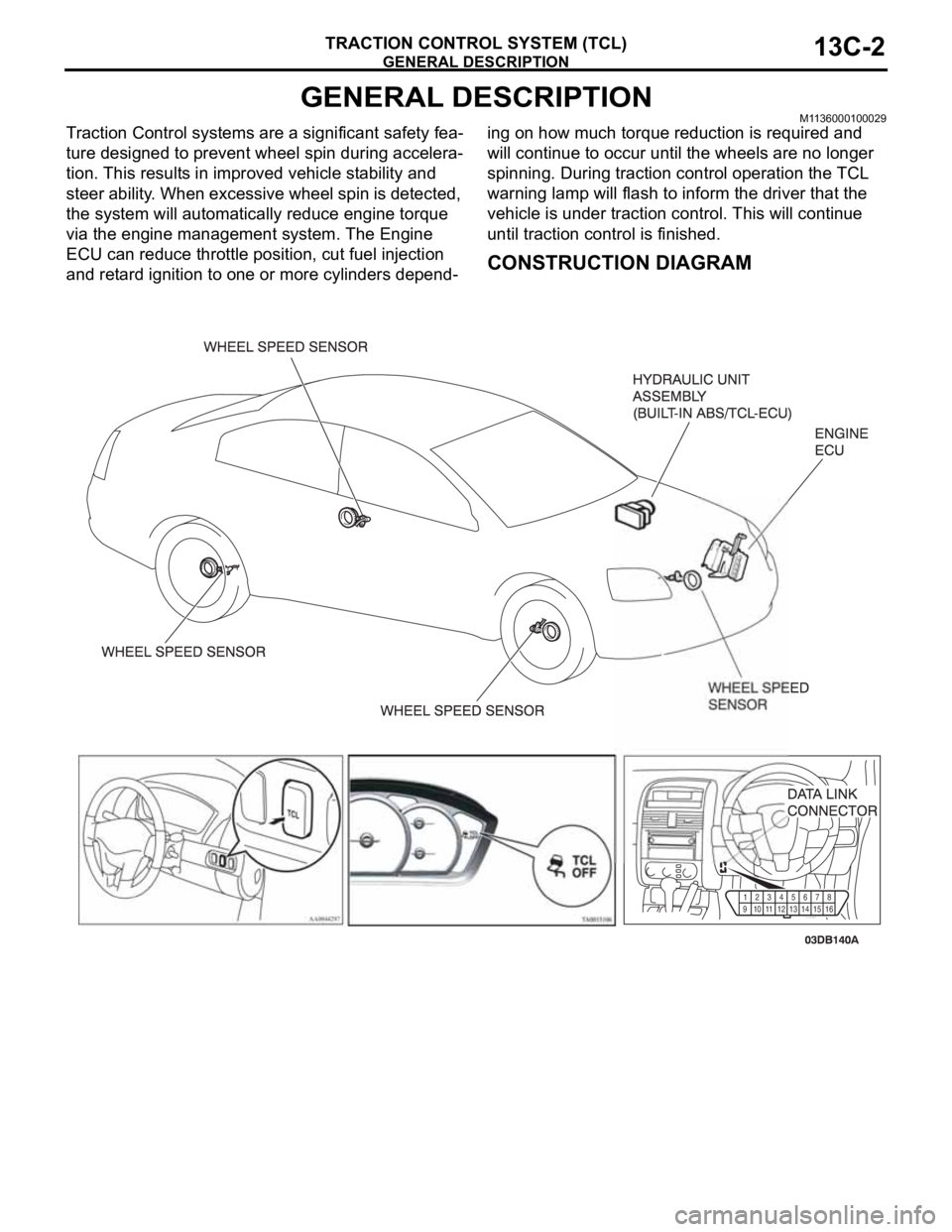
GENERAL DESCRIPTIONM1136000100029
Traction Control systems are a significant safety fea-
ture designed to prevent wheel spin during accelera-
tion. This results in improved vehicle stability and
steer ability. When excessive wheel spin is detected,
the system will automatically reduce engine torque
via the engine management system. The Engine
ECU can reduce throttle position, cut fuel injection
and retard ignition to one or more cylinders depend-ing on how much torque reduction is required and
will continue to occur until the wheels are no longer
spinning. During traction control operation the TCL
warning lamp will flash to inform the driver that the
vehicle is under traction control. This will continue
until traction control is finished.
CONSTRUCTION DIAGRAM
91011
1213141516 12345
678
Page 1282 of 1500
TRACTION CONTROL SYSTEM (TCL) DIAGNOSIS
TRACTION CONTROL SYSTEM (TCL)13C-3
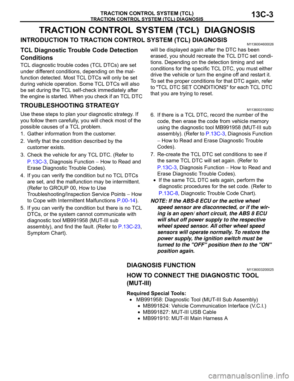
TRACTION CONTROL SYSTEM (TCL) DIAGNOSIS
INTRODUCTION TO TRACTION CONTROL SYSTEM (TCL) DIAGNOSISM1136004600026
TCL Diagnostic Trouble Code Detection
Conditions
TCL diagnostic trouble codes (TCL DTCs) are set
under different conditions, depending on the mal-
function detected. Most TCL DTCs will only be set
during vehicle operation. Some TCL DTCs will also
be set during the TCL self-check immediately after
the engine is started. When you check if an TCL DTC will be displayed again after the DTC has been
erased, you should recreate the TCL DTC set condi-
tions. Depending on the detection timing and set
conditions for the specific TCL DTC, you must either
drive the vehicle or turn the engine off and restart it.
To set the proper conditions for that DTC again, refer
to "TCL DTC SET CONDITIONS" for each TCL DTC
that you are trying to reset.
TROUBLESHOOTING STRATEGYM1136003100062
Use these steps to plan your diagnostic strategy. If
you follow them carefully, you will check most of the
possible causes of a TCL problem.
1. Gather information from the customer.
2. Verify that the condition described by the
customer exists.
3. Check the vehicle for any TCL DTC. (Refer to
P.13C-3, Diagnosis Function
How to Read and
Erase Diagnostic Trouble Codes).
4. If you can verify the condition but no TCL DTCs
are set, and the malfunction may be intermittent.
(Refer to GROUP 00, How to Use
Troubleshooting/Inspection Service Points
How
to Cope with Intermittent Malfunctions P.00-14).
5. If you can verify the condition but there is no TCL
DTCs, or the system cannot communicate with
diagnostic tool MB991958 (MUT-III sub
assembly), and find the fault. (Refer to P.13C-23,
Symptom Chart).6. If there is a TCL DTC, record the number of the
code, then erase the code from vehicle memory
using the diagnostic tool MB991958 (MUT-III sub
assembly). (Refer to P.13C-3, Diagnosis Function
How to Read and Erase Diagnostic Trouble
Codes).
7. Re-create the TCL DTC set conditions to see if
the same TCL DTC will set again. (Refer to
P.13C-3, Diagnosis Function
How to Read and
Erase Diagnostic Trouble Codes).
If the same TCL DTC sets again, perform the
diagnostic procedures for the set code. (Refer to
P.13C-8, Diagnostic Trouble Code Chart).
NOTE: If the ABS-8 ECU or the active wheel
speed sensor are disconnected, or if the wir-
ing is an open/ short circuit, the ABS 8 ECU
will shut off power supply to the respective
wheel speed sensor. All other wheel speed
sensors will operate normally. To restore the
power supply, the ignition switch must be
turned to the "OFF" position then to the "ON"
position again.
DIAGNOSIS FUNCTIONM1136003200025
HOW TO CONNECT THE DIAGNOSTIC TOOL
(MUT-III)
Required Special Tools:
MB991958: Diagnostic Tool (MUT-III Sub Assembly)
MB991824: Vehicle Communication Interface (V.C.I.)
MB991827: MUT-III USB Cable
MB991910: MUT-III Main Harness A
Page 1287 of 1500
TRACTION CONTROL SYSTEM (TCL) DIAGNOSIS
TRACTION CONTROL SYSTEM (TCL)13C-8
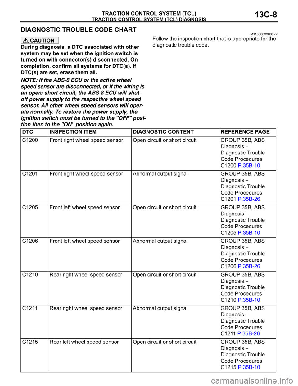
DIAGNOSTIC TROUBLE CODE CHARTM1136003300022
During diagnosis, a DTC associated with other
system may be set when the ignition switch is
turned on with connector(s) disconnected. On
completion, confirm all systems for DTC(s). If
DTC(s) are set, erase them all.
NOTE: If the ABS-8 ECU or the active wheel
speed sensor are disconnected, or if the wiring is
an open/ short circuit, the ABS 8 ECU will shut
off power supply to the respective wheel speed
sensor. All other wheel speed sensors will oper-
ate normally. To restore the power supply, the
ignition switch must be turned to the "OFF" posi-
tion then to the "ON" position again.Follow the inspection chart that is appropriate for the
diagnostic trouble code.
DTC INSPECTION ITEM DIAGNOSTIC CONTENT REFERENCE PAGE
C1200 Front right wheel speed sensor Open circuit or short circuit GROUP 35B, ABS
Diagnosis
Diagnostic Trouble
Code Procedures
C1200 P.35B-10
C1201 Front right wheel speed sensor Abnormal output signal GROUP 35B, ABS
Diagnosis
Diagnostic Trouble
Code Procedures
C1201 P.35B-26
C1205 Front left wheel speed sensor Open circuit or short circuitGROUP 35B, ABS
Diagnosis
Diagnostic Trouble
Code Procedures
C1205 P.35B-10
C1206 Front left wheel speed sensor Abnormal output signal GROUP 35B, ABS
Diagnosis
Diagnostic Trouble
Code Procedures
C1206 P.35B-26
C1210 Rear right wheel speed sensor Open circuit or short circuitGROUP 35B, ABS
Diagnosis
Diagnostic Trouble
Code Procedures
C1210 P.35B-10
C1211 Rear right wheel speed sensor Abnormal output signal GROUP 35B, ABS
Diagnosis
Diagnostic Trouble
Code Procedures
C1211 P.35B-26
C1215 Rear left wheel speed sensor Open circuit or short circuit GROUP 35B, ABS
Diagnosis
Diagnostic Trouble
Code Procedures
C1215 P.35B-10