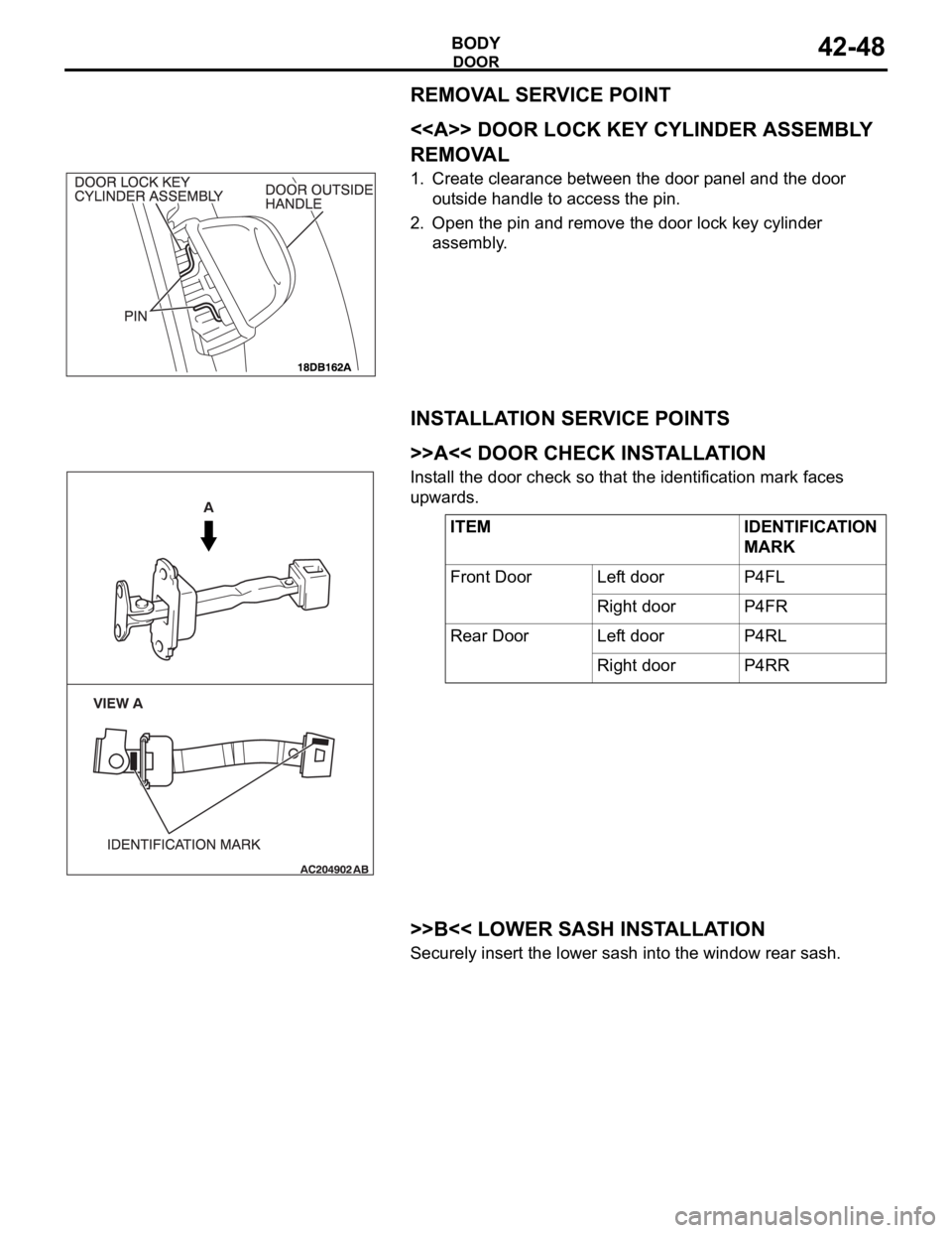
2005 MITSUBISHI 380 ECU
[x] Cancel search: ECUPage 1047 of 1500

WINDSHIELD WIPER AND WASHER
EXTERIOR51-14
WINDSHIELD WIPER AND WASHER
GENERAL DESCRIPTIONM1511000100558
WINDSHIELD WIPER AND WASHER
OPERATION
.
WINDSHIELD LOW-SPEED (AND
HIGH-SPEED) WIPER OPERATION
If the windshield low-speed wiper switch is turned
to the ON position with the ignition switch at the
"ACC" or "ON" position, the column switch sends
a low-speed wiper ON and high-speed wiper OFF
signals to the front-ECU. This turns the wiper sig-
nal on and the wiper speed control relay off
(low-speed), causing the wipers to operate at
low-speed.
If the windshield high-speed wiper switch is
turned to the ON position, the column switch
sends a low-speed wiper OFF and high-speed
wiper ON signals to the front-ECU. This turns
both the wiper signal and the wiper speed control
relay on (high-speed), causing the wipers to
operate at high-speed.
NOTE: The windshield wiper speed is adjustable
with the built-in wiper speed control relay.
High-speed operations take place when the wiper
speed control relay is set to "ON" and low-speed
operations take place when the wiper speed control
relay is set to "OFF".
.
WINDSHIELD INTERMITTENT WIPER
OPERATION
The ETACS-ECU calculates the wiper operation
interval according to the voltage signal sent from the
column switch. Then the ETACS-ECU sends a signal
to the front-ECU. The front-ECU determines the
wiper operation interval and turns on the wiper relay
signal relay. This causes the wiper auto stop relay to
turn on. Then the wiper auto stop relay will turn off
after the wipers reach the park position. This causes
the wiper signal relay and then the wipers to turn off.
If the wiper signal relay remains off for the wiper
operation interval, the relay turns on again, causing
the wipers to operate in intermittent mode.
.
WINDSHIELD MIST WIPER OPERATION
If the windshield mist wiper switch is turned to the
ON position with the ignition switch at the "ACC"
or "ON" position, the mist wiper high-speed oper-
ation signal is sent to the front-ECU. This signal
turns on the wiper speed control relay, causing
the wipers to work at high-speed while the mist
switch is on.
While the windshield mist wiper switch remains
turned on when the intermittent mode is still work-
ing, the wipers work as the mist wiper. However,
the wipers return to the intermittent mode again
when the switch is changed back to "INT" posi-
tion.
To prevent the windshield mist wiper from operat-
ing when the windshield wiper switch is turned
OFF, the windshield mist wiper does not work for
0.5 second after the windshield intermittent wiper
switch, the windshield low-speed wiper switch
and the windshield high-speed wiper switch are
turned OFF.
.
WINDSHIELD WASHER OPERATION
If the windshield washer switch is turned to the
ON position with the ignition switch at "ACC" or
"ON" position, the windshield washer ON signal is
sent to the front-ECU. After 0.3 second, the wind-
shield wiper signal turns on. After the windshield
washer switch signal turns off, the windshield
wiper signal turns off in three seconds.
If the windshield washer switch is turned on while
the windshield wiper is at intermittent mode, and
the windshield washer switch is turned OFF
within 0.2 second, the wiper works only once to
perform mist operation. When the windshield
washer switch is turned on for more than 0.2 sec-
ond, the wiper performs the same movement as
normal condition from the time when 0.2 second
has elapsed, and then returns to intermittent
operation.
WINDSHIELD WIPER AND WASHER DIAGNOSISM1511000700389
The windshield wiper and washer are controlled by
the Simplified Wiring System (SWS). For trouble-
shooting, refer to GROUP 54B, SWS Diagnosis
P.54B-10.NOTE: Even when the ETACS-ECU has failed, the
windshield wiper can work at low speed as fail-safe
mode. (Normally, the windshield wiper operates
when the ignition switch is at the "ACC" position. But,
if it enters the fail-safe mode, the wiper can operate
only when the ignition switch is at the "ON" position.)
Page 1079 of 1500

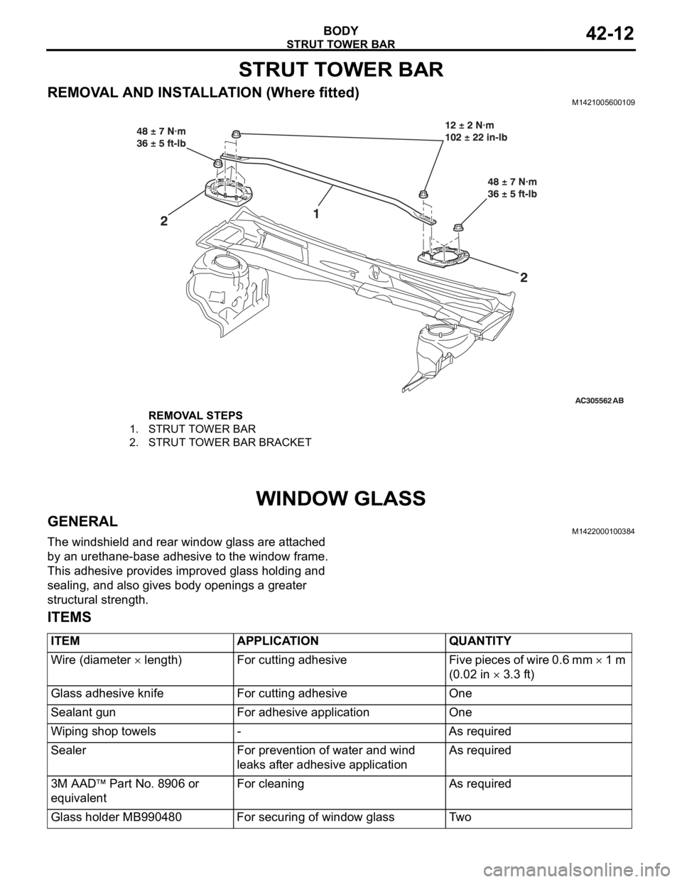
STRUT TOWER BAR
BODY42-12
STRUT TOWER BAR
REMOVAL AND INSTALLATION (Where fitted)M1421005600109
WINDOW GLASS
GENERALM1422000100384
The windshield and rear window glass are attached
by an urethane-base adhesive to the window frame.
This adhesive provides improved glass holding and
sealing, and also gives body openings a greater
structural strength.
ITEMS
REMOVAL STEPS
1. STRUT TOWER BAR
2. STRUT TOWER BAR BRACKET
ITEM APPLICATION QUANTITY
Wire (diameter
length) For cutting adhesive Five pieces of wire 0.6 mm 1 m
(0.02 in
3.3 ft)
Glass adhesive knife For cutting adhesive One
Sealant gun For adhesive application One
Wiping shop towels - As required
Sealer For prevention of water and wind
leaks after adhesive applicationAs required
3M AAD
Part No. 8906 or
equivalentFor cleaning As required
Glass holder MB990480 For securing of window glass Two
Page 1115 of 1500

Page 1134 of 1500

KEYLESS ENTRY SYSTEM
BODY42-67
KEYLESS ENTRY SYSTEM
GENERAL DESCRIPTIONBGBJABIE
Antenna and receiver are incorporated in the
ETACS-ECU.
ID code can be registered by using Diagnostic
tool (MUT-III).
Transmitter is a key holder type, which incorpo-
rates lock button, unlock button, trunk button and
panic button
When the transmitter unlock button is pressed
once, the driver's door will be unlocked. If the but-
ton is pressed twice, all the doors will be
unlocked. The adjustment function also allows
you to open all the doors by pressing the unlock
button only once. For further details on using the
multi-center display to adjust the unlock opera-
tion, refer to GROUP 54B, On-vehicle Service
P.54B-486.
When the transmitter is operated, the answer-
back function will work as follows:
The answerback operation can be altered as fol-
lows:NOTE: Enabling/disabling the hazard warning
light flashing, the horn sounding in accordance
with the answerback function. For further details
on using the transmitter to adjust answerback,
P.42-72 see the section below. For further details
on using the multi-center display to adjust
answerback, refer to GROUP 54B, On-vehicle
Service P.54B-486. ITEM OPERATION
DOORS LOCKED DOORS UNLOCKED
Dome light Flashes once Illuminates for 15 seconds
Turn-signal lights (RH and LH) Flashes once Flashes twice
Horn Sounds once when the lock button
is pressed with all the doors locked-
ITEM ADJUSTMENT ITEM ADJUSTMENT DETAIL
Keyless entry system
confirmation by turn
signal lightsAdjustment of hazard answerback
when the transmitter is used to
lock doorsWhen adjusting hazard answerback after the
doors are locked with the transmitter, the
following flashing conditions can be selected.
a. Flash (default)
b. No flash
Adjustment of hazard answerback
when the transmitter is used to
unlock doorsWhen adjusting hazard answerback after the
doors are unlocked with the transmitter, the
following flashing conditions can be selected.
a. Flash (default)
b. No flash
Keyless entry system
confirmation by hornAdjustment of horn answerback
when the transmitter is used to
lock doorsWhen adjusting horn answerback after the
doors are locked with the transmitter, the
following horn conditions can be selected.
a. Horn sounds
b. Horn sounds if doors are already locked
(default)
c. Horn does not sound
Page 1135 of 1500

KEYLESS ENTRY SYSTEM
BODY42-68
If none of the doors is opened or the ignition key
is not inserted in the ignition switch within 30 sec-
onds after the doors are unlocked using the
transmitter, the ETACS-ECU will relock the doors
automatically. This is called "Timer lock function."
This timer lock function prevents accidental
unlocking of doors. The adjustment function
allows you to change the timer lock period from 30 seconds (default setting) to 60, 120 or 180
seconds. For further details on using the
multi-center display (middle grade type) to adjust
the timer lock period, refer to GROUP 54B,
On-vehicle Service P.54B-486.
NOTE: The timer lock period begins when the doors
are unlocked, and ends when the doors is relocked
automatically.
KEYLESS ENTRY SYSTEM DIAGNOSISBGBCJGAI
The keyless entry system is controlled by the Simpli-
fied Wiring System (SWS). Refer to GROUP 54B,
SWS Diagnosis P.54B-57.
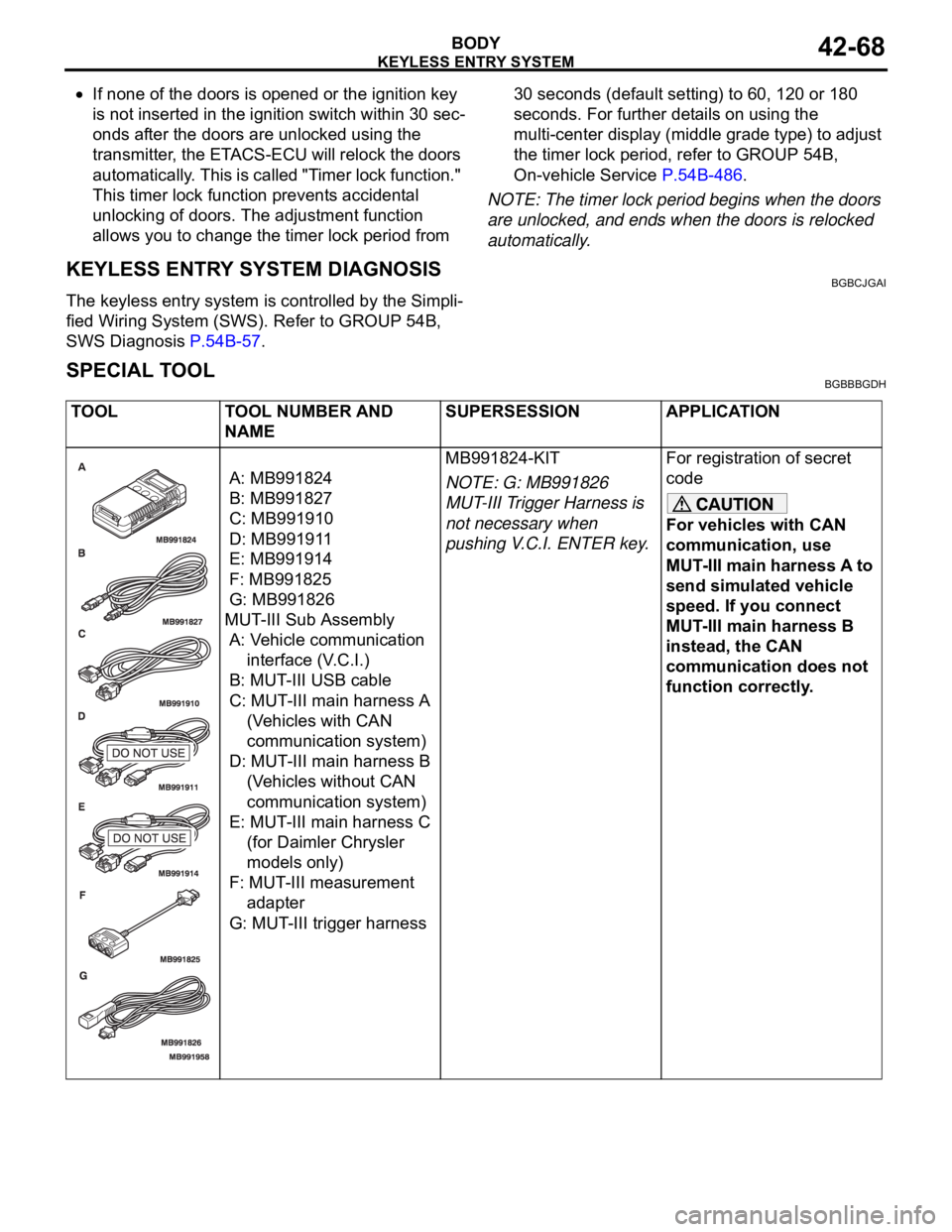
SPECIAL TOOLBGBBBGDH
TOOL TOOL NUMBER AND
NAMESUPERSESSION APPLICATION
A: MB991824
B: MB991827
C: MB991910
D: MB991911
E: MB991914
F: MB991825
G: MB991826
MUT-III Sub Assembly
A: Vehicle communication
interface (V.C.I.)
B: MUT-III USB cable
C: MUT-III main harness A
(Vehicles with CAN
communication system)
D: MUT-III main harness B
(Vehicles without CAN
communication system)
E: MUT-III main harness C
(for Daimler Chrysler
models only)
F: MUT-III measurement
adapter
G: MUT-III trigger harnessMB991824-KIT
NOTE: G: MB991826
MUT-III Trigger Harness is
not necessary when
pushing V.C.I. ENTER key.For registration of secret
code
For vehicles with CAN
communication, use
MUT-III main harness A to
send simulated vehicle
speed. If you connect
MUT-III main harness B
instead, the CAN
communication does not
function correctly.
Page 1139 of 1500

KEYLESS ENTRY SYSTEM
BODY42-72
NOTE: The adjustment function allows you to change the timer
lock period from 30 seconds (initial setting) to 60, 120 or 180
seconds. Prior to this inspection, confirm which setting is acti-
vated.
ENABLING/DISABLING THE ANSWERBACK
FUNCTION
BGBDGCGD
When the doors are locked or unlocked by using the transmit-
ter, the dome light will flash/illuminate, the turn-signal lights will
flash (hazard answerback), or the horn will sound (horn
answerback) to inform the driver.
The hazard answerback and horn answerback functions can be
enabled or disabled according to the following procedure:
ENABLING/DISABLING THE HAZARD
ANSWERBACK FUNCTION
.
How to adjust hazard answerback when the trans-
mitter is used to lock doors
1. Remove the ignition key.
2. Push the ”unlock” button and then push the ”lock“ button
within 4 seconds to 10 seconds.
3. Release the ”lock” button within 10 seconds after Step 2 and
then release the “unlock” button. The ETACS-ECU tone
alarm will sound, indicating that the hazard answerback
function can be enabled or disabled when the doors are
locked.
Enable the hazard answerback function when the
doors are locked: The ETACS-ECU tone alarm will
sound once.
Disable the hazard answerback function when the
doors are locked: The ETACS-ECU tone alarm will
sound twice.
.
How to adjust hazard answerback when the
transmitter is used to unlock doors
1. Remove the ignition key.
2. Push the ”unlock” button and then push the ”lock“ button
within 4 seconds to 10 seconds.
3. Release the ”lock” button within 10 seconds after Step 2 and
then release the “unlock” button. The ETACS-ECU tone
alarm will sound, indicating that the hazard answerback
function can be enabled or disabled when the door are
unlocked.
Enable the hazard answerback function when the
doors are unlocked: The ETACS-ECU tone alarm
will sound once.
Disable the hazard answerback function when the
doors are unlocked: The ETACS-ECU tone alarm
will sound twice.
Page 1140 of 1500

KEYLESS ENTRY SYSTEM
BODY42-73
ENABLING/DISABLING THE HORN
ANSWERBACK FUNCTION
.
1. Remove the ignition key.
2. Push the ”unlock” button and then push the ”lock“ button
within 4 seconds to 10 seconds.
3. Release the ”lock” button within 10 seconds after Step 2 and
then release the “unlock” button. The ETACS-ECU tone
alarm will sound, indicating that the horn answerback
function can be enabled or disabled.
Enable the horn answerback function*: The
ETACS-ECU tone alarm will sound once.
Disable the horn answerback function: The
ETACS-ECU tone alarm will sound twice.
Enable the horn answerback function**: The
ETACS-ECU tone alarm will sound three times.
NOTE: .
*: The horn will sound if "LOCK" button is pressed with the
doors locked.
**: The horn will sound if the doors are locked with the key-
less entry system.
HOW TO REGISTER SECRET CODEBGBHCCCB
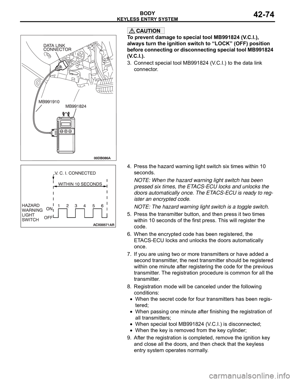
Required Special Tools:
: MUT-III Sub Assembly
MB991824: Vehicle Communication Interface (V.C.I.)
MB991910: MUT-III Main harness A
Each individual secret code is registered inside the transmitter,
and so it is necessary to resister these codes with the
EEPROM inside the receiver in the following cases.
When the transmitter or ETACS-ECU is replaced
If more transmitters are to be used
If it appears that a problem is occurring because of faulty
registration of a code.
A maximum of four different codes can be stored in the
EEPROM memory (four different transmitters can be used).
When the code for the first transmitter is registered, the previ-
ously registered codes for all transmitters are cleared. There-
fore, if you are using four transmitters or are adding more
transmitters, the codes for all transmitters must be registered at
the same time.
WHEN SPECIAL TOOL MB991824 (V.C.I.) IS USED
.
1. Check that the doors lock normally when the key is used.
2. Insert the ignition key.
Page 1141 of 1500

KEYLESS ENTRY SYSTEM
BODY42-74
To prevent damage to special tool MB991824 (V.C.I.),
always turn the ignition switch to “LOCK” (OFF) position
before connecting or disconnecting special tool MB991824
(V.C.I.).
3. Connect special tool MB991824 (V.C.I.) to the data link
connector.
4. Press the hazard warning light switch six times within 10
seconds.
NOTE: When the hazard warning light switch has been
pressed six times, the ETACS-ECU locks and unlocks the
doors automatically once. The ETACS-ECU is ready to reg-
ister an encrypted code.
NOTE: The hazard warning light switch is a toggle switch.
5. Press the transmitter button, and then press it two times
within 10 seconds of the first press. This will register the
code.
6. When the encrypted code has been registered, the
ETACS-ECU locks and unlocks the doors automatically
once.
7. If you are using two or more transmitters or have added a
second transmitter, the next transmitter should be registered
within one minute after registering the code for the previous
transmitter. The registration procedure is common for all the
transmitter.
8. Registration mode will be canceled under the following
conditions:
When the secret code for four transmitters has been regis-
tered;
When passing one minute after finishing the registration of
all transmitters;
When special tool MB991824 (V.C.I.) is disconnected;
When the key is removed from the key cylinder;
9. After the registration is completed, remove the ignition key
and close all the doors, and then check that the keyless
entry system operates normally.