Page 950 of 1500

THERMOSTAT
ENGINE COOLING14-35
THERMOSTAT
REMOVAL AND INSTALLATIONM1141002400475
Pre-removal and Post-installation Operation
Engine Coolant Draining and Refilling (Refer to 27).
Engine Cover Removal and Installation (Refer to GROUP
11C, Engine Assembly 11A-14).
Engine Control Unit (ECU) Removal and Installation
(Refer to GROUP 00, General 00-7).
Air Cleaner Removal and Installation (Refer to GROUP
15, Air Cleaner 4).
Strut Tower Bar Removal and Installation (Refer to
GROUP 42, Strut Tower Bar 12).
Battery and Battery Tray Removal and Installation
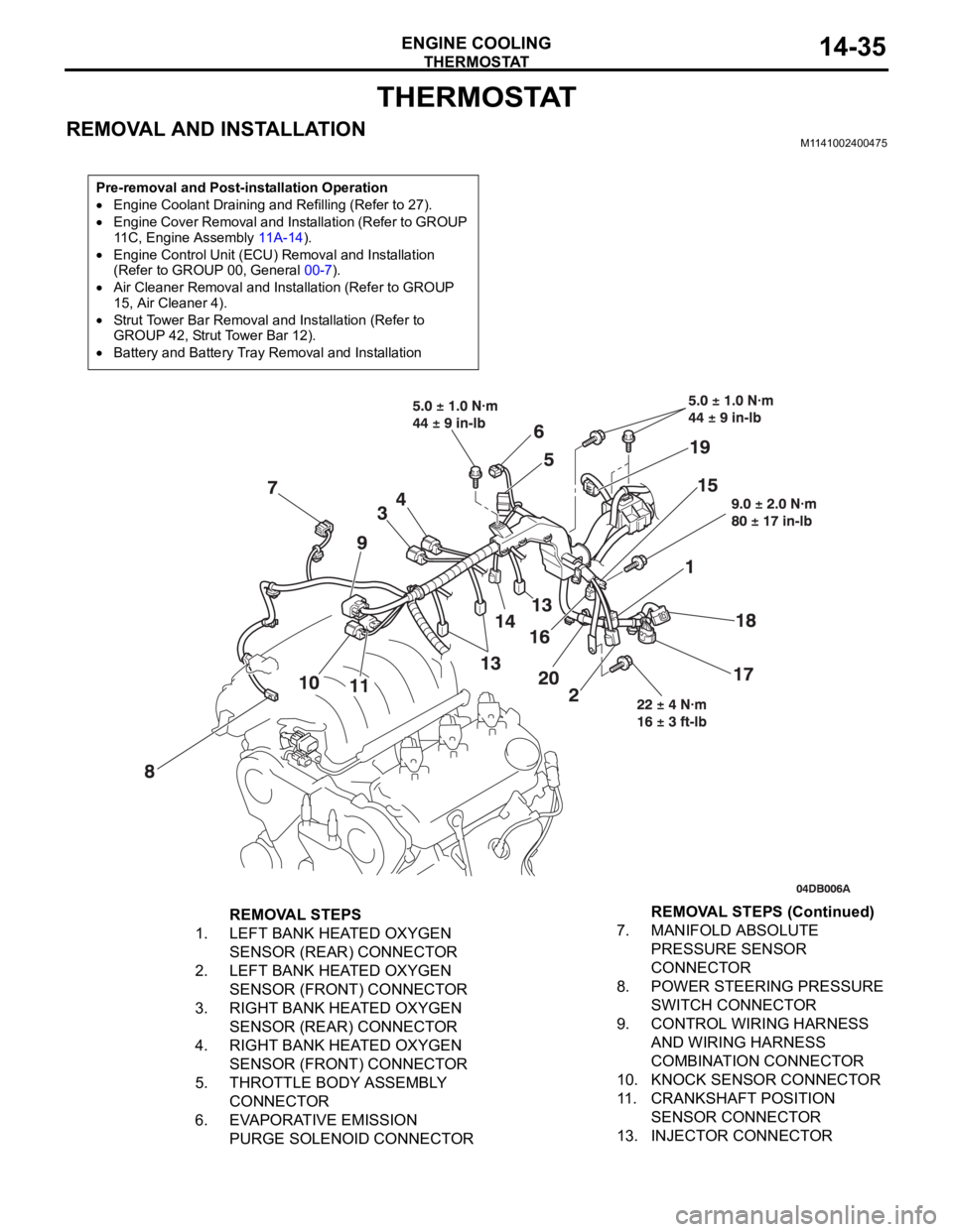
REMOVAL STEPS
1. LEFT BANK HEATED OXYGEN
SENSOR (REAR) CONNECTOR
2. LEFT BANK HEATED OXYGEN
SENSOR (FRONT) CONNECTOR
3. RIGHT BANK HEATED OXYGEN
SENSOR (REAR) CONNECTOR
4. RIGHT BANK HEATED OXYGEN
SENSOR (FRONT) CONNECTOR
5. THROTTLE BODY ASSEMBLY
CONNECTOR
6. EVAPORATIVE EMISSION
PURGE SOLENOID CONNECTOR7. MANIFOLD ABSOLUTE
PRESSURE SENSOR
CONNECTOR
8. POWER STEERING PRESSURE
SWITCH CONNECTOR
9. CONTROL WIRING HARNESS
AND WIRING HARNESS
COMBINATION CONNECTOR
10. KNOCK SENSOR CONNECTOR
11. CRANKSHAFT POSITION
SENSOR CONNECTOR
13. INJECTOR CONNECTORREMOVAL STEPS (Continued)
Page 963 of 1500
AIR CLEANER
INTAKE AND EXHAUST15-4
AIR CLEANER
REMOVAL AND INSTALLATIONM1151002100516
REMOVAL STEPS
1. AIR DUCT
2. AIRFLOW SENSOR CONNECTOR
3. AIRFLOW SENSOR
4. AIR CLEANER COVER
5. AIR CLEANER ELEMENT
6. BREATHER HOSE CONNECTION7. AIR INTAKE HOSE
ENGINE CONTROL UNIT (ECU) ).
8. AIR CLEANER BODY
9. AIR CLEANER BRACKET
UNDER COVER (LH)
10. AIRFLOW SENSOR NUTREMOVAL STEPS (Continued)
Page 987 of 1500

CHARGING SYSTEM
ENGINE ELECTRICAL16-10
REGULATED VOLTAGE TESTM1161001100666
Required Special Tools:
: Diagnostic Tool (MUT-III)
MB991824: V.C.I.
MB991827: MUT-III USB Cable
MB991910: MUT-III Main Harness A
MB998467: Alternator Harness Connector
This test determines whether the voltage regulator is
correctly controlling the alternator output voltage.
Battery posts, terminals and related acces-
sories contain lead and lead compounds.
WASH HANDS AFTER HANDLING.
1. Always be sure to check the following before the
test:
Alternator installation
Check to be sure that the battery installed in the
vehicle is fully charged. (Refer to GROUP 54A,
Chassis Electrical
Battery On-vehicle Service
Battery Check P.54A-5.)
Alternator drive belt tension (Refer to GROUP 00,
General
Maintenance Service Drive Belts
(For Alternator, Power Steering Pump and Air
Conditioning) (Check) P.00-39.)
Fusible link
Abnormal noise from the alternator while the
engine is running.2. Turn the ignition switch to the "LOCK" (OFF)
position.
3. Disconnect the negative battery cable.
4. Use the special tool (Alternator harness
connector: MB998467) to connect a digital-type
voltmeter between the alternator "S" terminal and
ground. (Connect the positive lead of the
voltmeter to the "S" terminal, and then connect the
negative lead of the voltmeter to a secure ground
or to the negative battery terminal.)
5. Connect a clamp-type DC test ammeter with a
range of 0
120 A to the alternator "B" terminal
output wire.
6. Reconnect the negative battery cable.
7. Connect an engine tachometer, or diagnostic tool.
8. Turn the ignition switch to the "ON" position and
check that the reading on the voltmeter is equal to
the battery positive voltage.
NOTE: If the voltage is 0 V, the cause is probably
an open circuit in the wire or fusible link between
the alternator "S" terminal and the battery positive
terminal or malfunctioning voltmeter.
9. Check to be sure that all lights and accessories
are off.
10.Start the engine.
Page 992 of 1500
Page 994 of 1500
CHARGING SYSTEM
ENGINE ELECTRICAL16-17
ASSEMBLY SERVICE POINTS
.
>>A<< REGULATOR ASSEMBLY INSTALLATION
After installing the regulator assembly, insert a wire through the
hole provided on the rear bracket while pressing down on the
brush, and secure the brush.
NOTE: By inserting a wire, the brush will be secured in place,
and the installation of the rotor will be easier.
.
>>B<< ROTOR ASSEMBLY INSTALLATION
After installing the rotor, remove the wire used to secure the
brush.
INSPECTIONM1161001700099.
ROTOR CHECK
1. Check the continuity between the slip rings of the field coil. If
the resistance value is not within the standard value, replace
the rotor.
Standard value: approximately 2
5
Page 1007 of 1500

IGNITION SYSTEM
ENGINE ELECTRICAL16-30
IGNITION SYSTEM
GENERAL DESCRIPTIONM1163000100528
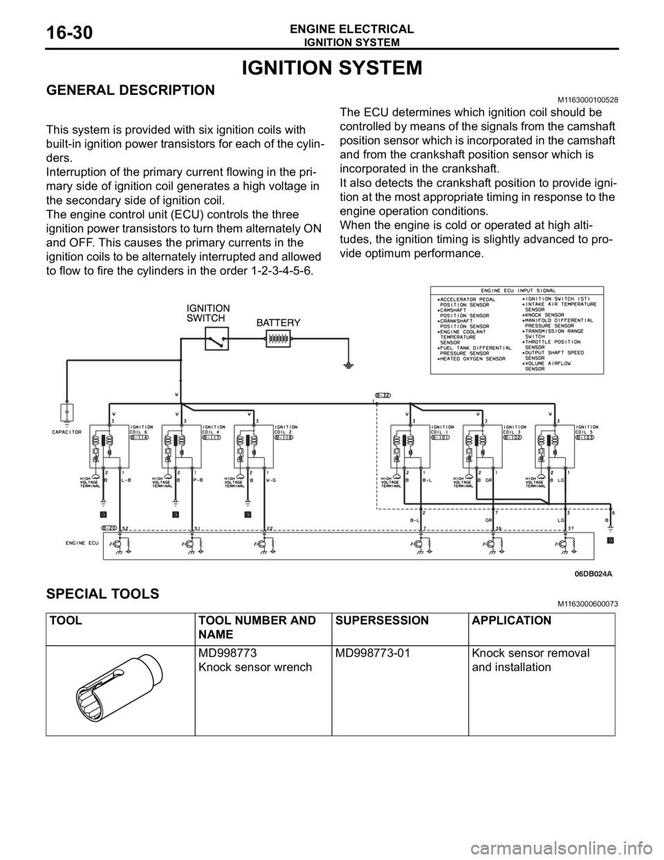
This system is provided with six ignition coils with
built-in ignition power transistors for each of the cylin-
ders.
Interruption of the primary current flowing in the pri-
mary side of ignition coil generates a high voltage in
the secondary side of ignition coil.
The engine control unit (ECU) controls the three
ignition power transistors to turn them alternately ON
and OFF. This causes the primary currents in the
ignition coils to be alternately interrupted and allowed
to flow to fire the cylinders in the order 1-2-3-4-5-6.The ECU determines which ignition coil should be
controlled by means of the signals from the camshaft
position sensor which is incorporated in the camshaft
and from the crankshaft position sensor which is
incorporated in the crankshaft.
It also detects the crankshaft position to provide igni-
tion at the most appropriate timing in response to the
engine operation conditions.
When the engine is cold or operated at high alti-
tudes, the ignition timing is slightly advanced to pro-
vide optimum performance.
SPECIAL TOOLSM1163000600073
TOOL TOOL NUMBER AND
NAMESUPERSESSION APPLICATION
MD998773
Knock sensor wrenchMD998773-01 Knock sensor removal
and installation
Page 1021 of 1500
ENGINE MOUNTING
POWER PLANT MOUNT32-4
ENGINE MOUNTING
REMOVAL AND INSTALLATIONM1321001100462
*: Indicates parts which should be initially tightened, and then fully tightened after placing the vehicle
horizontally and loading the full weight of the engine on the vehicle body.
Pre-removal Operation
Raise the engine and transaxle assembly until its weight is
not applied to the insulator, and support it securely.
REMOVAL STEPS
2. ENGINE MOUNTING STAY
3. MOUNTING BOLT
4. SELF LOCKING NUTS5. ENGINE MOUNT BRACKET
6. ENGINE MOUNT STOPPER
7. DYNAMIC DAMPERREMOVAL STEPS (Continued)
Page 1022 of 1500

TRANSAXLE MOUNTING
POWER PLANT MOUNT32-5
TRANSAXLE MOUNTING
REMOVAL AND INSTALLATIONM1321001400452
*: Indicates parts which should be initially tightened, and then fully tightened after placing the vehicle
horizontally and loading the full weight of the engine on the vehicle body.
Pre-removal Operation
Engine Control Unit (ECU) , Refer to GROUP 13B,
Engine Control Unit (ECU) 13A-675).
Air Cleaner Removal (Refer to GROUP 15, Air Cleaner
P.15-4).
Battery and Battery Tray Removal
Centremember Removal (Refer to P.32-7).
Engine Rear Roll Stopper Bracket Removal (Refer to
P.32-7).
Raise the engine and transaxle assembly until its weight
is not applied to the insulator, and support it securely.Post-installation Operation
Engine Rear Roll Stopper Bracket Installation (Refer to
P.32-7).
Centremember Installation (Refer to P.32-7).
Battery and Battery Tray Installation
Air Cleaner Installation (Refer to GROUP 15, Air Cleaner
P.15-4).
Engine Control Unit (ECU) Installation, Refer to GROUP
13B, Engine Control Unit (ECU) 13A-675).
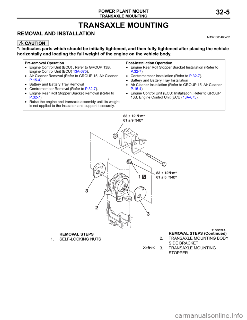
REMOVAL STEPS
1. SELF-LOCKING NUTS2. TRANSAXLE MOUNTING BODY
SIDE BRACKET
>>A<<3. TRANSAXLE MOUNTING
STOPPER REMOVAL STEPS (Continued)