2005 MITSUBISHI 380 ECU
[x] Cancel search: ECUPage 1232 of 1500
HOW TO USE TROUBLESHOOTING/INSPECTION SERVICE POINTS
GENERAL00-11
MEASURES TO TAKE AFTER
REPLACING THE ECU
If the trouble symptoms have not disappeared even
after replacing the ECU, repeat the inspection proce-
dure from the beginning.
CONNECTOR MEASUREMENT SERVICE POINTSM1001013600063
Turn the ignition switch to the "LOCK" (OFF) position when
connecting and disconnecting the connectors. Turn the ignition
switch to "ON" when measuring, unless there are instructions
to the contrary.
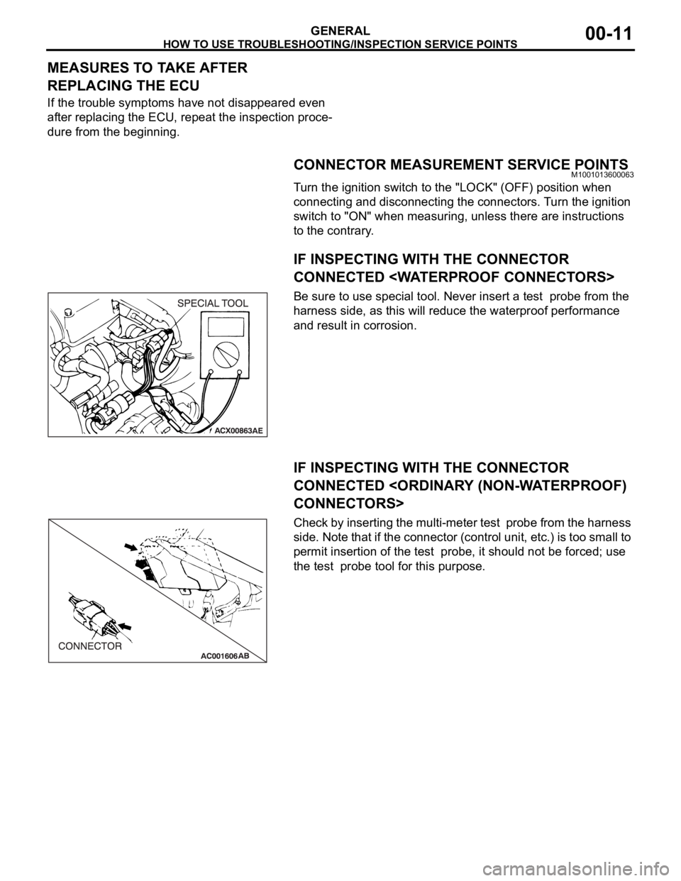
IF INSPECTING WITH THE CONNECTOR
CONNECTED
Be sure to use special tool. Never insert a test probe from the
harness side, as this will reduce the waterproof performance
and result in corrosion.
IF INSPECTING WITH THE CONNECTOR
CONNECTED
Check by inserting the multi-meter test probe from the harness
side. Note that if the connector (control unit, etc.) is too small to
permit insertion of the test probe, it should not be forced; use
the test probe tool for this purpose.
Page 1233 of 1500
HOW TO USE TROUBLESHOOTING/INSPECTION SERVICE POINTS
GENERAL00-12
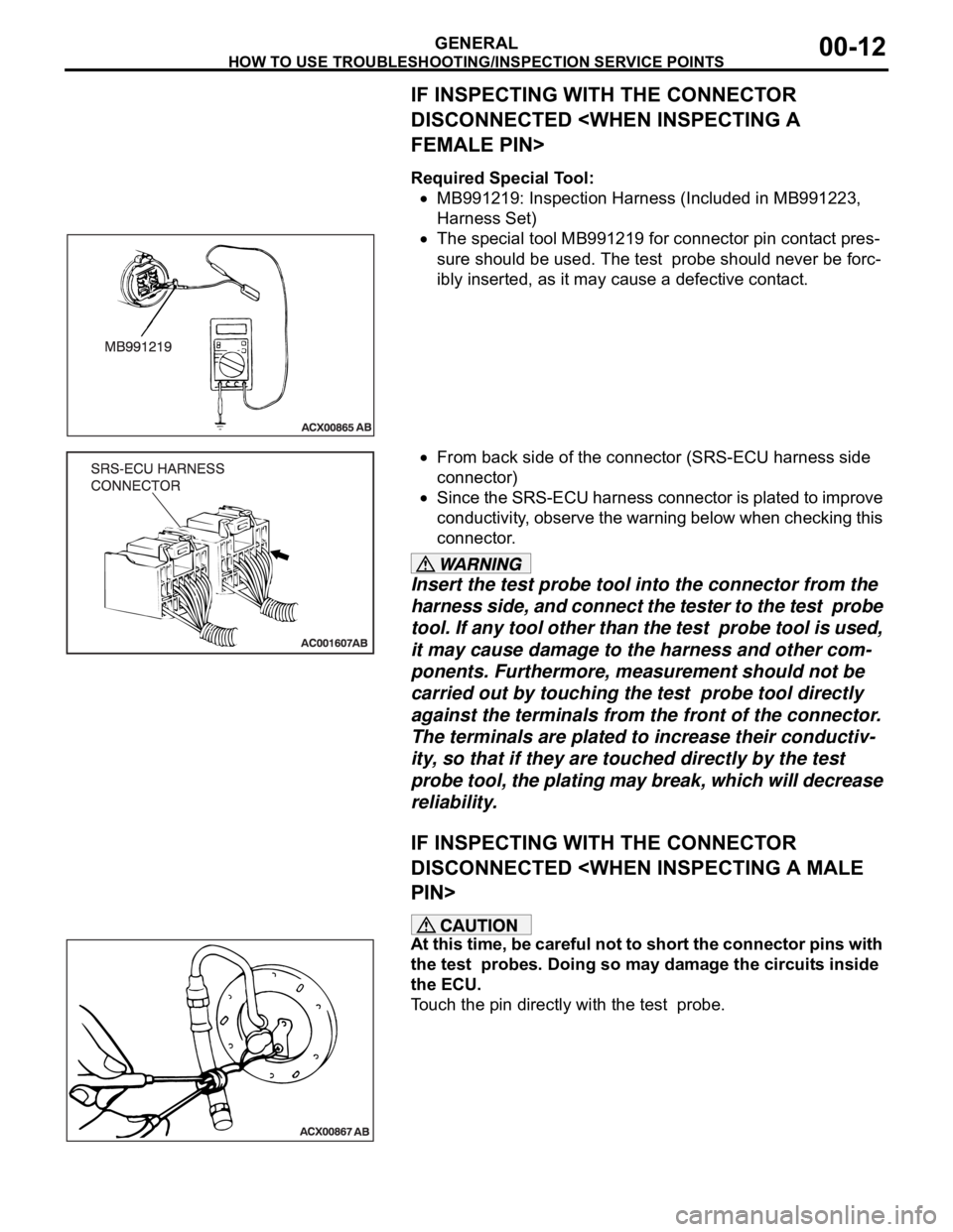
IF INSPECTING WITH THE CONNECTOR
DISCONNECTED
Required Special Tool:
MB991219: Inspection Harness (Included in MB991223,
Harness Set)
The special tool MB991219 for connector pin contact pres-
sure should be used. The test probe should never be forc-
ibly inserted, as it may cause a defective contact.
From back side of the connector (SRS-ECU harness side
connector)
Since the SRS-ECU harness connector is plated to improve
conductivity, observe the warning below when checking this
connector.
Insert the test probe tool into the connector from the
harness side, and connect the tester to the test probe
tool. If any tool other than the test probe tool is used,
it may cause damage to the harness and other com-
ponents. Furthermore, measurement should not be
carried out by touching the test probe tool directly
against the terminals from the front of the connector.
The terminals are plated to increase their conductiv-
ity, so that if they are touched directly by the test
probe tool, the plating may break, which will decrease
reliability.
IF INSPECTING WITH THE CONNECTOR
DISCONNECTED
At this time, be careful not to short the connector pins with
the test probes. Doing so may damage the circuits inside
the ECU.
Touch the pin directly with the test probe.
Page 1238 of 1500

AFFILIATED DTC REFERENCE TABLE
GENERAL00-17
AFFILIATED DTC REFERENCE TABLEM1001013000027
For vehicles with CAN, when DTC which influences
the transmission data is set to the ECU which sends
the data, DTC also could be set to the ECU which
receives and controls the transmission data. The
table below shows the relativity of DTC between
ECUs.
AFFILIATED
DTC’s RESULTS
P0513 P2138 TBA U1120 U1100 U1110
U1120 X - X - - -
U1100 - - - - - -
U1120 X X X X - X
U1110 - - - - - -
TBA - - - - - -
Page 1243 of 1500
PRECAUTIONS BEFORE SERVICE
GENERAL00-22
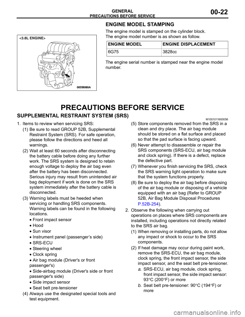
ENGINE MODEL STAMPING
The engine model is stamped on the cylinder block.
The engine model number is as shown as follow.
The engine serial number is stamped near the engine model
number.
PRECAUTIONS BEFORE SERVICE
SUPPLEMENTAL RESTRAINT SYSTEM (SRS)M1001011600056
1. Items to review when servicing SRS:
(1) Be sure to read GROUP 52B, Supplemental
Restraint System (SRS). For safe operation,
please follow the directions and heed all
warnings.
(2) Wait at least 60 seconds after disconnecting
the battery cable before doing any further
work. The SRS system is designed to retain
enough voltage to deploy the air bag even
after the battery has been disconnected.
Serious injury may result from unintended air
bag deployment if work is done on the SRS
system immediately after the battery cable is
disconnected.
(3) Warning labels must be heeded when
servicing or handling SRS components.
Warning labels can be found in the following
locations.
Front impact sensor
Hood
Sun visor
Instrument panel (passenger ’s side)
SRS-ECU
Steering wheel
Clock spring
Air bag module (Driver's or front
passenger's)
Side-airbag module (Driver's side or front
passenger's side)
Side impact sensor
Seat belt pre-tensioner
(4) Always use the designated special tools and
test equipment.(5) Store components removed from the SRS in a
clean and dry place. The air bag module
should be stored on a flat surface and placed
so that the pad surface is facing upward.
(6) Never attempt to disassemble or repair the
SRS components (SRS-ECU, air bag module
and clock spring). If there is a defect, replace
the defective part.
(7) Whenever you finish servicing the SRS, check
the SRS warning light operation to make sure
that the system functions properly.
(8) Be sure to deploy the air bag before disposing
of the air bag module or disposing of a vehicle
equipped with an air bag (Refer to GROUP
52B, Air Bag Module Disposal Procedures
P.52B-254).
2. Observe the following when carrying out
operations on places where SRS components are
installed, including operations not directly related
to the SRS air bag.
(1) When removing or installing parts, do not allow
any impact or shock to occur to the SRS
components.
(2) If heat damage may occur during paint work,
remove the SRS-ECU, the air bag module,
clock spring, the front impact sensor, the side
impact sensor, and the seat belt pre-tensioner.
a.SRS-ECU, air bag module, clock spring,
front impact sensor, the side impact sensor:
93
C (200F) or more
b.Seat belt pre-tensioner: 90
C (194F) or
more ENGINE MODEL ENGINE DISPLACEMENT
6G75 3828cc
Page 1244 of 1500
PRECAUTIONS BEFORE SERVICE
GENERAL00-23
HOW TO PERFORM VEHICLE IDENTIFICATION
NUMBER (VIN) WRITING
M1001011400063
The Vehicle Identification Number (VIN) is stored in the ECU by
the vehicle manufacture. If the VIN to be stored in the ECU is
eliminated fraudulently, the Malfunction Indicator Lamp (Check
Engine Lamp) illuminates and Diagnostic Trouble Code (DTC)
No.P0630 (VIN malfunction) is shown. When the ECU is
replaced, and entry of the VIN necessary due to DTC No.
P0630 (VIN malfunction). Enter the VIN in accordance with the
procedure as follows:
.
WRITING PROCEDURE
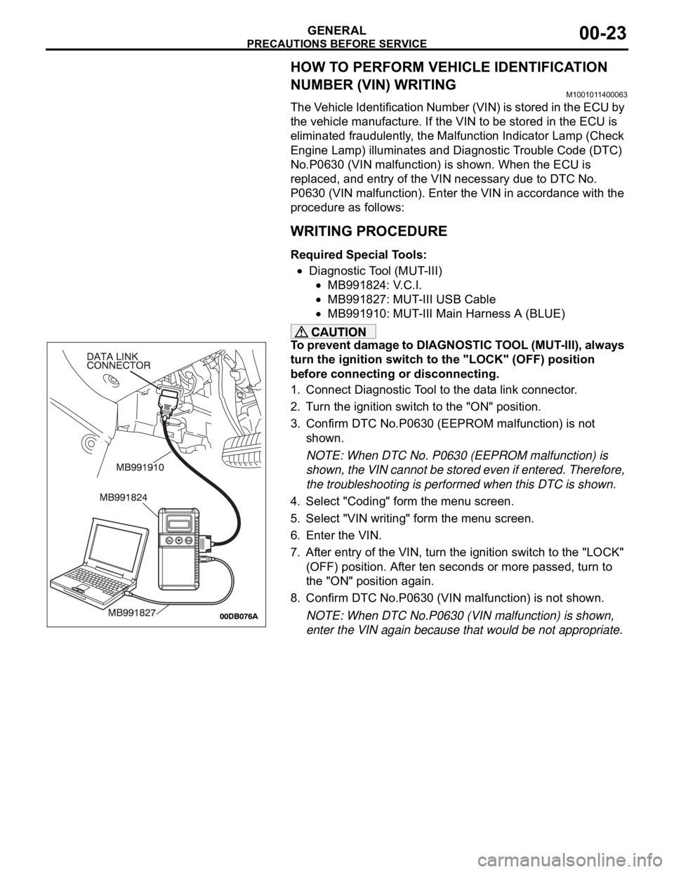
Required Special Tools:
Diagnostic Tool (MUT-III)
MB991824: V.C.I.
MB991827: MUT-III USB Cable
MB991910: MUT-III Main Harness A (BLUE)
To prevent damage to DIAGNOSTIC TOOL (MUT-III), always
turn the ignition switch to the "LOCK" (OFF) position
before connecting or disconnecting.
1. Connect Diagnostic Tool to the data link connector.
2. Turn the ignition switch to the "ON" position.
3. Confirm DTC No.P0630 (EEPROM malfunction) is not
shown.
NOTE: When DTC No. P0630 (EEPROM malfunction) is
shown, the VIN cannot be stored even if entered. Therefore,
the troubleshooting is performed when this DTC is shown.
4. Select "Coding" form the menu screen.
5. Select "VIN writing" form the menu screen.
6. Enter the VIN.
7. After entry of the VIN, turn the ignition switch to the "LOCK"
(OFF) position. After ten seconds or more passed, turn to
the "ON" position again.
8. Confirm DTC No.P0630 (VIN malfunction) is not shown.
NOTE: When DTC No.P0630 (VIN malfunction) is shown,
enter the VIN again because that would be not appropriate.
Page 1248 of 1500
TOWING AND HOISTING
GENERAL00-27
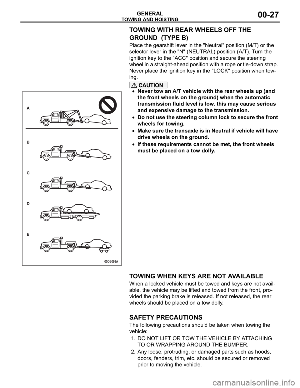
TOWING WITH REAR WHEELS OFF THE
GROUND (TYPE B)
Place the gearshift lever in the "Neutral" position (M/T) or the
selector lever in the "N" (NEUTRAL) position (A/T). Turn the
ignition key to the "ACC" position and secure the steering
wheel in a straight-ahead position with a rope or tie-down strap.
Never place the ignition key in the "LOCK" position when tow-
ing.
Never tow an A/T vehicle with the rear wheels up (and
the front wheels on the ground) when the automatic
transmission fluid level is low. this may cause serious
and expensive damage to the transmission.
Do not use the steering column lock to secure the front
wheels for towing.
Make sure the transaxle is in Neutral if vehicle will have
drive wheels on the ground.
If these requirements cannot be met, the front wheels
must be placed on a tow dolly.
.
TOWING WHEN KEYS ARE NOT AVAILABLE
When a locked vehicle must be towed and keys are not avail-
able, the vehicle may be lifted and towed from the front, pro-
vided the parking brake is released. If not released, the rear
wheels should be placed on a tow dolly.
.
SAFETY PRECAUTIONS
The following precautions should be taken when towing the
vehicle:
1. DO NOT LIFT OR TOW THE VEHICLE BY ATTACHING
TO OR WRAPPING AROUND THE BUMPER.
2. Any loose, protruding, or damaged parts such as hoods,
doors, fenders, trim, etc. should be secured or removed
prior to moving the vehicle.
Page 1268 of 1500
MAINTENANCE SERVICE
GENERAL00-47
6. Securely insert the dipstick.
NOTE: The transmission fluid should always be replaced
under the following conditions:
.
When troubleshooting the transaxle.
When overhauling the transaxle.
When the transmission fluid is noticeably dirty or burnt
(driving under severe conditions).
TRANSMISSION FLUID CHANGE
Refer to GROUP 23A, Automatic Transmission - On-vehicle
Service P.23A-296.
12. ENGINE COOLANT (CHANGE)M1001003100357
Check the cooling system parts such as the radiator, heater
and oil cooler hoses, thermostat and their connections for leak-
age and damage.
.
CHANGING COOLANT
1. Set the temperature control knob to the "HOT" position.
2. Run the engine until the engine coolant warms, and then
stop the engine.
When removing the radiator cap, use care to avoid
contact with hot coolant or steam. Place a shop towel
over the cap and turn the cap counterclockwise a lit-
tle to let the pressure escape through the vinyl tube.
After relieving the steam pressure, remove the cap by
slowly turning it counterclockwise.
3. Drain the water from the radiator, heater core and engine
after unplugging the radiator drain plug and removing the
radiator cap.
Page 1269 of 1500
MAINTENANCE SERVICE
GENERAL00-48
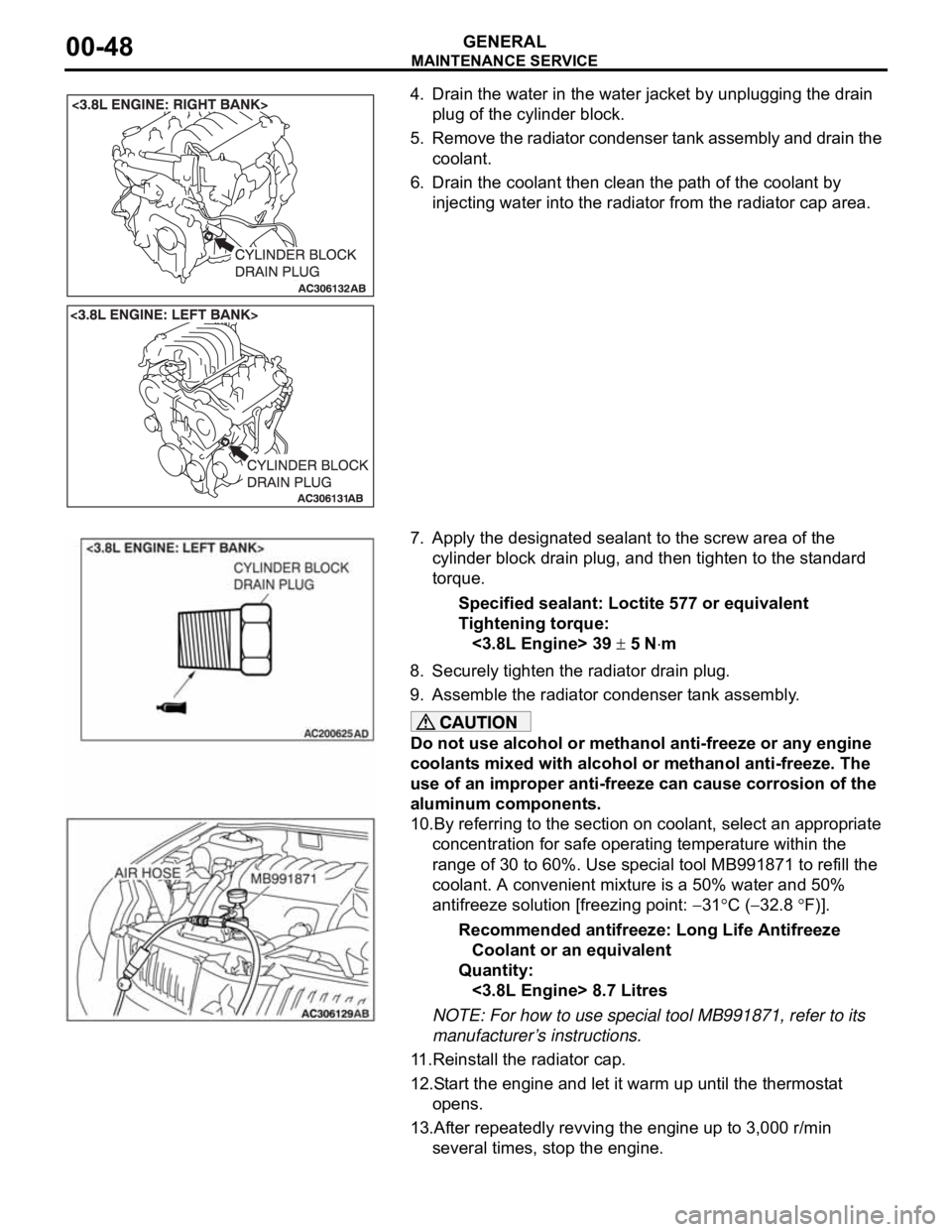
4. Drain the water in the water jacket by unplugging the drain
plug of the cylinder block.
5. Remove the radiator condenser tank assembly and drain the
coolant.
6. Drain the coolant then clean the path of the coolant by
injecting water into the radiator from the radiator cap area.
7. Apply the designated sealant to the screw area of the
cylinder block drain plug, and then tighten to the standard
torque.
Specified sealant: Loctite 577 or equivalent
Tightening torque:
<3.8L Engine> 39
5 Nm
8. Securely tighten the radiator drain plug.
9. Assemble the radiator condenser tank assembly.
Do not use alcohol or methanol anti-freeze or any engine
coolants mixed with alcohol or methanol anti-freeze. The
use of an improper anti-freeze can cause corrosion of the
aluminum components.
10.By referring to the section on coolant, select an appropriate
concentration for safe operating temperature within the
range of 30 to 60%. Use special tool MB991871 to refill the
coolant. A convenient mixture is a 50% water and 50%
antifreeze solution [freezing point:
31C (32.8 F)].
Recommended antifreeze: Long Life Antifreeze
Coolant or an equivalent
Quantity:
<3.8L Engine> 8.7 Litres
NOTE: For how to use special tool MB991871, refer to its
manufacturer’s instructions.
11.Reinstall the radiator cap.
12.Start the engine and let it warm up until the thermostat
opens.
13.After repeatedly revving the engine up to 3,000 r/min
several times, stop the engine.