2005 MERCEDES-BENZ SPRINTER heating
[x] Cancel search: heatingPage 1146 of 1232
OPERATION
The evaporator temperature sensor monitors the
temperature of the evaporator. The sensor will
change its internal resistance in response to the tem-
peratures it monitors. The ATC control module is
connected to the sensor through a sensor ground cir-
cuit and a sensor signal circuit. As the evaporator
temperature increases, the resistance of the sensor
decreases and the voltage monitored by the module
decreases. The module uses this monitored voltage
reading to an indication of the evaporator tempera-
ture. The ATC control module is programmed to
respond to this input by cycling the air conditioning
compressor clutch as necessary to optimize air condi-
tioning system performance and to protect the sys-
tem from evaporator freezing. The external location
of the sensor allows the sensor to be removed or
installed without disturbing the refrigerant in the
system. The evaporator temperature sensor is diag-
nosed by performing the ATC Function Test using a
DRBIIItscan tool. Refer to Body Diagnostic Proce-
dures.
REMOVAL
(1) Disconnect and isolate the battery negative
cable.
(2) Remove the radio (Refer to 8 - ELECTRICAL/
AUDIO/RADIO - REMOVAL).
(3) Remove glove compartment.
(4) Remove cover from instrument cluster (Refer to
23 - BODY/INSTRUMENT PANEL/INSTRUMENT
PANEL TOP COVER - REMOVAL).
(5) Remove the instrument cluster (Refer to 8 -
ELECTRICAL/INSTRUMENT CLUSTER - REMOV-
AL).
(6) Remove passenger side airbag.
(7) Remove cover above air nozzle on passenger
side.
(8) Remove speaker.
(9) Remove center section of instrument panel.
(10) Remove heater-A/C control from the instru-
ment panel (Refer to 24 - HEATING & AIR CONDI-
TIONING/CONTROLS/A/C HEATER CONTROL -
REMOVAL).
(11) Remove instrument panel top section.
(12) Remove electrical connections.
(13) Remove air bezels from instrument panel.
(14) Disconnect the wire harness connector from
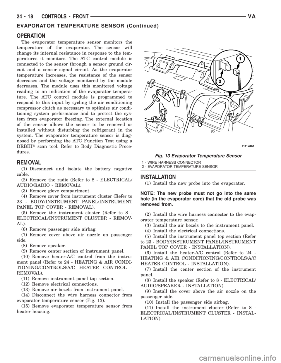
evaporator temperature sensor (Fig. 13).
(15) Remove evaporator temperature sensor from
heater housing.
INSTALLATION
(1) Install the new probe into the evaporator.
NOTE: The new probe must not go into the same
hole (in the evaporator core) that the old probe was
removed from.
(2) Install the wire harness connector to the evap-
orator temperature sensor.
(3) Install the air bezels to the instrument panel.
(4) Install the electrical connections.
(5) Install the instrument panel top section (Refer
to 23 - BODY/INSTRUMENT PANEL/INSTRUMENT
PANEL TOP COVER - INSTALLATION).
(6) Install the heater-A/C control (Refer to 24 -
HEATING & AIR CONDITIONING/CONTROLS/A/C
HEATER CONTROL - INSTALLATION).
(7) Install the center section of the instrument
panel.
(8) Install the speaker (Refer to 8 - ELECTRICAL/
AUDIO/SPEAKER - INSTALLATION).
(9) Install the cover above the air nozzle on the
passenger side.
(10) Install the passenger side airbag.
(11) Install the instrument cluster (Refer to 8 -
ELECTRICAL/INSTRUMENT CLUSTER - INSTAL-
LATION).
Fig. 13 Evaporator Temperature Sensor
1 - WIRE HARNESS CONNECTOR
2 - EVAPORATOR TEMPERATURE SENSOR
24 - 18 CONTROLS - FRONTVA
EVAPORATOR TEMPERATURE SENSOR (Continued)
Page 1147 of 1232
(12) Install the cover to the instrument cluster.
(13) Install glove compartment.
(14) Install the radio (Refer to 8 - ELECTRICAL/
AUDIO/RADIO - INSTALLATION).
(15) Reconnect the battery negative cable.
IN-CAR TEMPERATURE
SENSOR
DESCRIPTION
The in-car temperature sensor measures the actual
air temperature within the passenger compartment.
The in-car temperature sensor is located inside of the
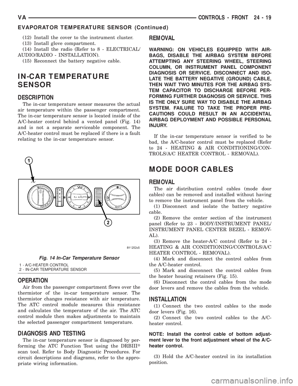
A/C-heater control behind a vented panel (Fig. 14)
and is not a separate serviceable component. The
A/C-heater control must be replaced if there is a fault
relating to the in-car temperature sensor.
OPERATION
Air from the passenger compartment flows over the
thermistor of the in-car temperature sensor. The
thermistor changes resistance with air temperature.
The ATC control module measures this resistance
and calculates the temperature of the air. The ATC
control module then makes adjustments to maintain
the selected passenger compartment temperature.
DIAGNOSIS AND TESTING
The in-car temperature sensor is diagnosed by per-
forming the ATC Function Test using the DRBIIIt
scan tool. Refer to Body Diagnostic Procedures. For
circuit descriptions and diagrams, refer to the appro-
priate wiring information.
REMOVAL
WARNING: ON VEHICLES EQUIPPED WITH AIR-
BAGS, DISABLE THE AIRBAG SYSTEM BEFORE
ATTEMPTING ANY STEERING WHEEL, STEERING
COLUMN, OR INSTRUMENT PANEL COMPONENT
DIAGNOSIS OR SERVICE. DISCONNECT AND ISO-
LATE THE BATTERY NEGATIVE (GROUND) CABLE,
THEN WAIT TWO MINUTES FOR THE AIRBAG SYS-
TEM CAPACITOR TO DISCHARGE BEFORE PER-
FORMING FURTHER DIAGNOSIS OR SERVICE. THIS
IS THE ONLY SURE WAY TO DISABLE THE AIRBAG
SYSTEM. FAILURE TO TAKE THE PROPER PRE-
CAUTIONS COULD RESULT IN AN ACCIDENTAL
AIRBAG DEPLOYMENT AND POSSIBLE PERSONAL
INJURY.
If the in-car temperature sensor is verified to be
bad, the A/C-heater control must be replaced (Refer
to 24 - HEATING & AIR CONDITIONING/CON-
TROLS/A/C HEATER CONTROL - REMOVAL).
MODE DOOR CABLES
REMOVAL
The air distribution control cables (mode door
cables) can be removed and installed without having
to remove the instrument panel from the vehicle.
(1) Disconnect and isolate the battery negative
cable.
(2) Remove the center section of the instrument
panel (Refer to 23 - BODY/INSTRUMENT PANEL/
INSTRUMENT PANEL CENTER BEZEL - REMOV-
AL).
(3) Remove the heater-A/C control (Refer to 24 -
HEATING & AIR CONDITIONING/CONTROLS/A/C
HEATER CONTROL - REMOVAL).
(4) Mark and disconnect the control cables from
the A/C-heater control.
(5) Mark and disconnect the control cables from
the heater housing retainers (Fig. 15).
(6) Disconnect the control cables from the mode
door levers and remove the cables from the vehicle.
INSTALLATION
(1) Connect the two control cables to the mode
door levers (Fig. 16).
(2) Connect the two control cables to the A/C-
heater control.
NOTE: Install the control cable of bottom adjust-
ment lever to the front adjustment wheel of the A/C-
heater control.
(3) Hold the A/C-heater control in its installation
position.
Fig. 14 In-Car Temperature Sensor
1 - A/C-HEATER CONTROL
2 - IN-CAR TEMPERATURE SENSOR
VACONTROLS - FRONT 24 - 19
EVAPORATOR TEMPERATURE SENSOR (Continued)
Page 1155 of 1232
SOLENOID VALVE
DESCRIPTION
The rear A/C solenoid valve is a two-position elec-
trically operated shut-off valve, which is used to con-
trol refrigerant flow to the rear A/C evaporator from
the A/C compressor. The solenoid valve is located in
the rear A/C evaporator housing and is attached by a
bracket.
OPERATION
The solenoid valve is used by the rear A/C control
module to control rear A/C output temperature and
to prevent evaporator freezing. Evaporator tempera-
ture is controlled by cycling the solenoid valve open
and closed, thereby controlling refrigerant flow to the
rear evaporator. The normally closed valve only
allows refrigerant to flow through it when power is
supplied to the solenoid by the rear A/C control mod-
ule.
DIAGNOSIS AND TESTING
For circuit descriptions and diagrams, refer to Air
Conditioning/Heater in Group 8W - Wiring Diagrams.
NOTE: Prior to performing the following checks,
verify that the front A/C system is operating prop-
erly.
(1) With the engine running, the front A/C switch
in the On position and the rear A/C blower switch in
the Off position, check that the rear evaporator is not
colder than the ambient temperature. If the evapora-
tor temperature is colder than the ambient tempera-
ture, the solenoid is allowing refrigerant to flow
through the rear evaporator when in the closed posi-
tion. If OK, go to Step 2. If not OK, replace the rear
A/C solenoid valve (Refer to 24 - HEATING & AIR
CONDITIONING/CONTROLS/SOLENOID - REMOV-
AL).
(2) With the ignition switch in the Off position and
the rear A/C solenoid valve wire harness discon-
nected, check for continuity between the two solenoid
valve terminals. If OK, go to Step 3. If not OK,
replace the solenoid valve (Refer to 24 - HEATING &
AIR CONDITIONING/CONTROLS/SOLENOID -
REMOVAL).
(3) With the ignition switch in the Off position and
the rear A/C solenoid valve wire harness discon-
nected, check the solenoid valve ground circuits for a
good ground at all times. If OK, go to Step 4. If not
OK, repair the open circuit to ground as required.(4) With the ignition switch and the front A/C
switch in the On position and the rear A/C solenoid
valve wire harness disconnected, check the harness
for battery power at terminal 2. If OK, replace the
solenoid valve (Refer to 24 - HEATING & AIR CON-
DITIONING/CONTROLS/SOLENOID - REMOVAL).
If not OK, test the A/C control module as required
(Refer to 24 - HEATING & AIR CONDITIONING/
CONTROLS/POWER MODULE - DIAGNOSIS AND
TESTING).
REMOVAL
(1) Recover the refrigerant from the refrigerant
system (Refer to 24 - HEATING & AIR CONDITION-
ING/PLUMBING - STANDARD PROCEDURE).
(2) Disconnect and isolate the battery negative
cable.
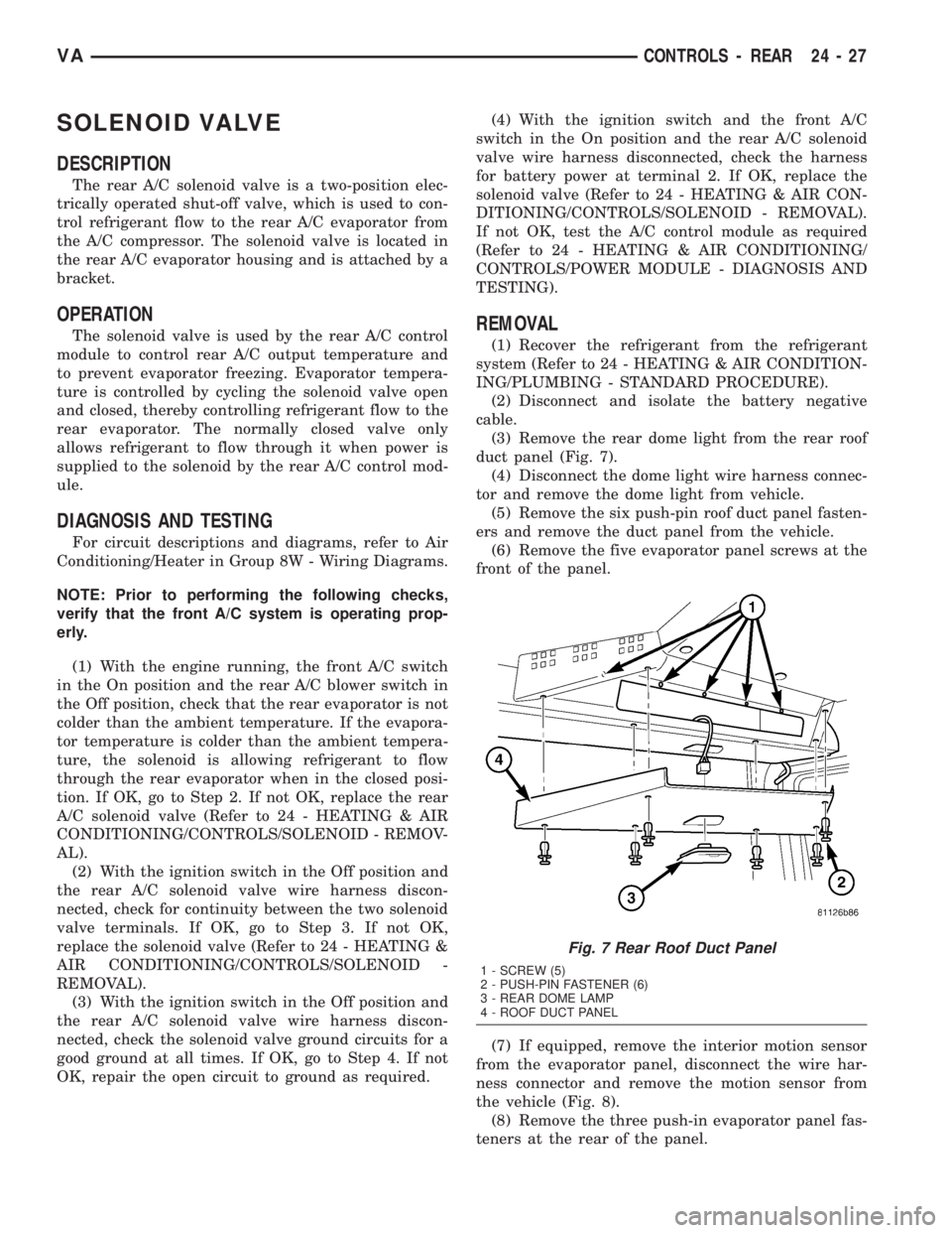
(3) Remove the rear dome light from the rear roof
duct panel (Fig. 7).
(4) Disconnect the dome light wire harness connec-
tor and remove the dome light from vehicle.
(5) Remove the six push-pin roof duct panel fasten-
ers and remove the duct panel from the vehicle.
(6) Remove the five evaporator panel screws at the
front of the panel.
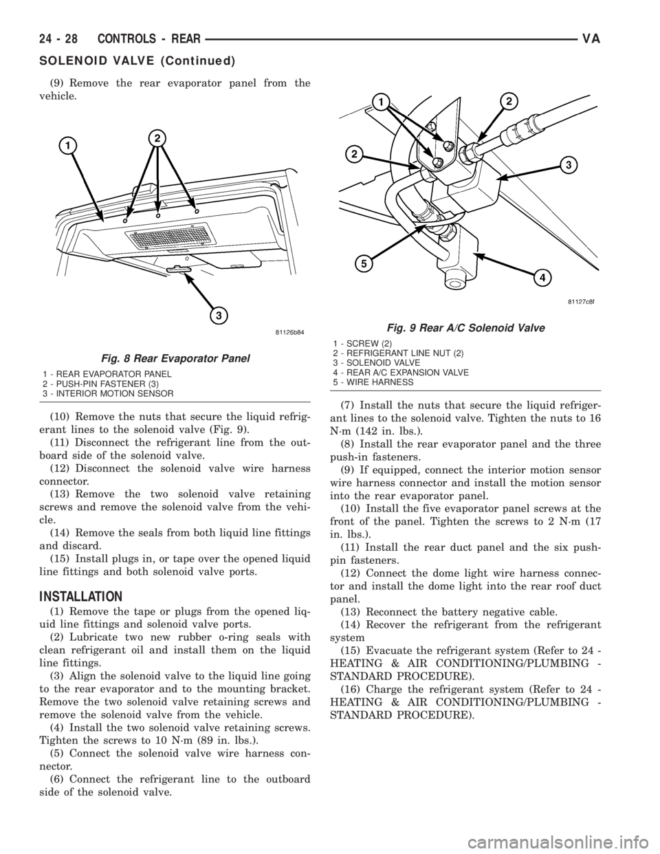
(7) If equipped, remove the interior motion sensor
from the evaporator panel, disconnect the wire har-
ness connector and remove the motion sensor from
the vehicle (Fig. 8).
(8) Remove the three push-in evaporator panel fas-
teners at the rear of the panel.
Fig. 7 Rear Roof Duct Panel
1 - SCREW (5)
2 - PUSH-PIN FASTENER (6)
3 - REAR DOME LAMP
4 - ROOF DUCT PANEL
VACONTROLS - REAR 24 - 27
Page 1156 of 1232
(9) Remove the rear evaporator panel from the
vehicle.
(10) Remove the nuts that secure the liquid refrig-
erant lines to the solenoid valve (Fig. 9).
(11) Disconnect the refrigerant line from the out-
board side of the solenoid valve.
(12) Disconnect the solenoid valve wire harness
connector.
(13) Remove the two solenoid valve retaining
screws and remove the solenoid valve from the vehi-
cle.
(14) Remove the seals from both liquid line fittings
and discard.
(15) Install plugs in, or tape over the opened liquid
line fittings and both solenoid valve ports.
INSTALLATION
(1) Remove the tape or plugs from the opened liq-
uid line fittings and solenoid valve ports.
(2) Lubricate two new rubber o-ring seals with
clean refrigerant oil and install them on the liquid
line fittings.
(3) Align the solenoid valve to the liquid line going
to the rear evaporator and to the mounting bracket.
Remove the two solenoid valve retaining screws and
remove the solenoid valve from the vehicle.
(4) Install the two solenoid valve retaining screws.
Tighten the screws to 10 N´m (89 in. lbs.).
(5) Connect the solenoid valve wire harness con-
nector.
(6) Connect the refrigerant line to the outboard
side of the solenoid valve.(7) Install the nuts that secure the liquid refriger-
ant lines to the solenoid valve. Tighten the nuts to 16
N´m (142 in. lbs.).
(8) Install the rear evaporator panel and the three
push-in fasteners.
(9) If equipped, connect the interior motion sensor
wire harness connector and install the motion sensor
into the rear evaporator panel.
(10) Install the five evaporator panel screws at the
front of the panel. Tighten the screws to 2 N´m (17
in. lbs.).
(11) Install the rear duct panel and the six push-
pin fasteners.
(12) Connect the dome light wire harness connec-
tor and install the dome light into the rear roof duct
panel.
(13) Reconnect the battery negative cable.
(14) Recover the refrigerant from the refrigerant
system
(15) Evacuate the refrigerant system (Refer to 24 -
HEATING & AIR CONDITIONING/PLUMBING -
STANDARD PROCEDURE).
(16) Charge the refrigerant system (Refer to 24 -
HEATING & AIR CONDITIONING/PLUMBING -
STANDARD PROCEDURE).
Fig. 8 Rear Evaporator Panel
1 - REAR EVAPORATOR PANEL
2 - PUSH-PIN FASTENER (3)
3 - INTERIOR MOTION SENSOR
Fig. 9 Rear A/C Solenoid Valve
1 - SCREW (2)
2 - REFRIGERANT LINE NUT (2)
3 - SOLENOID VALVE
4 - REAR A/C EXPANSION VALVE
5 - WIRE HARNESS
24 - 28 CONTROLS - REARVA
SOLENOID VALVE (Continued)
Page 1161 of 1232
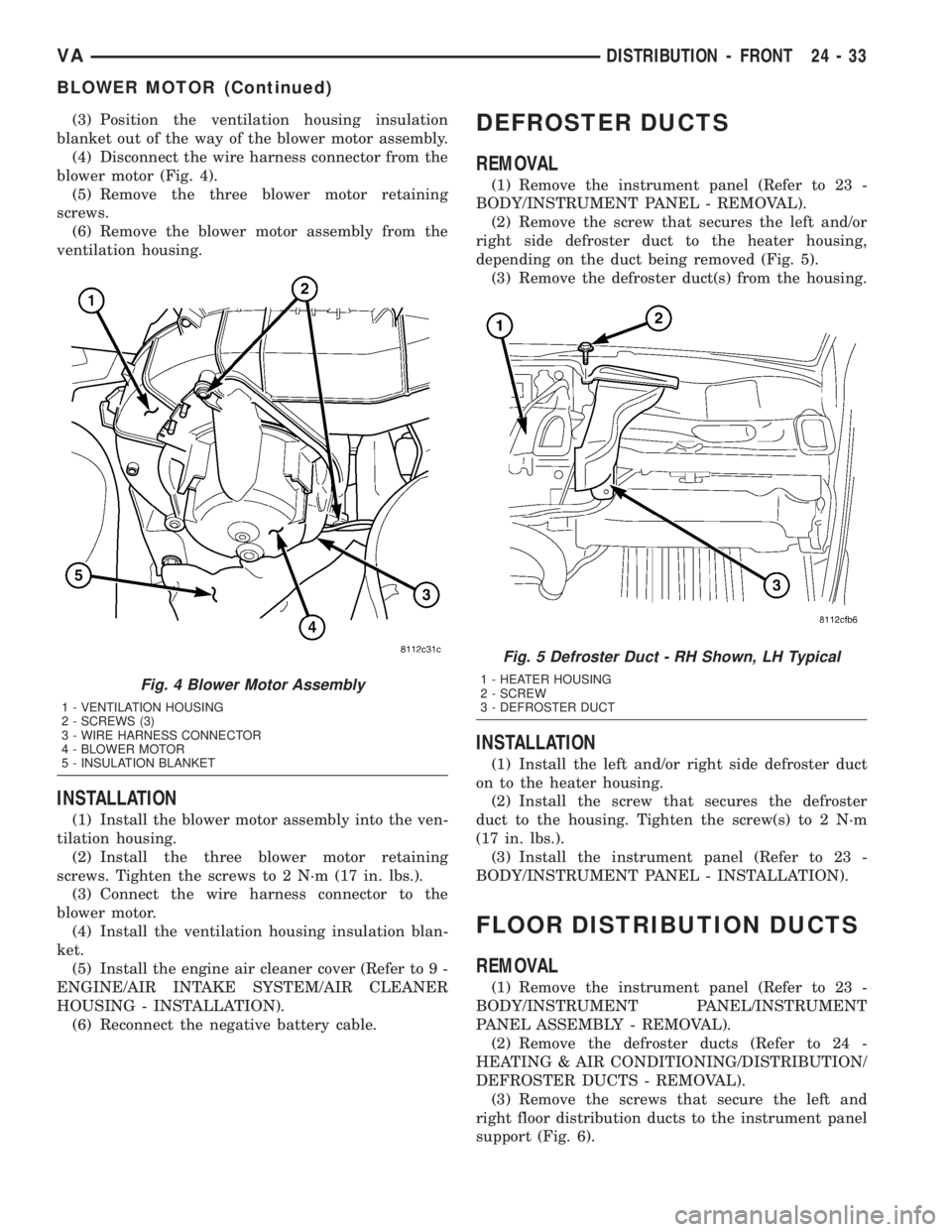
(3) Position the ventilation housing insulation
blanket out of the way of the blower motor assembly.
(4) Disconnect the wire harness connector from the
blower motor (Fig. 4).
(5) Remove the three blower motor retaining
screws.
(6) Remove the blower motor assembly from the
ventilation housing.
INSTALLATION
(1) Install the blower motor assembly into the ven-
tilation housing.
(2) Install the three blower motor retaining
screws. Tighten the screws to 2 N´m (17 in. lbs.).
(3) Connect the wire harness connector to the
blower motor.
(4) Install the ventilation housing insulation blan-
ket.
(5) Install the engine air cleaner cover (Refer to 9 -
ENGINE/AIR INTAKE SYSTEM/AIR CLEANER
HOUSING - INSTALLATION).
(6) Reconnect the negative battery cable.
DEFROSTER DUCTS
REMOVAL
(1) Remove the instrument panel (Refer to 23 -
BODY/INSTRUMENT PANEL - REMOVAL).
(2) Remove the screw that secures the left and/or
right side defroster duct to the heater housing,
depending on the duct being removed (Fig. 5).
(3) Remove the defroster duct(s) from the housing.
INSTALLATION
(1) Install the left and/or right side defroster duct
on to the heater housing.
(2) Install the screw that secures the defroster
duct to the housing. Tighten the screw(s) to 2 N´m
(17 in. lbs.).
(3) Install the instrument panel (Refer to 23 -
BODY/INSTRUMENT PANEL - INSTALLATION).
FLOOR DISTRIBUTION DUCTS
REMOVAL
(1) Remove the instrument panel (Refer to 23 -
BODY/INSTRUMENT PANEL/INSTRUMENT
PANEL ASSEMBLY - REMOVAL).
(2) Remove the defroster ducts (Refer to 24 -
HEATING & AIR CONDITIONING/DISTRIBUTION/
DEFROSTER DUCTS - REMOVAL).
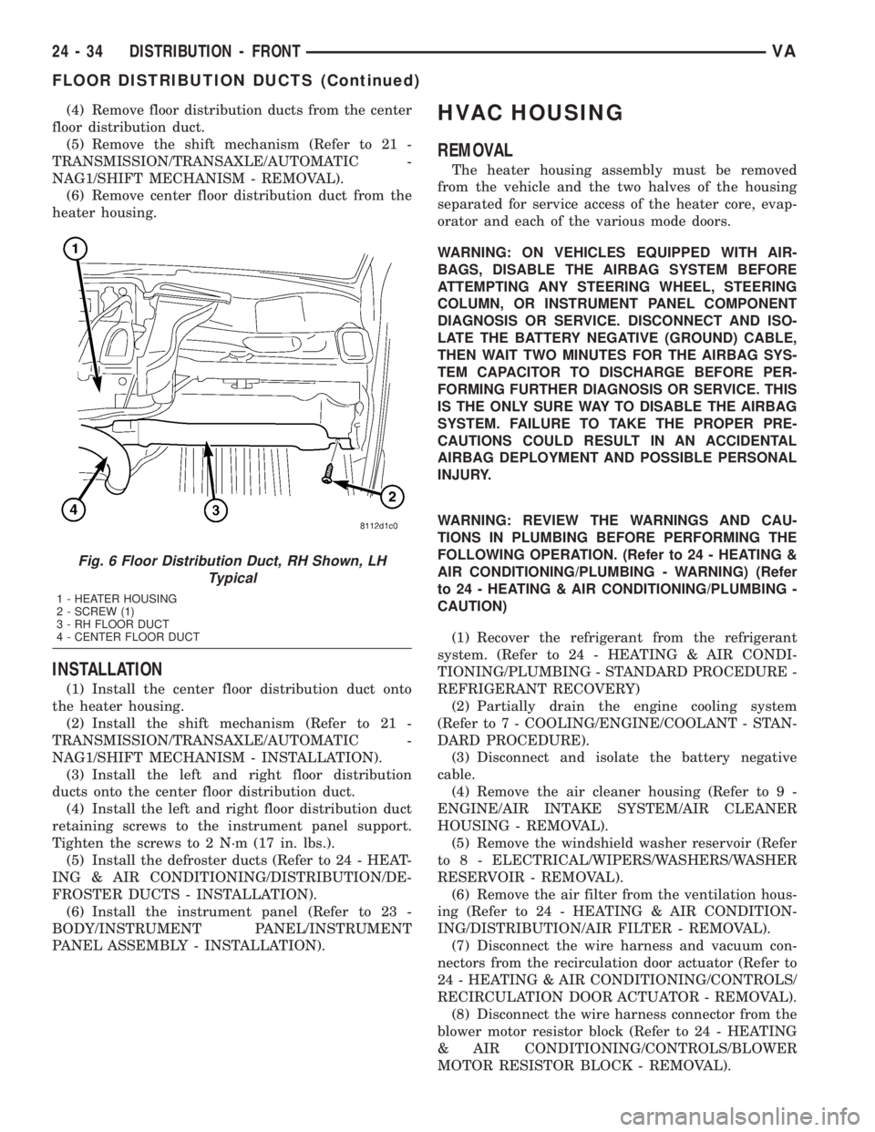
(3) Remove the screws that secure the left and
right floor distribution ducts to the instrument panel
support (Fig. 6).
Fig. 4 Blower Motor Assembly
1 - VENTILATION HOUSING
2 - SCREWS (3)
3 - WIRE HARNESS CONNECTOR
4 - BLOWER MOTOR
5 - INSULATION BLANKET
Fig. 5 Defroster Duct - RH Shown, LH Typical
1 - HEATER HOUSING
2 - SCREW
3 - DEFROSTER DUCT
VADISTRIBUTION - FRONT 24 - 33
BLOWER MOTOR (Continued)
Page 1162 of 1232
(4) Remove floor distribution ducts from the center
floor distribution duct.
(5) Remove the shift mechanism (Refer to 21 -
TRANSMISSION/TRANSAXLE/AUTOMATIC -
NAG1/SHIFT MECHANISM - REMOVAL).
(6) Remove center floor distribution duct from the
heater housing.
INSTALLATION
(1) Install the center floor distribution duct onto
the heater housing.
(2) Install the shift mechanism (Refer to 21 -
TRANSMISSION/TRANSAXLE/AUTOMATIC -
NAG1/SHIFT MECHANISM - INSTALLATION).
(3) Install the left and right floor distribution
ducts onto the center floor distribution duct.
(4) Install the left and right floor distribution duct
retaining screws to the instrument panel support.
Tighten the screws to 2 N´m (17 in. lbs.).
(5) Install the defroster ducts (Refer to 24 - HEAT-
ING & AIR CONDITIONING/DISTRIBUTION/DE-
FROSTER DUCTS - INSTALLATION).
(6) Install the instrument panel (Refer to 23 -
BODY/INSTRUMENT PANEL/INSTRUMENT
PANEL ASSEMBLY - INSTALLATION).
HVAC HOUSING
REMOVAL
The heater housing assembly must be removed
from the vehicle and the two halves of the housing
separated for service access of the heater core, evap-
orator and each of the various mode doors.
WARNING: ON VEHICLES EQUIPPED WITH AIR-
BAGS, DISABLE THE AIRBAG SYSTEM BEFORE
ATTEMPTING ANY STEERING WHEEL, STEERING
COLUMN, OR INSTRUMENT PANEL COMPONENT
DIAGNOSIS OR SERVICE. DISCONNECT AND ISO-
LATE THE BATTERY NEGATIVE (GROUND) CABLE,
THEN WAIT TWO MINUTES FOR THE AIRBAG SYS-
TEM CAPACITOR TO DISCHARGE BEFORE PER-
FORMING FURTHER DIAGNOSIS OR SERVICE. THIS
IS THE ONLY SURE WAY TO DISABLE THE AIRBAG
SYSTEM. FAILURE TO TAKE THE PROPER PRE-
CAUTIONS COULD RESULT IN AN ACCIDENTAL
AIRBAG DEPLOYMENT AND POSSIBLE PERSONAL
INJURY.
WARNING: REVIEW THE WARNINGS AND CAU-
TIONS IN PLUMBING BEFORE PERFORMING THE
FOLLOWING OPERATION. (Refer to 24 - HEATING &
AIR CONDITIONING/PLUMBING - WARNING) (Refer
to 24 - HEATING & AIR CONDITIONING/PLUMBING -
CAUTION)
(1) Recover the refrigerant from the refrigerant
system. (Refer to 24 - HEATING & AIR CONDI-
TIONING/PLUMBING - STANDARD PROCEDURE -
REFRIGERANT RECOVERY)
(2) Partially drain the engine cooling system
(Refer to 7 - COOLING/ENGINE/COOLANT - STAN-
DARD PROCEDURE).
(3) Disconnect and isolate the battery negative
cable.
(4) Remove the air cleaner housing (Refer to 9 -
ENGINE/AIR INTAKE SYSTEM/AIR CLEANER
HOUSING - REMOVAL).
(5) Remove the windshield washer reservoir (Refer
to 8 - ELECTRICAL/WIPERS/WASHERS/WASHER
RESERVOIR - REMOVAL).
(6) Remove the air filter from the ventilation hous-
ing (Refer to 24 - HEATING & AIR CONDITION-
ING/DISTRIBUTION/AIR FILTER - REMOVAL).
(7) Disconnect the wire harness and vacuum con-
nectors from the recirculation door actuator (Refer to
24 - HEATING & AIR CONDITIONING/CONTROLS/
RECIRCULATION DOOR ACTUATOR - REMOVAL).
(8) Disconnect the wire harness connector from the
blower motor resistor block (Refer to 24 - HEATING
& AIR CONDITIONING/CONTROLS/BLOWER
MOTOR RESISTOR BLOCK - REMOVAL).
Fig. 6 Floor Distribution Duct, RH Shown, LH
Typical
1 - HEATER HOUSING
2 - SCREW (1)
3 - RH FLOOR DUCT
4 - CENTER FLOOR DUCT
24 - 34 DISTRIBUTION - FRONTVA
FLOOR DISTRIBUTION DUCTS (Continued)
Page 1163 of 1232
(9) Disconnect the wire harness connector from the
blower motor (Refer to 24 - HEATING & AIR CON-
DITIONING/DISTRIBUTION/BLOWER MOTOR -
REMOVAL).
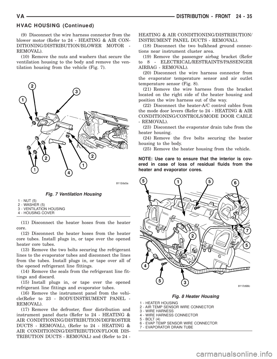
(10) Remove the nuts and washers that secure the
ventilation housing to the body and remove the ven-
tilation housing from the vehicle (Fig. 7).
(11) Disconnect the heater hoses from the heater
core.
(12) Disconnect the heater hoses from the heater
core tubes. Install plugs in, or tape over the opened
heater core tubes.
(13) Remove the two bolts securing the refrigerant
lines to the evaporator tubes and disconnect the lines
from the tubes. Install plugs in, or tape over all of
the opened refrigerant line fittings.
(14) Remove the seals from the refrigerant line fit-
tings and discard.
(15) Install plugs in, or tape over the opened
refrigerant line fittings and evaporator tubes.
(16) Remove the instrument panel from the vehi-
cle(Refer to 23 - BODY/INSTRUMENT PANEL -
REMOVAL).
(17) Remove the defroster, floor distribution and
instrument panel ducts (Refer to 24 - HEATING &
AIR CONDITIONING/DISTRIBUTION/DEFROSTER
DUCTS - REMOVAL), (Refer to 24 - HEATING &
AIR CONDITIONING/DISTRIBUTION/FLOOR DIS-
TRIBUTION DUCTS - REMOVAL) and (Refer to 24 -HEATING & AIR CONDITIONING/DISTRIBUTION/
INSTRUMENT PANEL DUCTS - REMOVAL).
(18) Disconnect the two bulkhead ground connec-
tions near instrument cluster area.
(19) Remove the passenger airbag bracket (Refer
to 8 - ELECTRICAL/RESTRAINTS/PASSENGER
AIRBAG - REMOVAL).
(20) Disconnect the wire harness connector from
the evaporator temperature sensor and air outlet
temperature sensor (Fig. 8).
(21) Remove the wire harness from the bracket
located on the right side of the heater housing and
position the wire harness out of the way.
(22) Disconnect the heater-A/C control cables from
the mode door levers (Refer to 24 - HEATING & AIR
CONDITIONING/CONTROLS/MODE DOOR CABLE
- REMOVAL).
(23) Disconnect the evaporator drain tube from the
heater housing.
(24) Remove the five bolts securing the heater
housing to the body.
(25) Remove the heater housing from the vehicle.
NOTE: Use care to ensure that the interior is cov-
ered in case of loss of residual fluids from the
heater and evaporator cores.
Fig. 7 Ventilation Housing
1 - NUT (5)
2 - WASHER (5)
3 - VENTILATION HOUSING
4 - HOUSING COVER
Fig. 8 Heater Housing
1 - HEATER HOUSING
2 - AIR TEMP SENSOR WIRE CONNECTOR
3 - WIRE HARNESS
4 - WIRE HARNESS CONNECTOR
5 - BOLT (4)
6 - EVAP TEMP SENSOR WIRE CONNECTOR
7 - EVAPORATOR DRAIN TUBE
VADISTRIBUTION - FRONT 24 - 35
HVAC HOUSING (Continued)
Page 1164 of 1232
DISASSEMBLY
(1) Remove the heater and ventilation housings
from the vehicle (Refer to 24 - HEATING & AIR
CONDITIONING/DISTRIBUTION/HVAC HOUSING
- REMOVAL).
(2) Place the heater housing in the upright posi-
tion on a work bench, making allowance for leakage
of fluids.
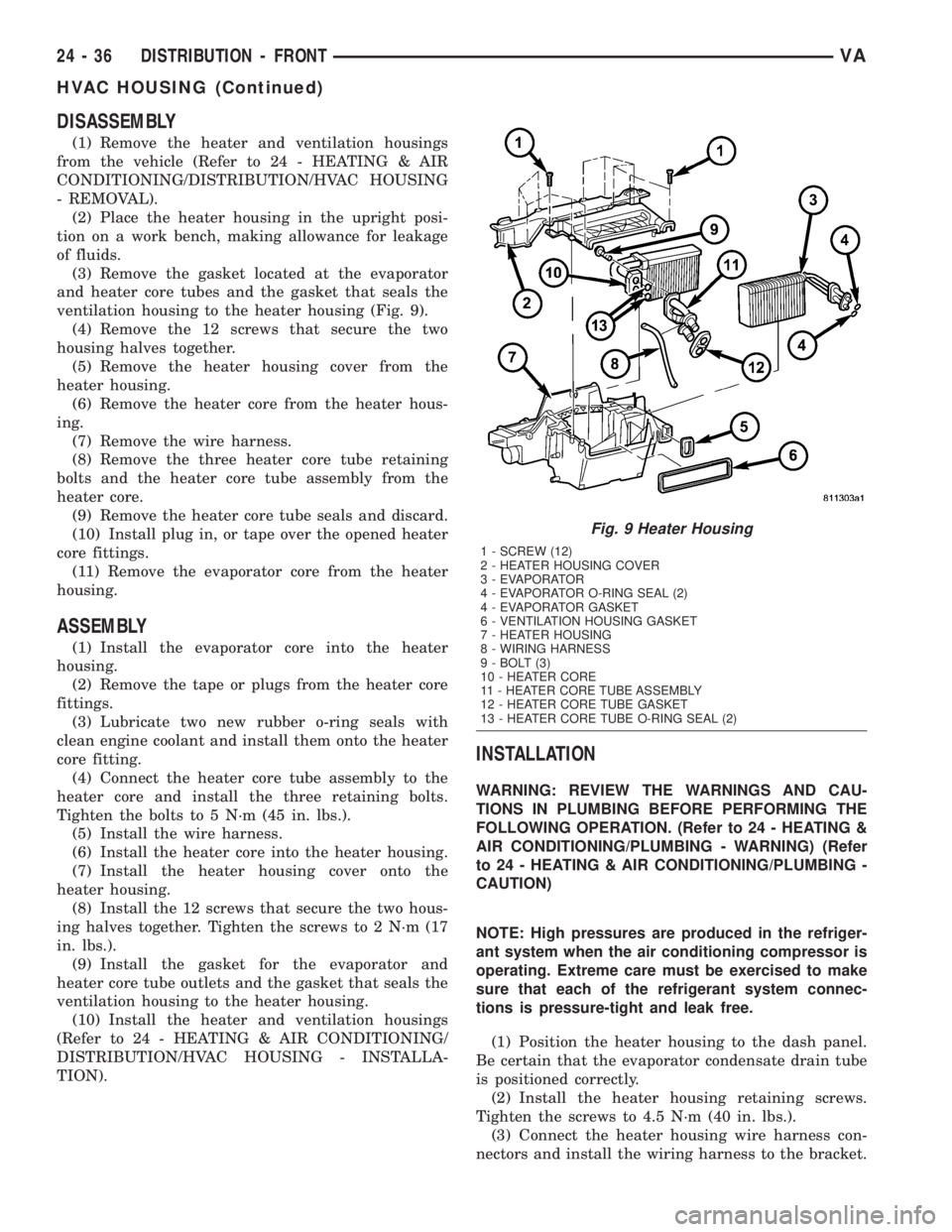
(3) Remove the gasket located at the evaporator
and heater core tubes and the gasket that seals the
ventilation housing to the heater housing (Fig. 9).
(4) Remove the 12 screws that secure the two
housing halves together.
(5) Remove the heater housing cover from the
heater housing.
(6) Remove the heater core from the heater hous-
ing.
(7) Remove the wire harness.
(8) Remove the three heater core tube retaining
bolts and the heater core tube assembly from the
heater core.
(9) Remove the heater core tube seals and discard.
(10) Install plug in, or tape over the opened heater
core fittings.
(11) Remove the evaporator core from the heater
housing.
ASSEMBLY
(1) Install the evaporator core into the heater
housing.
(2) Remove the tape or plugs from the heater core
fittings.
(3) Lubricate two new rubber o-ring seals with
clean engine coolant and install them onto the heater
core fitting.
(4) Connect the heater core tube assembly to the
heater core and install the three retaining bolts.
Tighten the bolts to 5 N´m (45 in. lbs.).
(5) Install the wire harness.
(6) Install the heater core into the heater housing.
(7) Install the heater housing cover onto the
heater housing.
(8) Install the 12 screws that secure the two hous-
ing halves together. Tighten the screws to 2 N´m (17
in. lbs.).
(9) Install the gasket for the evaporator and
heater core tube outlets and the gasket that seals the
ventilation housing to the heater housing.
(10) Install the heater and ventilation housings
(Refer to 24 - HEATING & AIR CONDITIONING/
DISTRIBUTION/HVAC HOUSING - INSTALLA-
TION).
INSTALLATION
WARNING: REVIEW THE WARNINGS AND CAU-
TIONS IN PLUMBING BEFORE PERFORMING THE
FOLLOWING OPERATION. (Refer to 24 - HEATING &
AIR CONDITIONING/PLUMBING - WARNING) (Refer
to 24 - HEATING & AIR CONDITIONING/PLUMBING -
CAUTION)
NOTE: High pressures are produced in the refriger-
ant system when the air conditioning compressor is
operating. Extreme care must be exercised to make
sure that each of the refrigerant system connec-
tions is pressure-tight and leak free.
(1) Position the heater housing to the dash panel.
Be certain that the evaporator condensate drain tube
is positioned correctly.
(2) Install the heater housing retaining screws.
Tighten the screws to 4.5 N´m (40 in. lbs.).
(3) Connect the heater housing wire harness con-
nectors and install the wiring harness to the bracket.
Fig. 9 Heater Housing
1 - SCREW (12)
2 - HEATER HOUSING COVER
3 - EVAPORATOR
4 - EVAPORATOR O-RING SEAL (2)
4 - EVAPORATOR GASKET
6 - VENTILATION HOUSING GASKET
7 - HEATER HOUSING
8 - WIRING HARNESS
9 - BOLT (3)
10 - HEATER CORE
11 - HEATER CORE TUBE ASSEMBLY
12 - HEATER CORE TUBE GASKET
13 - HEATER CORE TUBE O-RING SEAL (2)
24 - 36 DISTRIBUTION - FRONTVA
HVAC HOUSING (Continued)