2005 MERCEDES-BENZ SPRINTER heating
[x] Cancel search: heatingPage 735 of 1232
hard wiring and bus bars. Internal relays and micro
processors allow the vehicle electronics to control
some of the power distribution circuits throughout
the vehicle. Refer to the Wiring section for complete
circuit diagrams.
REMOVAL
(1) Disconnect and isolate the negative battery
cable.
(2) Remove fuse block cover by rotating locking
screw 90É.
(3) Remove the steering column cover. Refer to the
Body section for the procedure.
(4) Unscrew fuse block connections and disconnect
all electrical connectors from the fuse block.
(5) Remove the fuse block from the steering col-
umn.
INSTALLATION
(1) Position the fuse block in the steering column.
(2) Install fuse block connections and connect all
electrical connectors on the fuse block.
(3) Install the steering column cover. Refer to the
Body section for the procedure.
(4) Install fuse block cover by rotating locking
screw 90É.
(5) Connect the negative battery cable.
(6) Set time and radio stations.
FUSE BLOCK #2
DESCRIPTION
An electrical fuse block is concealed under the
driver side front seat. The fuse block serves to dis-
tribute electrical current to many of the electrical
systems in the vehicle. The fuse block houses blade-
type mini fuses, blade-type automatic resetting cir-
cuit breakers and International Standards
Organization relays. Additional provisions are avail-
able in the fuse block for additional fuses and ISO
relays.
The molded plastic fuse block housing has an inte-
gral mounting bracket that is secured with screws to
the seat base. The driver side seat base also has a
snap-fit fuse access panel that can be removed for
service of the fuses and the relays. A finger recess is
molded into one end for easy removal. A fuse layout
map is molded onto the back side of the panel to
ensure proper fuse identification.
The fuse block is integral to the body wire harness.
If any internal circuit or the fuse block housing is
faulty or damaged, the entire fuse block and body
wire harness unit must be replaced.
OPERATION
All of the circuits entering and leaving the fuse
block do so through the body wire harness. Internal
connection of all of the fuse block circuits is accom-
plished by an intricate combination of hard wiring
and bus bars.
POWER DISTRIBUTION
CENTER
DESCRIPTION
All of the electrical current distributed throughout
this vehicle is directed through the Power Distribu-
tion Center (PDC). The molded plastic PDC housing
is located in the left front corner of the engine com-
partment, on the battery positive cable. The PDC
housing has a molded plastic cover that slides over
the PDC housing. The PDC cover is easily opened or
removed for service access.
The PDC unit cannot be repaired and is only ser-
viced as a unit with the headlamp and dash wire
harness. If the internal circuits or the PDC housing
are faulty or damaged, the headlamp and dash wire
harness unit must be replaced.
OPERATION
All of the current from the battery and the gener-
ator output enters the PDC through the positive bat-
tery cable. The PDC cover is removed to access the
battery and generator output connection B(+) termi-
nal studs. Internal connection of all of the PDC cir-
cuits is accomplished by an intricate combination of
hard wiring and bus bars. Refer to Wiring Diagrams
for the location of complete PDC circuit diagrams.
POWER OUTLET
DESCRIPTION
The power outlet is installed in the instrument
panel accessory switch plate, which is located near
the center of the instrument panel. The power outlet
base is secured by a snap fit within the instrument
panel. A plastic protective cap snaps over the power
outlet base when the power outlet is not being used.
While the power outlet is very similar to a cigar
lighter base unit, it does not include the two small
spring-clip retainers inside the bottom of the recepta-
cle shell that are used to secure the cigar lighter
heating element to the insulated contact.
The power outlet receptacle unit are available for
service. The power outlet receptacle cannot be
repaired and, if faulty or damaged, it must be
replaced.
VA8W-97 POWER DISTRIBUTION 8W - 97 - 3
FUSE BLOCK #1 (Continued)
Page 743 of 1232
(2) Remove the hood.
(3) Drain cooling system (Refer to 7 - COOLING/
ENGINE/COOLANT - STANDARD PROCEDURE).
(4) Evacuate and recover air conditioning system
(Refer to 24 - HEATING & AIR CONDITIONING/
PLUMBING - STANDARD PROCEDURE).
(5) Disconnect the engine wiring harness at the
vehicle side and carefully guide though the cowl into
the engine area.
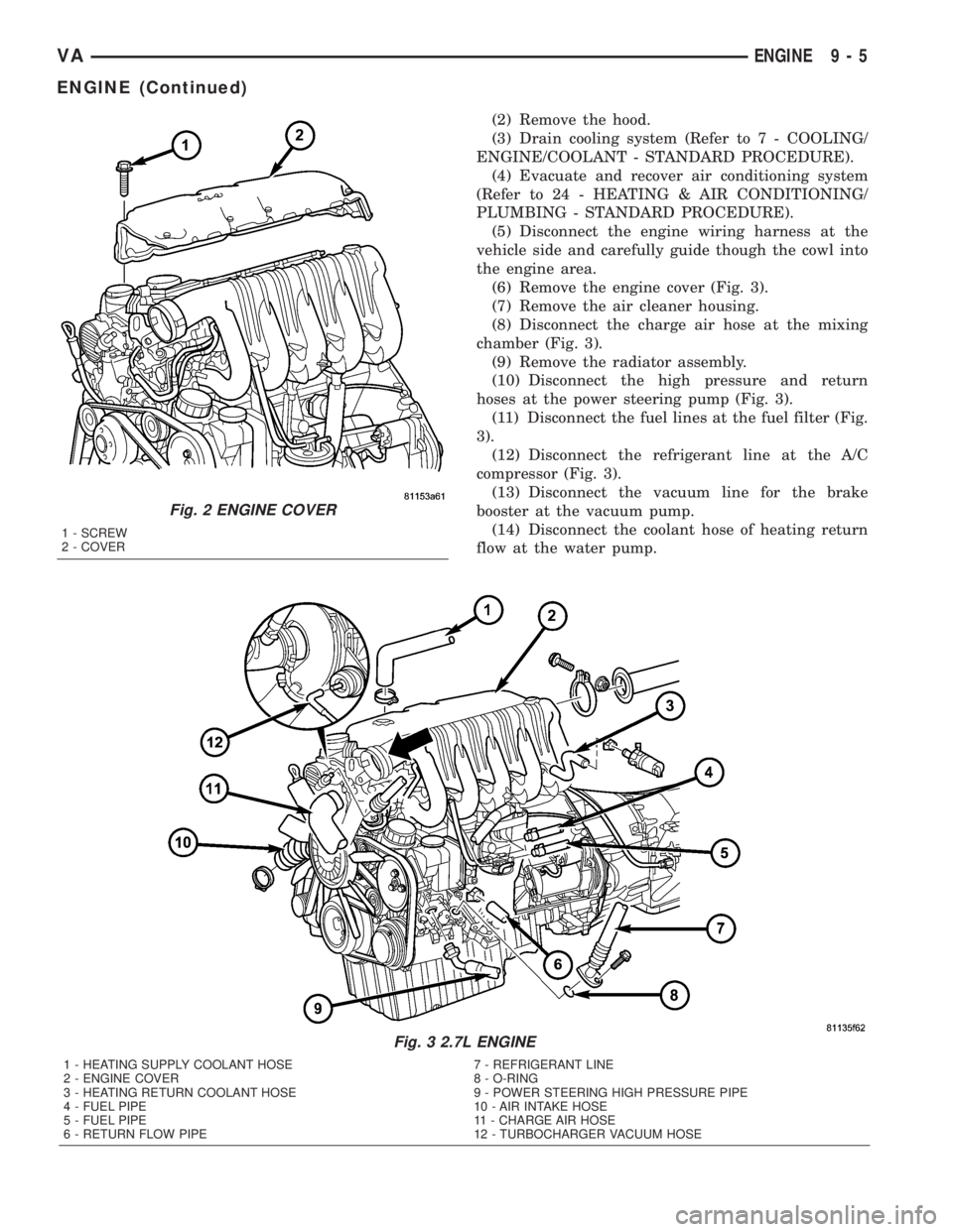
(6) Remove the engine cover (Fig. 3).
(7) Remove the air cleaner housing.
(8) Disconnect the charge air hose at the mixing
chamber (Fig. 3).
(9) Remove the radiator assembly.
(10) Disconnect the high pressure and return
hoses at the power steering pump (Fig. 3).
(11) Disconnect the fuel lines at the fuel filter (Fig.
3).
(12) Disconnect the refrigerant line at the A/C
compressor (Fig. 3).
(13) Disconnect the vacuum line for the brake
booster at the vacuum pump.
(14) Disconnect the coolant hose of heating return
flow at the water pump.
Fig. 3 2.7L ENGINE
1 - HEATING SUPPLY COOLANT HOSE 7 - REFRIGERANT LINE
2 - ENGINE COVER 8 - O-RING
3 - HEATING RETURN COOLANT HOSE 9 - POWER STEERING HIGH PRESSURE PIPE
4 - FUEL PIPE 10 - AIR INTAKE HOSE
5 - FUEL PIPE 11 - CHARGE AIR HOSE
6 - RETURN FLOW PIPE 12 - TURBOCHARGER VACUUM HOSE
Fig. 2 ENGINE COVER
1 - SCREW
2 - COVER
VAENGINE 9 - 5
ENGINE (Continued)
Page 773 of 1232
CRANKSHAFT
STANDARD PROCEDURE - MEASURE
CRANKSHAFT AND BLOCK JOURNALS
NOTE: After any bearing damage occurred, remove
all debris which is present in the main oil gallery,
connecting rod bores, and in the crankshaft and oil
galleries. Include removal of the inserting steel ball
of the main oil gallery before cleaning.
(1) Remove crankshaft (Refer to 9 - ENGINE/EN-
GINE BLOCK/CRANKSHAFT - REMOVAL).
(2) Clean all engine parts thoroughly.
CAUTION: After bearing has damage has occurred,
replace connecting rods which have suffered over-
heating because of bearing damage. The connect-
ing rod must not have any cross scores and
notches.
(3) Inspect connecting rod. If damage is present,
inspect crankshaft, replace as necessary.
(4) Inspect crankcase.
(5) Inspect standard size of crankshaft bearing
shells.
(6) Inspect crankshaft bearing cap.
(7) Mount crankshaft radially.(8) Inspect crankshaft bearing play.
NOTE: Radial mounting of the main bearings of
standard size crankshaft is possible by assigning
the color-coded bearing shells.
ASSIGN CRANKSHAFT BEARING SHELLS
The oil pan rail of the cylinder block is marked
with chisel punches indicating what bearing shell are
used.
(9) Assign crankshaft bearing shells.
(10) Mount crankshaft axially.
(11) Inspect crankshaft bearing play.
REMOVAL
(1) Remove engine (Refer to 9 - ENGINE -
REMOVAL).
(2) Remove timing case cover (Refer to 9 -
ENGINE/VALVE TIMING/TIMING BELT / CHAIN
COVER(S) - REMOVAL)
(3) Remove end cover.(Refer to 9 - ENGINE/EN-
GINE BLOCK/CRANKSHAFT OIL SEAL - REAR -
REMOVAL).
(4) Remove pistons (Refer to 9 - ENGINE/ENGINE
BLOCK/PISTON & CONNECTING ROD - REMOV-
AL).
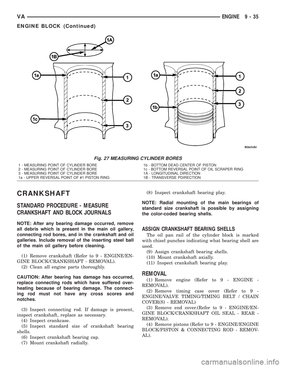
Fig. 27 MEASURING CYLINDER BORES
1 - MEASURING POINT OF CYLINDER BORE
2 - MEASURING POINT OF CYLINDER BORE
3 - MEASURING POINT OF CYLINDER BORE
1a - UPPER REVERSAL POINT OF #1 PISTON RING1b - BOTTOM DEAD CENTER OF PISTON
1c - BOTTOM REVERSAL POINT OF OIL SCRAPER RING
1A - LONGITUDINAL DIRECTION
1B - TRANSVERSE PDIRECTION
VAENGINE 9 - 35
ENGINE BLOCK (Continued)
Page 833 of 1232
SPECIAL TOOLS
FUEL SYSTEM
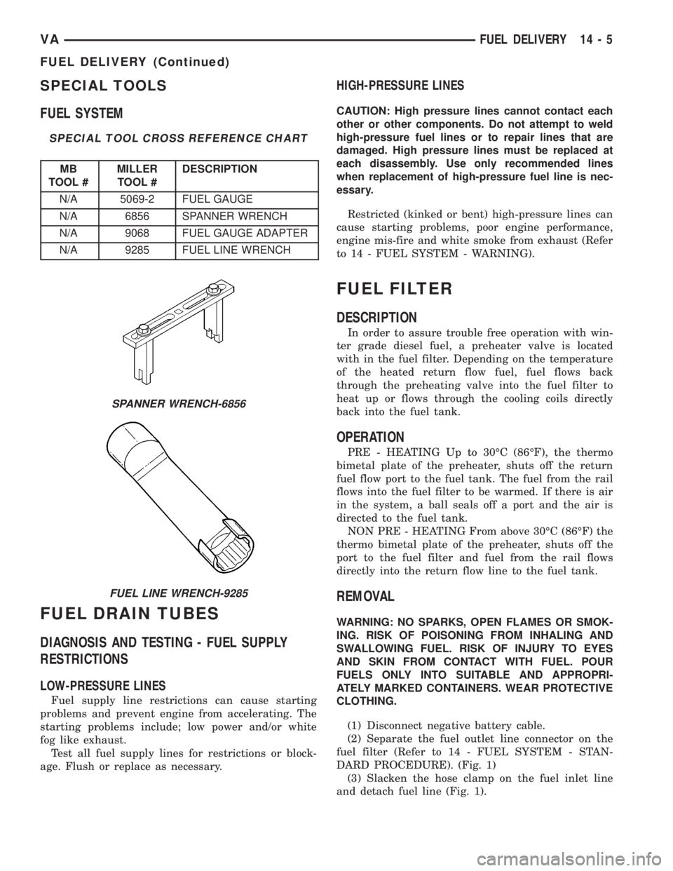
SPECIAL TOOL CROSS REFERENCE CHART
MB
TOOL #MILLER
TOOL #DESCRIPTION
N/A 5069-2 FUEL GAUGE
N/A 6856 SPANNER WRENCH
N/A 9068 FUEL GAUGE ADAPTER
N/A 9285 FUEL LINE WRENCH
FUEL DRAIN TUBES
DIAGNOSIS AND TESTING - FUEL SUPPLY
RESTRICTIONS
LOW-PRESSURE LINES
Fuel supply line restrictions can cause starting
problems and prevent engine from accelerating. The
starting problems include; low power and/or white
fog like exhaust.
Test all fuel supply lines for restrictions or block-
age. Flush or replace as necessary.
HIGH-PRESSURE LINES
CAUTION: High pressure lines cannot contact each
other or other components. Do not attempt to weld
high-pressure fuel lines or to repair lines that are
damaged. High pressure lines must be replaced at
each disassembly. Use only recommended lines
when replacement of high-pressure fuel line is nec-
essary.
Restricted (kinked or bent) high-pressure lines can
cause starting problems, poor engine performance,
engine mis-fire and white smoke from exhaust (Refer
to 14 - FUEL SYSTEM - WARNING).
FUEL FILTER
DESCRIPTION
In order to assure trouble free operation with win-
ter grade diesel fuel, a preheater valve is located
with in the fuel filter. Depending on the temperature
of the heated return flow fuel, fuel flows back
through the preheating valve into the fuel filter to
heat up or flows through the cooling coils directly
back into the fuel tank.
OPERATION
PRE - HEATING Up to 30ÉC (86ÉF), the thermo
bimetal plate of the preheater, shuts off the return
fuel flow port to the fuel tank. The fuel from the rail
flows into the fuel filter to be warmed. If there is air
in the system, a ball seals off a port and the air is
directed to the fuel tank.
NON PRE - HEATING From above 30ÉC (86ÉF) the
thermo bimetal plate of the preheater, shuts off the
port to the fuel filter and fuel from the rail flows
directly into the return flow line to the fuel tank.
REMOVAL
WARNING: NO SPARKS, OPEN FLAMES OR SMOK-
ING. RISK OF POISONING FROM INHALING AND
SWALLOWING FUEL. RISK OF INJURY TO EYES
AND SKIN FROM CONTACT WITH FUEL. POUR
FUELS ONLY INTO SUITABLE AND APPROPRI-
ATELY MARKED CONTAINERS. WEAR PROTECTIVE
CLOTHING.
(1) Disconnect negative battery cable.
(2) Separate the fuel outlet line connector on the
fuel filter (Refer to 14 - FUEL SYSTEM - STAN-
DARD PROCEDURE). (Fig. 1)
(3) Slacken the hose clamp on the fuel inlet line
and detach fuel line (Fig. 1).
SPANNER WRENCH-6856
FUEL LINE WRENCH-9285
VAFUEL DELIVERY 14 - 5
FUEL DELIVERY (Continued)
Page 834 of 1232
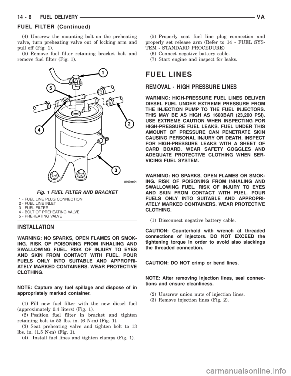
(4) Unscrew the mounting bolt on the preheating
valve, turn preheating valve out of locking arm and
pull off (Fig. 1).
(5) Remove fuel filter retaining bracket bolt and
remove fuel filter (Fig. 1).
INSTALLATION
WARNING: NO SPARKS, OPEN FLAMES OR SMOK-
ING. RISK OF POISONING FROM INHALING AND
SWALLOWING FUEL. RISK OF INJURY TO EYES
AND SKIN FROM CONTACT WITH FUEL. POUR
FUELS ONLY INTO SUITABLE AND APPROPRI-
ATELY MARKED CONTAINERS. WEAR PROTECTIVE
CLOTHING.
NOTE: Capture any fuel spillage and dispose of in
appropriately marked container.
(1) Fill new fuel filter with the new diesel fuel
(approximately 0.4 liters) (Fig. 1).
(2) Position fuel filter in bracket and tighten
retaining bolt to 53 lbs. in. (6 N´m) (Fig. 1).
(3) Seat preheating valve and tighten bolt to 13
lbs. in. (1.5 N´m) (Fig. 1).
(4) Install fuel lines and tighten clamps (Fig. 1).(5) Properly seat fuel line plug connection and
properly set release arm (Refer to 14 - FUEL SYS-
TEM - STANDARD PROCEDURE)
(6) Connect negative battery cable.
(7) Start engine and inspect for leaks.
FUEL LINES
REMOVAL - HIGH PRESSURE LINES
WARNING: HIGH-PRESSURE FUEL LINES DELIVER
DIESEL FUEL UNDER EXTREME PRESSURE FROM
THE INJECTION PUMP TO THE FUEL INJECTORS.
THIS MAY BE AS HIGH AS 1600BAR (23,200 PSI).
USE EXTREME CAUTION WHEN INSPECTING FOR
HIGH-PRESSURE FUEL LEAKS. FUEL UNDER THIS
AMOUNT OF PRESSURE CAN PENETRATE SKIN
CAUSING PERSONAL INJURY OR DEATH. INSPECT
FOR HIGH-PRESSURE LEAKS WITH A SHEET OF
CARD BOARD. WEAR SAFETY GOGGLES AND
ADEQUATE PROTECTIVE CLOTHING WHEN SER-
VICING FUEL SYSTEM.
WARNING: NO SPARKS, OPEN FLAMES OR SMOK-
ING. RISK OF POISONING FROM INHALING AND
SWALLOWING FUEL. RISK OF INJURY TO EYES
AND SKIN FROM CONTACT WITH FUEL. POUR
FUELS ONLY INTO SUITABLE AND APPROPRI-
ATELY MARKED CONTAINERS. WEAR PROTECTIVE
CLOTHING.
(1) Disconnect negative battery cable.
CAUTION: Counterhold with wrench at threaded
connections of injectors. DO NOT EXCEED the
tightening torque in order to avoid also slackings
the threaded connection.
CAUTION: DO NOT crimp or bend lines.
NOTE: After removing injection lines, seal connec-
tions and ensure cleanliness.
(2) Unscrew union nuts of injection lines.
(3) Remove injection lines (Fig. 2).
Fig. 1 FUEL FILTER AND BRACKET
1 - FUEL LINE PLUG CONNECTION
2 - FUEL LINE INLET
3 - FUEL FILTER
4 - BOLT OF PREHEATING VALVE
5 - PREHEATING VALVE
14 - 6 FUEL DELIVERYVA
FUEL FILTER (Continued)
Page 851 of 1232
NOTE: Always replace the seals that seal off the
injectors at the cylinder head to the combustion
chamber and replace the retaining screws.
REMOVAL
WARNING: HIGH-PRESSURE FUEL LINES DELIVER
DIESEL FUEL UNDER EXTREME PRESSURE FROM
THE INJECTION PUMP TO THE FUEL INJECTORS.
THIS MAY BE AS HIGH AS 1600BAR (23,200 PSI).
USE EXTREME CAUTION WHEN INSPECTING FOR
HIGH-PRESSURE FUEL LEAKS. FUEL UNDER THIS
AMOUNT OF PRESSURE CAN PENETRATE SKIN
CAUSING PERSONAL INJURY OR DEATH. INSPECT
FOR HIGH-PRESSURE LEAKS WITH A SHEET OF
CARD BOARD. WEAR SAFETY GOGGLES AND
ADEQUATE PROTECTIVE CLOTHING WHEN SER-
VICING FUEL SYSTEM.
WARNING: NO SPARKS, OPEN FLAMES OR SMOK-
ING. RISK OF POISONING FROM INHALING AND
SWALLOWING FUEL. RISK OF INJURY TO EYES
AND SKIN FROM CONTACT WITH FUEL. POUR
FUELS ONLY INTO SUITABLE AND APPROPRI-
ATELY MARKED CONTAINERS. WEAR PROTECTIVE
CLOTHING.
NOTE: The engine must be lowered in the vehicle to
remove the fourth and fifth cylinders fuel injectors.
(1) Disconnect negative battery cable.
(2) Remove engine cover (Refer to 9 - ENGINE -
REMOVAL).
(3) Raise and suitably support the vehicle.
(4) Remove lower radiator deflector plate.
(5) Drain cooling system (Refer to 7 - COOLING/
ENGINE/COOLANT - STANDARD PROCEDURE).
(6) Remove turbocharger down pipe assembly.
(7) Remove oil dipstick tube retaining bolt and pull
tube from oil pan.
(8) Lower vehicle.
(9) Remove upper radiator hose.
(10) Remove air cleaner box assembly and hoses.
(11) Remove charge air cooler inlet hose.
(12) Remove charge air cooler to turbocharger inlet
adaptor.
(13) Remove turbocharger to right engine mount
bracket.
(14) Disconnect steering coupler at gear box (RHD
Only).
(15) Remove battery (Refer to 8 - ELECTRICAL/
BATTERY SYSTEM/BATTERY - REMOVAL).
(16) Unclip PDC from battery tray and set aside.(17) Remove battery tray (Refer to 8 - ELECTRI-
CAL/BATTERY SYSTEM/TRAY - REMOVAL).
(18) Remove power steering reservoir (Refer to 19 -
STEERING/PUMP/RESERVOIR - REMOVAL).
(19) Remove charger air cooler outlet hose.
(20) Remove intake manifold to left engine mount
bracket.
(21) Evacuate air conditioning system (Refer to 24
- HEATING & AIR CONDITIONING/PLUMBING -
STANDARD PROCEDURE).
(22) Disconnect air conditioning suction / discharge
lines at A/C compressor.
(23) Disconnect pedal position sensor electrical
connector.
(24) Unplug injector electrical connectors.
(25) Remove fuel / water separator to intake man-
ifold retaining bolts.
(26) Support engine with hoist.
(27) Remove engine mount through bolts.
(28) Remove right engine mount sill plate.
NOTE: Counterhold injection lines with wrench
socket at threaded connections of injectors.
(29) Disconnect fuel injector high pressure line.
(30) Remove fuel injector retaining bolt and ten-
sion claw.
(31) Suitably lower engine to gain fuel injector
access and remove injector.
NOTE: If injectors are tight, remove with extraction
claw in place of tensioning claw. If extraction claw
contacts cylinder head cover, remove cylinder head
cover. If necessary, remove injectors with threaded
adaptor and discard injector.
(32) Remove injectors (Fig. 10).
(33) Clean injectors and recesses (Refer to 14 -
FUEL SYSTEM/FUEL INJECTION/FUEL INJEC-
TOR - STANDARD PROCEDURE).
INSTALLATION
WARNING: HIGH-PRESSURE FUEL LINES DELIVER
DIESEL FUEL UNDER EXTREME PRESSURE FROM
THE INJECTION PUMP TO THE FUEL INJECTORS.
THIS MAY BE AS HIGH AS 1600BAR (23,200 PSI).
USE EXTREME CAUTION WHEN INSPECTING FOR
HIGH-PRESSURE FUEL LEAKS. FUEL UNDER THIS
AMOUNT OF PRESSURE CAN PENETRATE SKIN
CAUSING PERSONAL INJURY OR DEATH. INSPECT
FOR HIGH-PRESSURE LEAKS WITH A SHEET OF
CARD BOARD. WEAR SAFETY GOGGLES AND
ADEQUATE PROTECTIVE CLOTHING WHEN SER-
VICING FUEL SYSTEM.
VAFUEL INJECTION 14 - 23
FUEL INJECTOR (Continued)
Page 857 of 1232
WARNING: USE EXTREME CAUTION WHEN ENGINE
IS OPERATING. DO NOT PUT YOUR HANDS NEAR
PULLEYS, BELTS, OR FAN. DO NOT WEAR LOOSE
CLOTHES.
(4) Start engine and inspect for leaks (Refer to 14 -
FUEL SYSTEM - DIAGNOSIS AND TESTING).
FUEL TEMPERATURE SENSOR
DESCRIPTION
The fuel temperature sensor is located in the fuel
return line directly down stream of the fuel rail pres-
sure control valve. The sensor measures the temper-
ature of the fuel in the return pipe between the rail
and the pre-heating valve. The sensor ranges from -
40ÉF (- 40C) to 284ÉF (140ÉC). If the engine is cold,
the actual value sent will read ambient temperature.
The value rises after the engine has been started.
OPERATION
An negative temperature coefficient (NTC) resistor
integrated in the fuel temperature sensor alters it's
electrical resistance in line with the fuel temperature
(the resistance drops as the temperature rises). If
fuel temperature has reached 248ÉF and engine
speed is above 2000 rpm, a pumping element of the
high pressure fuel injection pump is switched off and
engine output is reduced.
REMOVAL
(1) Disconnect the negative battery cable.
(2) Disconnect the sensor wiring harness connector
(Refer to 14 - FUEL SYSTEM/FUEL INJECTION -
WARNING).
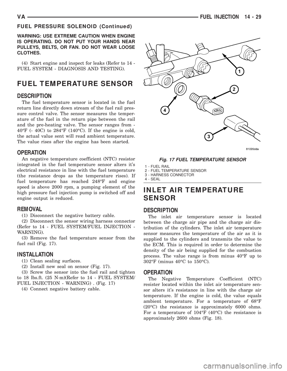
(3) Remove the fuel temperature sensor from the
fuel rail (Fig. 17).
INSTALLATION
(1) Clean sealing surfaces.
(2) Install new seal on sensor (Fig. 17).
(3) Screw the sensor into the fuel rail and tighten
to 18 lbs.ft. (25 N´m)(Refer to 14 - FUEL SYSTEM/
FUEL INJECTION - WARNING) . (Fig. 17)
(4) Connect negative battery cable.
INLET AIR TEMPERATURE
SENSOR
DESCRIPTION
The inlet air temperature sensor is located
between the charge air pipe and the charge air dis-
tribution of the cylinders. The inlet air temperature
sensor measures the temperature of the air as it is
supplied to the cylinders and transmits the value to
the ECM. This is required in order to determine the
density of the air being supplied for the combustion
process. The value range is from minus 40ÉF up to
302ÉF (minus 40ÉC to 150ÉC).
OPERATION
The Negative Temperature Coefficient (NTC)
resister located within the inlet air temperature sen-
sor alters it's resistance in line with the charge air
temperature. If the engine is cold, the value equals
ambient temperature. For a temperature of 68ÉF
(20ÉC) the resistance is approximately 6000 ohms.
For a temperature of 104ÉF (40ÉC) the resistance is
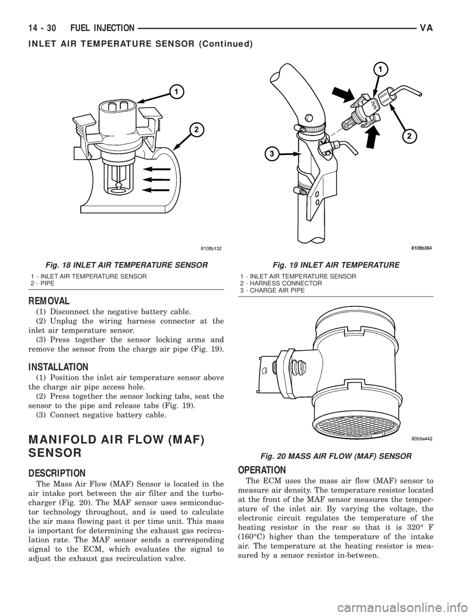
approximately 2600 ohms (Fig. 18).
Fig. 17 FUEL TEMPERATURE SENSOR
1 - FUEL RAIL
2 - FUEL TEMPERATURE SENSOR
3 - HARNESS CONNECTOR
4 - SEAL
VAFUEL INJECTION 14 - 29
FUEL PRESSURE SOLENOID (Continued)
Page 858 of 1232
REMOVAL
(1) Disconnect the negative battery cable.
(2) Unplug the wiring harness connector at the
inlet air temperature sensor.
(3) Press together the sensor locking arms and
remove the sensor from the charge air pipe (Fig. 19).
INSTALLATION
(1) Position the inlet air temperature sensor above
the charge air pipe access hole.
(2) Press together the sensor locking tabs, seat the
sensor to the pipe and release tabs (Fig. 19).
(3) Connect negative battery cable.
MANIFOLD AIR FLOW (MAF)
SENSOR
DESCRIPTION
The Mass Air Flow (MAF) Sensor is located in the
air intake port between the air filter and the turbo-
charger (Fig. 20). The MAF sensor uses semiconduc-
tor technology throughout, and is used to calculate
the air mass flowing past it per time unit. This mass
is important for determining the exhaust gas recircu-
lation rate. The MAF sensor sends a corresponding
signal to the ECM, which evaluates the signal to
adjust the exhaust gas recirculation valve.
OPERATION
The ECM uses the mass air flow (MAF) sensor to
measure air density. The temperature resistor located
at the front of the MAF sensor measures the temper-
ature of the inlet air. By varying the voltage, the
electronic circuit regulates the temperature of the
heating resistor in the rear so that it is 320É F
(160ÉC) higher than the temperature of the intake
air. The temperature at the heating resistor is mea-
sured by a sensor resistor in-between.
Fig. 18 INLET AIR TEMPERATURE SENSOR
1 - INLET AIR TEMPERATURE SENSOR
2 - PIPE
Fig. 19 INLET AIR TEMPERATURE
1 - INLET AIR TEMPERATURE SENSOR
2 - HARNESS CONNECTOR
3 - CHARGE AIR PIPE
Fig. 20 MASS AIR FLOW (MAF) SENSOR
14 - 30 FUEL INJECTIONVA
INLET AIR TEMPERATURE SENSOR (Continued)