2005 MERCEDES-BENZ SPRINTER heating
[x] Cancel search: heatingPage 1133 of 1232
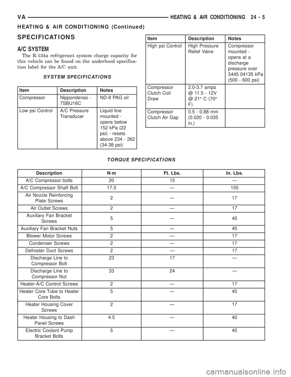
SPECIFICATIONS
A/C SYSTEM
The R-134a refrigerant system charge capacity for
this vehicle can be found on the underhood specifica-
tion label for the A/C unit.
SYSTEM SPECIFICATIONS
Item Description Notes
Compressor Nippondenso -
7SBU16CND-8 PAG oil
Low psi Control A/C Pressure
TransducerLiquid line
mounted -
opens below
152 kPa (22
psi) - resets
above 234 - 262
(34-38 psi)
Item Description Notes
High psi Control High Pressure
Relief ValveCompressor
mounted -
opens at a
discharge
pressure over
3445 04135 kPa
(500 - 600 psi)
Compressor
Clutch Coil
Draw2.0-3.7 amps
@ 11.5 - 12V
@ 21É C (70É
F)
Compressor
Clutch Air Gap0.5 - 0.88 mm
(0.020 - 0.035
in.)
TORQUE SPECIFICATIONS
Description N´m Ft. Lbs. In. Lbs.
A/C Compressor bolts 20 15 Ð
A/C Compressor Shaft Bolt 17.5 Ð 155
Air Nozzle Reinforcing
Plate Screws2Ð 17
Air Outlet Screws 2 Ð 17
Auxiliary Fan Bracket
Screws5Ð 45
Auxiliary Fan Bracket Nuts 5 Ð 45
Blower Motor Screws 2 Ð 17
Condenser Screws 2 Ð 17
Defroster Duct Screws 2 Ð 17
Discharge Line to
Compressor Bolt23 17 Ð
Discharge Line to
Compressor Nut33 24 Ð
Heater-A/C Control Screws 2 Ð 17
Heater Core Tube to Heater
Core Bolts5Ð 45
Heater Housing Cover
Screws2Ð 17
Heater Housing to Dash
Panel Screws4.5 Ð 40
Electric Coolant Pump
Bracket Bolts5Ð 45
VAHEATING & AIR CONDITIONING 24 - 5
HEATING & AIR CONDITIONING (Continued)
Page 1134 of 1232
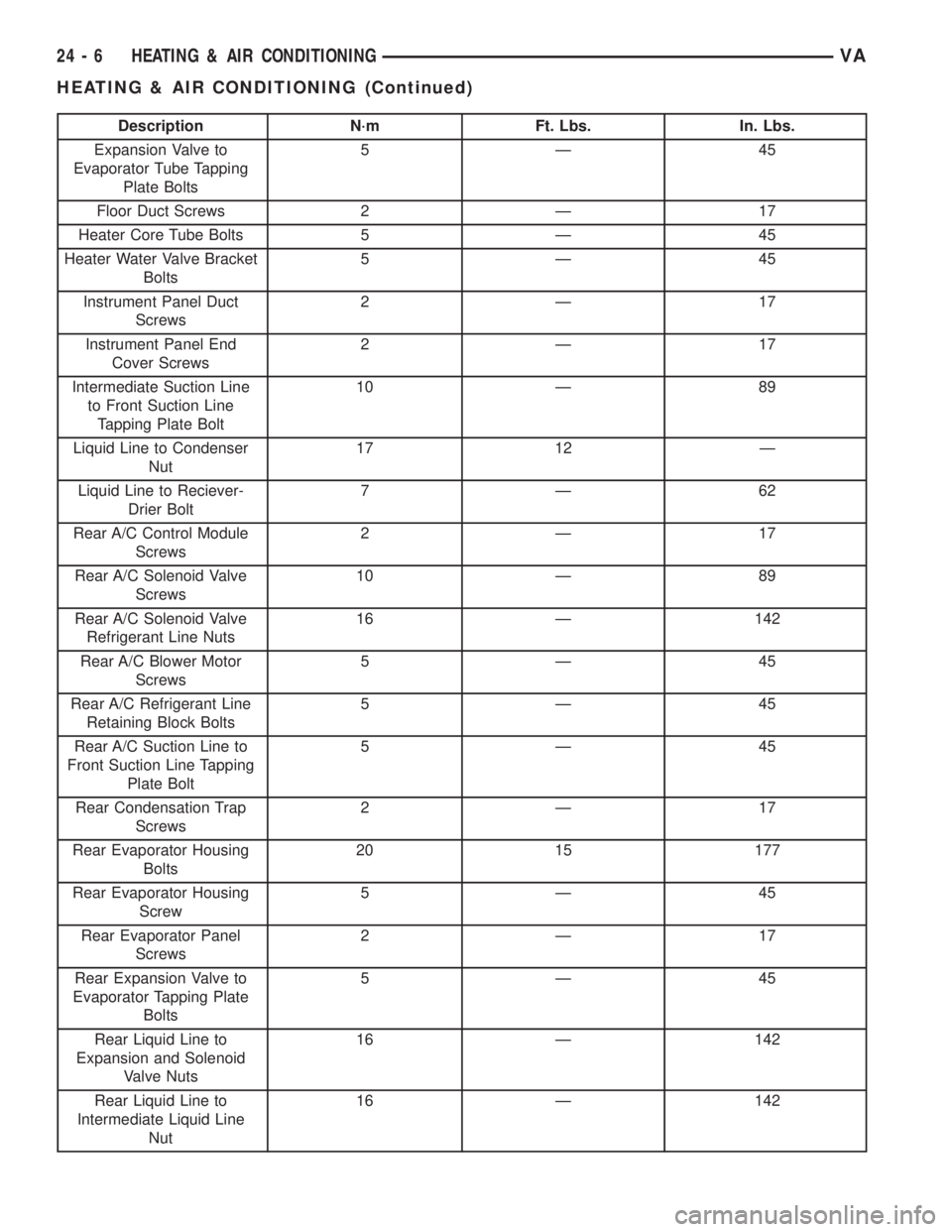
Description N´m Ft. Lbs. In. Lbs.
Expansion Valve to
Evaporator Tube Tapping
Plate Bolts5Ð 45
Floor Duct Screws 2 Ð 17
Heater Core Tube Bolts 5 Ð 45
Heater Water Valve Bracket
Bolts5Ð 45
Instrument Panel Duct
Screws2Ð 17
Instrument Panel End
Cover Screws2Ð 17
Intermediate Suction Line
to Front Suction Line
Tapping Plate Bolt10 Ð 89
Liquid Line to Condenser
Nut17 12 Ð
Liquid Line to Reciever-
Drier Bolt7Ð 62
Rear A/C Control Module
Screws2Ð 17
Rear A/C Solenoid Valve
Screws10 Ð 89
Rear A/C Solenoid Valve
Refrigerant Line Nuts16 Ð 142
Rear A/C Blower Motor
Screws5Ð 45
Rear A/C Refrigerant Line
Retaining Block Bolts5Ð 45
Rear A/C Suction Line to
Front Suction Line Tapping
Plate Bolt5Ð 45
Rear Condensation Trap
Screws2Ð 17
Rear Evaporator Housing
Bolts20 15 177
Rear Evaporator Housing
Screw5Ð 45
Rear Evaporator Panel
Screws2Ð 17
Rear Expansion Valve to
Evaporator Tapping Plate
Bolts5Ð 45
Rear Liquid Line to
Expansion and Solenoid
Valve Nuts16 Ð 142
Rear Liquid Line to
Intermediate Liquid Line
Nut16 Ð 142
24 - 6 HEATING & AIR CONDITIONINGVA
HEATING & AIR CONDITIONING (Continued)
Page 1135 of 1232
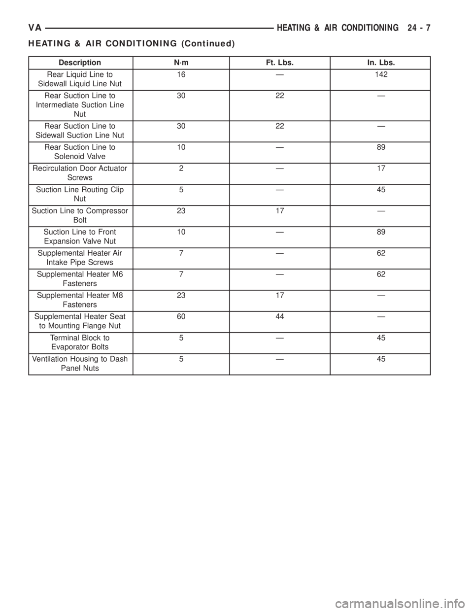
Description N´m Ft. Lbs. In. Lbs.
Rear Liquid Line to
Sidewall Liquid Line Nut16 Ð 142
Rear Suction Line to
Intermediate Suction Line
Nut30 22 Ð
Rear Suction Line to
Sidewall Suction Line Nut30 22 Ð
Rear Suction Line to
Solenoid Valve10 Ð 89
Recirculation Door Actuator
Screws2Ð 17
Suction Line Routing Clip
Nut5Ð 45
Suction Line to Compressor
Bolt23 17 Ð
Suction Line to Front
Expansion Valve Nut10 Ð 89
Supplemental Heater Air
Intake Pipe Screws7Ð 62
Supplemental Heater M6
Fasteners7Ð 62
Supplemental Heater M8
Fasteners23 17 Ð
Supplemental Heater Seat
to Mounting Flange Nut60 44 Ð
Terminal Block to
Evaporator Bolts5Ð 45
Ventilation Housing to Dash
Panel Nuts5Ð 45
VAHEATING & AIR CONDITIONING 24 - 7
HEATING & AIR CONDITIONING (Continued)
Page 1139 of 1232
(2) Examine the friction surfaces of the clutch pul-
ley and the clutch plate for oil contamination. If the
friction surfaces are oily, the clutch pulley and clutch
plate should be replaced. Also inspect the shaft and
nose area of the compressor for oil. Remove the felt
packing from around the compressor shaft in the
compressor front cover. If the felt is saturated with
oil, the compressor front shaft seal is leaking and the
compressor will also have to be replaced.
(3) Check the clutch pulley bearing for roughness
or excessive leakage of grease. Replace the clutch
pulley and clutch plate if the bearing is faulty.
INSTALLATION
(1) Align the dowel pin on the back of the clutch
field coil with the hole in the compressor front cover,
and position the clutch coil onto the compressor. Be
certain that the cluch coil wire harness leads are
properly oriented and routed so that they are not
pinched between the compressor front cover and the
clutch coil.
NOTE: A new snap ring must be used to secure the
clutch coil to the compressor. The bevel side of the
snap ring must face outward.
(2) Using snap ring pliers (Special Tool C-4574 or
equivalent), install the external snap ring that
secures the clutch coil to the front cover of the com-
pressor. The bevel side of the snap ring must be fac-
ing outward and both snap ring eyelets must be
oriented to the right or left of the clutch coil dowel
pin on the compressor. Be certain that the snap ring
is fully and properly seated in the groove.
CAUTION: If the snap ring is not fully seated in the
groove it will vibrate out, resulting in a clutch fail-
ure and severe damage to the compressor front
cover.
(3) Install and tighten the screw that secures the
clutch coil wire harness connector bracket and
ground clip to the top of the compressor housing.
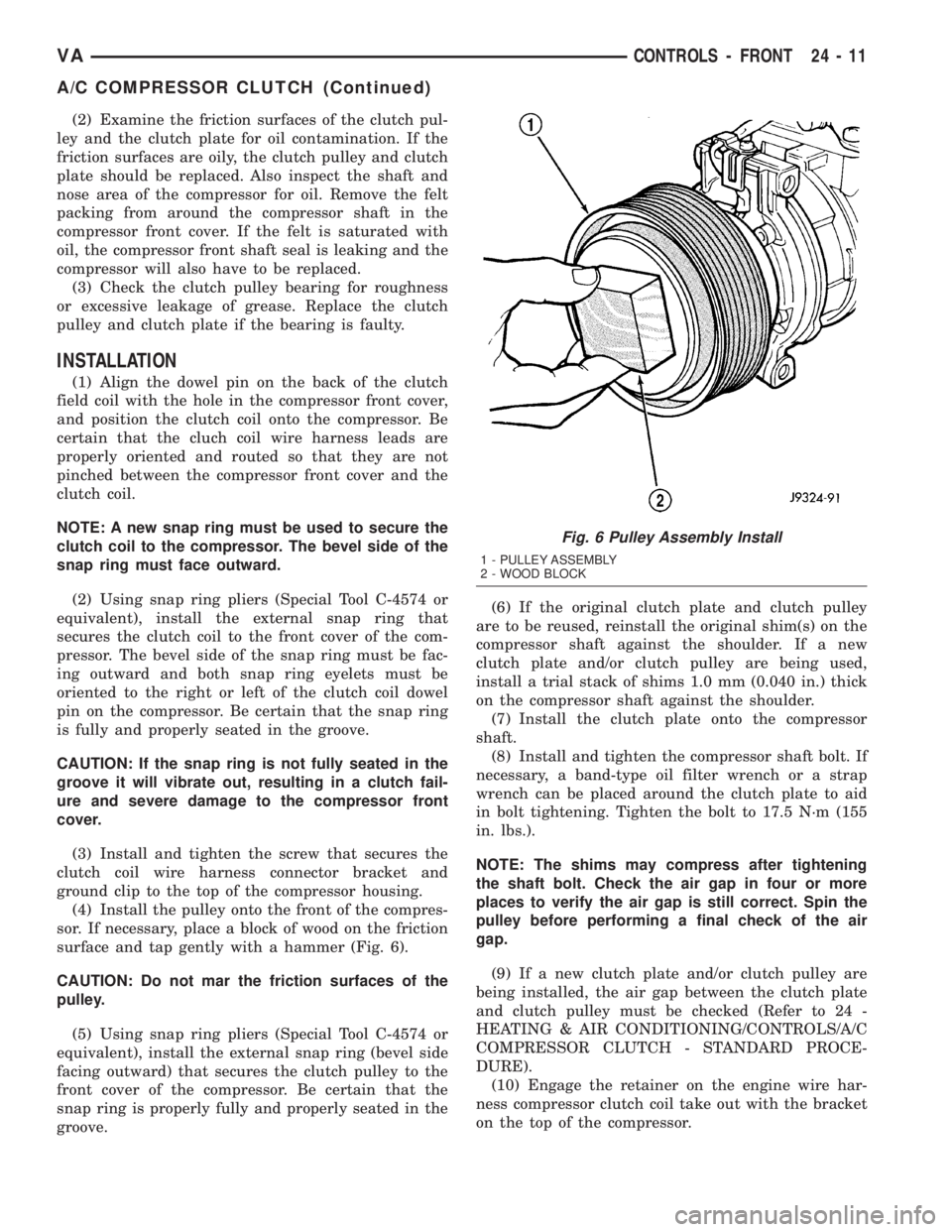
(4) Install the pulley onto the front of the compres-
sor. If necessary, place a block of wood on the friction
surface and tap gently with a hammer (Fig. 6).
CAUTION: Do not mar the friction surfaces of the
pulley.
(5) Using snap ring pliers (Special Tool C-4574 or
equivalent), install the external snap ring (bevel side
facing outward) that secures the clutch pulley to the
front cover of the compressor. Be certain that the
snap ring is properly fully and properly seated in the
groove.(6) If the original clutch plate and clutch pulley
are to be reused, reinstall the original shim(s) on the
compressor shaft against the shoulder. If a new
clutch plate and/or clutch pulley are being used,
install a trial stack of shims 1.0 mm (0.040 in.) thick
on the compressor shaft against the shoulder.
(7) Install the clutch plate onto the compressor
shaft.
(8) Install and tighten the compressor shaft bolt. If
necessary, a band-type oil filter wrench or a strap
wrench can be placed around the clutch plate to aid
in bolt tightening. Tighten the bolt to 17.5 N´m (155
in. lbs.).
NOTE: The shims may compress after tightening
the shaft bolt. Check the air gap in four or more
places to verify the air gap is still correct. Spin the
pulley before performing a final check of the air
gap.
(9) If a new clutch plate and/or clutch pulley are
being installed, the air gap between the clutch plate
and clutch pulley must be checked (Refer to 24 -
HEATING & AIR CONDITIONING/CONTROLS/A/C
COMPRESSOR CLUTCH - STANDARD PROCE-
DURE).
(10) Engage the retainer on the engine wire har-
ness compressor clutch coil take out with the bracket
on the top of the compressor.
Fig. 6 Pulley Assembly Install
1 - PULLEY ASSEMBLY
2 - WOOD BLOCK
VACONTROLS - FRONT 24 - 11
A/C COMPRESSOR CLUTCH (Continued)
Page 1140 of 1232
(11) Reconnect the engine wire harness connector
for the compressor clutch coil to the coil wire harness
connector on the top of the compressor.
(12) Reinstall the serpentine accessory drive belt
(Refer to 7 - COOLING/ACCESSORY DRIVE/DRIVE
BELTS - INSTALLATION).
(13) Reconnect the battery negative cable.
(14) If a new clutch plate and/or clutch pulley are
being installed, the new clutch components must be
burnished (Refer to 24 - HEATING & AIR CONDI-
TIONING/CONTROLS/A/C COMPRESSOR CLUTCH
- STANDARD PROCEDURE).
A/C COMPRESSOR CLUTCH
COIL
DIAGNOSIS AND TESTING - COMPRESSOR
CLUTCH COIL
The air conditioning compressor clutch coil electri-
cal circuit is controlled by the ATC control module
which is integral to the heater-A/C control. Begin
testing of a suspected compressor clutch coil problem
by performing the ATC Function Test using the
DRBIIItscan tool.
A/C HEATER CONTROL
DESCRIPTION
This ATC system uses a combination of electrical
and mechanical controls. These controls provide the
vehicle operator with a number of setting options to
help control the climate and comfort within the vehi-
cle.
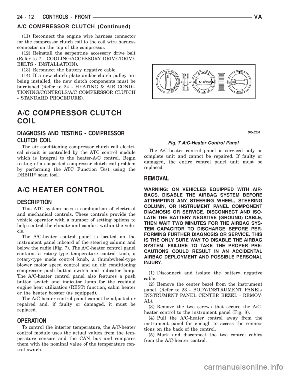
The A/C-heater control panel is located on the
instrument panel inboard of the steering column and
below the radio (Fig. 7). The A/C-heater control panel
contains a rotary-type temperature control knob, a
rotary-type mode control knob, a thumbwheel-type
blower motor speed control and an air conditioning
compressor push button switch and indicator lamp.
The A/C-heater control panel also features a push
button switch and indicator lamp for the residual
engine heat utilization (REST) function, cabin heater
or the heater booster (as equipped).
The A/C-heater control panel cannot be adjusted or
repaired and, if faulty or damaged, it must be
replaced.
OPERATION
To control the interior temperature, the A/C-heater
control module uses the actual values from the tem-
perature sensors and the CAN bus and compares
them with the nominal value of the temperature con-
trol switch.The A/C-heater control panel is serviced only as
complete unit and cannot be repaired. If faulty or
damaged, the entire control panel unit must be
replaced.
REMOVAL
WARNING: ON VEHICLES EQUIPPED WITH AIR-
BAGS, DISABLE THE AIRBAG SYSTEM BEFORE
ATTEMPTING ANY STEERING WHEEL, STEERING
COLUMN, OR INSTRUMENT PANEL COMPONENT
DIAGNOSIS OR SERVICE. DISCONNECT AND ISO-
LATE THE BATTERY NEGATIVE (GROUND) CABLE,
THEN WAIT TWO MINUTES FOR THE AIRBAG SYS-
TEM CAPACITOR TO DISCHARGE BEFORE PER-
FORMING FURTHER DIAGNOSIS OR SERVICE. THIS
IS THE ONLY SURE WAY TO DISABLE THE AIRBAG
SYSTEM. FAILURE TO TAKE THE PROPER PRE-
CAUTIONS COULD RESULT IN AN ACCIDENTAL
AIRBAG DEPLOYMENT AND POSSIBLE PERSONAL
INJURY.
(1) Disconnect and isolate the battery negative
cable.
(2) Remove the center bezel from the instrument
panel. (Refer to 23 - BODY/INSTRUMENT PANEL/
INSTRUMENT PANEL CENTER BEZEL - REMOV-
AL).
(3) Remove the two screws that secure the A/C-
heater control to the instrument panel (Fig. 8).
(4) Pull the A/C-heater control away from the
instrument panel far enough to access the connec-
tions on the back of the control.
(5) Mark and disconnect the two control cables
from the A/C-heater control.
Fig. 7 A/C-Heater Control Panel
24 - 12 CONTROLS - FRONTVA
A/C COMPRESSOR CLUTCH (Continued)
Page 1142 of 1232
A/C PRESSURE TRANSDUCER VOLTAGE
Voltage Possible Cause
0.0 1. No transducer supply voltage from ATC control module.
2. Shorted transducer circuit.
3. Faulty transducer.
0.150 to 0.450 1. Ambient temperature below 10É C (50É F).
2. Low refrigerant system pressure.
0.451 to 4.519 1. Normal refrigerant system pressure.
4.520 to 4.850 1. High refrigerant system pressure.
5.0 1. Open transducer circuit.
2. Faulty transducer.
REMOVAL
WARNING: REFER TO THE APPLICABLE WARN-
INGS AND CAUTIONS FOR THIS SYSTEM BEFORE
PERFORMING THE FOLLOWING OPERATION (Refer
to 24 - HEATING & AIR CONDITIONING/PLUMBING -
WARNING) and (Refer to 24 - HEATING & AIR CON-
DITIONING/PLUMBING - CAUTION).
(1) Recover the refrigerant from the refrigerant
system (Refer to 24 - HEATING & AIR CONDITION-
ING/PLUMBING - STANDARD PROCEDURE).
(2) Disconnect and isolate the battery negative
cable.
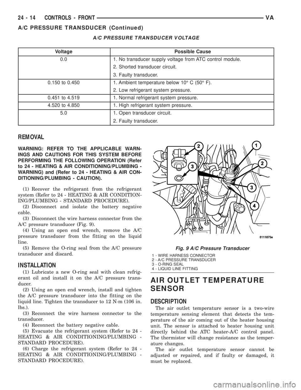
(3) Disconnect the wire harness connector from the
A/C pressure transducer (Fig. 9).
(4) Using an open end wrench, remove the A/C
pressure transducer from the fitting on the liquid
line.
(5) Remove the O-ring seal from the A/C pressure
transducer and discard.
INSTALLATION
(1) Lubricate a new O-ring seal with clean refrig-
erant oil and install it on the A/C pressure trans-
ducer.
(2) Using an open end wrench, install and tighten
the A/C pressure transducer into the fitting on the
liquid line. Tighten the transducer to 12 N´m (106 in.
lbs.).
(3) Reconnect the wire harness connector to the
transducer.
(4) Reconnect the battery negative cable.
(5) Evacuate the refrigerant system (Refer to 24 -
HEATING & AIR CONDITIONING/PLUMBING -
STANDARD PROCEDURE).
(6) Charge the refrigerant system (Refer to 24 -
HEATING & AIR CONDITIONING/PLUMBING -
STANDARD PROCEDURE).
AIR OUTLET TEMPERATURE
SENSOR
DESCRIPTION
The air outlet temperature sensor is a two-wire
temperature sensing element that detects the tem-
perature of the air coming out of the heater housing
unit. The sensor is attached to heater housing unit
directly behind the ATC heater-A/C control panel.
The thermistor will change resistance as the temper-
ature changes.
The air outlet temperature sensor cannot be
adjusted or repaired, and if faulty or damaged, it
must be replaced.
Fig. 9 A/C Pressure Transducer
1 - WIRE HARNESS CONNECTOR
2 - A/C PRESSURE TRANSDUCER
3 - O-RING SEAL
4 - LIQUID LINE FITTING
24 - 14 CONTROLS - FRONTVA
A/C PRESSURE TRANSDUCER (Continued)
Page 1143 of 1232
OPERATION
The air outlet temperature sensor monitors the
temperature of the air coming out of the heater hous-
ing unit. The sensor will change its internal resis-
tance in response to the temperatures it monitors.
The ATC control module is connected to the sensor
through a sensor ground circuit and a sensor signal
circuit. As the air temperature increases, the resis-
tance of the sensor decreases and the voltage moni-
tored by the module decreases. The module uses this
monitored voltage reading to an indication of the out-
let air temperature. The ATC control module makes
adjustments to maintain the requested interior tem-
perature by cycling both the A/C compressor and
solenoid heater valve on and off.
The air outlet temperature sensor is diagnosed by
performing the ATC Function Test using the DRBIIIt
scan tool. Refer to Body Diagnostic Procedures.
REMOVAL
(1) Disconnect and isolate the battery negative
cable.
(2) Remove the heater-A/C control from the instru-
ment panel (Refer to 24 - HEATING & AIR CONDI-
TIONING/CONTROLS/A/C HEATER CONTROL -
REMOVAL).
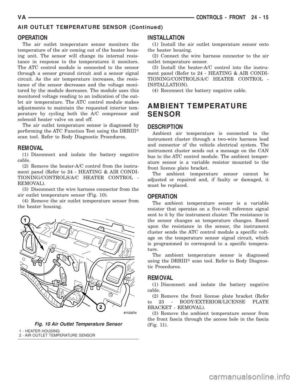
(3) Disconnect the wire harness connector from the
air outlet temperature sensor (Fig. 10).
(4) Remove the air outlet temperature sensor from
the heater housing.
INSTALLATION
(1) Install the air outlet temperature sensor onto
the heater housing.
(2) Connect the wire harness connector to the air
outlet temperature sensor.
(3) Install the heater-A/C control into the instru-
ment panel (Refer to 24 - HEATING & AIR CONDI-
TIONING/CONTROLS/A/C HEATER CONTROL -
INSTALLATION).
(4) Reconnect the battery negative cable.
AMBIENT TEMPERATURE
SENSOR
DESCRIPTION
Ambient air temperature is connected to the
instrument cluster through a two-wire harness lead
and connector of the vehicle electrical system. The
instrument cluster sends out a message on the CAN
bus to the ATC control module. The ambient temper-
ature sensor is a variable resistor mounted to the
front licence plate bracket.
The ambient temperature sensor cannot be
adjusted or repaired and, if faulty or damaged, it
must be replaced.
OPERATION
The ambient temperature sensor is a variable
resistor that operates on a five-volt reference signal
sent to it by the instrument cluster. The resistance in
the sensor changes as temperature changes. Based
upon the resistance in the sensor, the instrument
cluster sends the ATC control module a specific volt-
age on the temperature sensor signal circuit, which
is programmed to correspond to a specific tempera-
ture.
The ambient temperature sensor is diagnosed
using the DRBIIItscan tool. Refer to Body Diagnos-
tic Procedures.
REMOVAL
(1) Disconnect and isolate the battery negative
cable.
(2) Remove the front license plate bracket (Refer
to 23 - BODY/EXTERIOR/LICENSE PLATE
BRACKET - REMOVAL).
(3) Remove the ambient temperature sensor from
the front fascia through the access hole in the fascia
(Fig. 11).
Fig. 10 Air Outlet Temperature Sensor
1 - HEATER HOUSING
2 - AIR OUTLET TEMPERATURE SENSOR
VACONTROLS - FRONT 24 - 15
AIR OUTLET TEMPERATURE SENSOR (Continued)
Page 1145 of 1232
INSTALLATION
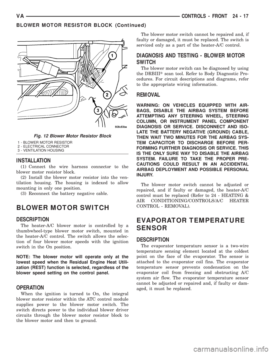
(1) Connect the wire harness connector to the
blower motor resistor block.
(2) Install the blower motor resistor into the ven-
tilation housing. The housing is indexed to allow
mounting in only one position.
(3) Reconnect the battery negative cable.
BLOWER MOTOR SWITCH
DESCRIPTION
The heater-A/C blower motor is controlled by a
thumbwheel-type blower motor switch, mounted in
the heater-A/C control. The switch allows the selec-
tion of four blower motor speeds with the ignition
switch in the On position.
NOTE: The blower motor will operate only at the
lowest speed when the Residual Engine Heat Utili-
zation (REST) function is selected, regardless of the
blower speed setting on the control panel.
OPERATION
When the ignition is turned to On, the integral
blower motor resistor within the ATC control module
supplies power to the blower motor switch. The
switch directs power to the individual blower driver
circuits through the blower motor resistor block to
the blower motor and then to ground.The blower motor switch cannot be repaired and, if
faulty or damaged, it must be replaced. The switch is
serviced only as a part of the heater-A/C control.
DIAGNOSIS AND TESTING - BLOWER MOTOR
SWITCH
The blower motor switch can be diagnosed by using
the DRBIIItscan tool. Refer to Body Diagnostic Pro-
cedures. For circuit descriptions and diagrams, refer
to the appropriate wiring information.
REMOVAL
WARNING: ON VEHICLES EQUIPPED WITH AIR-
BAGS, DISABLE THE AIRBAG SYSTEM BEFORE
ATTEMPTING ANY STEERING WHEEL, STEERING
COLUMN, OR INSTRUMENT PANEL COMPONENT
DIAGNOSIS OR SERVICE. DISCONNECT AND ISO-
LATE THE BATTERY NEGATIVE (GROUND) CABLE,
THEN WAIT TWO MINUTES FOR THE AIRBAG SYS-
TEM CAPACITOR TO DISCHARGE BEFORE PER-
FORMING FURTHER DIAGNOSIS OR SERVICE. THIS
IS THE ONLY SURE WAY TO DISABLE THE AIRBAG
SYSTEM. FAILURE TO TAKE THE PROPER PRE-
CAUTIONS COULD RESULT IN AN ACCIDENTAL
AIRBAG DEPLOYMENT AND POSSIBLE PERSONAL
INJURY.
The blower motor switch cannot be adjusted or
repaired, and if faulty or damaged, the heater-A/C
control must be replaced (Refer to 24 - HEATING &
AIR CONDITIONING/CONTROLS/A/C HEATER
CONTROL - REMOVAL).
EVAPORATOR TEMPERATURE
SENSOR
DESCRIPTION
The evaporator temperature sensor is a two-wire
temperature sensing element located at the coldest
point on the face of the evaporator. The sensor is
attached to the evaporator coil fins. The evaporator
temperature sensor prevents condensation on the
evaporator coil from freezing and obstructing A/C
system air flow. The evaporator temperature sensor
cannot be adjusted or repaired and, if faulty or dam-
aged, it must be replaced.
Fig. 12 Blower Motor Resistor Block
1 - BLOWER MOTOR RESISTOR
2 - ELECTRICAL CONNECTOR
3 - VENTILATION HOUSING
VACONTROLS - FRONT 24 - 17
BLOWER MOTOR RESISTOR BLOCK (Continued)