2005 MERCEDES-BENZ SPRINTER charging
[x] Cancel search: chargingPage 147 of 1232
(4) Connect field terminal connector at rear of gen-
erator.
(5) Install battery output cable and nut to B+ ter-
minal at top of generator. Refer to Torque Specifica-
tions.
(6) Install protective plastic cover to B+ stud at
top of generator.
(7) Lower vehicle.
CAUTION: Never force a belt over a pulley rim
using a screwdriver. The synthetic fiber of the belt
can be damaged.
CAUTION: When installing a serpentine accessory
drive belt, the belt MUST be routed correctly. The
water pump will be rotating in the wrong direction if
the belt is installed incorrectly, causing the engine
to overheat. Refer to belt routing label in engine
compartment, or refer to Belt Schematics in Cooling
System.
(8) Install generator drive belt. Refer to Cooling
System for procedure.
(9) Connect negative battery cable.
(10) Check charging system for proper operation.
GENERATOR DECOUPLER
PULLEY
DESCRIPTION
The generator decoupler is used only with
certain engines.The decoupler is used in place of
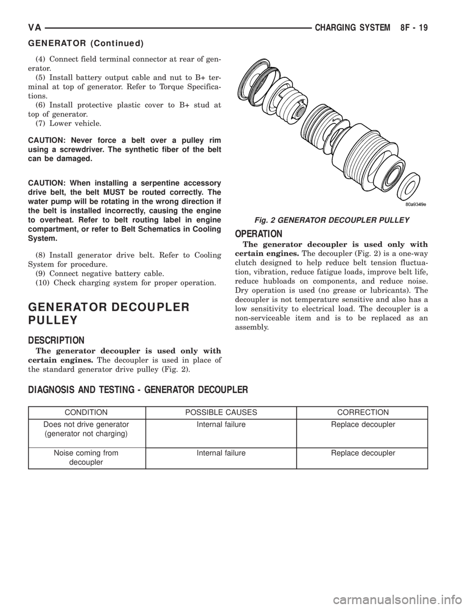
the standard generator drive pulley (Fig. 2).
OPERATION
The generator decoupler is used only with
certain engines.The decoupler (Fig. 2) is a one-way
clutch designed to help reduce belt tension fluctua-
tion, vibration, reduce fatigue loads, improve belt life,
reduce hubloads on components, and reduce noise.
Dry operation is used (no grease or lubricants). The
decoupler is not temperature sensitive and also has a
low sensitivity to electrical load. The decoupler is a
non-serviceable item and is to be replaced as an
assembly.
DIAGNOSIS AND TESTING - GENERATOR DECOUPLER
CONDITION POSSIBLE CAUSES CORRECTION
Does not drive generator
(generator not charging)Internal failure Replace decoupler
Noise coming from
decouplerInternal failure Replace decoupler
Fig. 2 GENERATOR DECOUPLER PULLEY
VACHARGING SYSTEM 8F - 19
GENERATOR (Continued)
Page 148 of 1232
REMOVAL
The generator decoupler is used only with
certain engines.
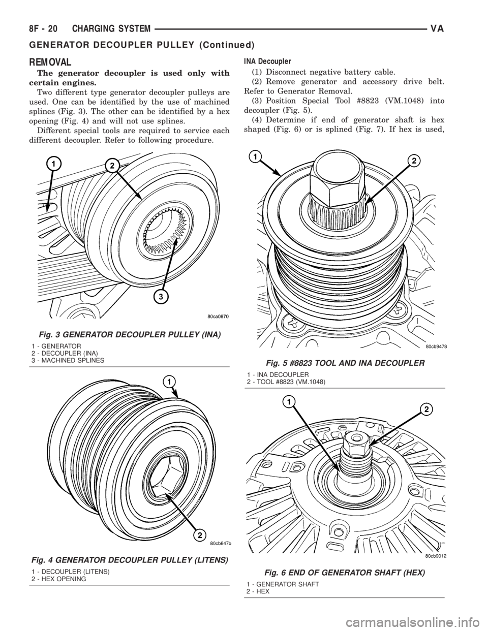
Two different type generator decoupler pulleys are
used. One can be identified by the use of machined
splines (Fig. 3). The other can be identified by a hex
opening (Fig. 4) and will not use splines.
Different special tools are required to service each
different decoupler. Refer to following procedure.INA Decoupler
(1) Disconnect negative battery cable.
(2) Remove generator and accessory drive belt.
Refer to Generator Removal.
(3) Position Special Tool #8823 (VM.1048) into
decoupler (Fig. 5).
(4) Determine if end of generator shaft is hex
shaped (Fig. 6) or is splined (Fig. 7). If hex is used,
Fig. 5 #8823 TOOL AND INA DECOUPLER
1 - INA DECOUPLER
2 - TOOL #8823 (VM.1048)
Fig. 6 END OF GENERATOR SHAFT (HEX)
1 - GENERATOR SHAFT
2 - HEX
Fig. 3 GENERATOR DECOUPLER PULLEY (INA)
1 - GENERATOR
2 - DECOUPLER (INA)
3 - MACHINED SPLINES
Fig. 4 GENERATOR DECOUPLER PULLEY (LITENS)
1 - DECOUPLER (LITENS)
2 - HEX OPENING
8F - 20 CHARGING SYSTEMVA
GENERATOR DECOUPLER PULLEY (Continued)
Page 149 of 1232
insert a 10MM deep socket into tool #8823 (VM.1048)
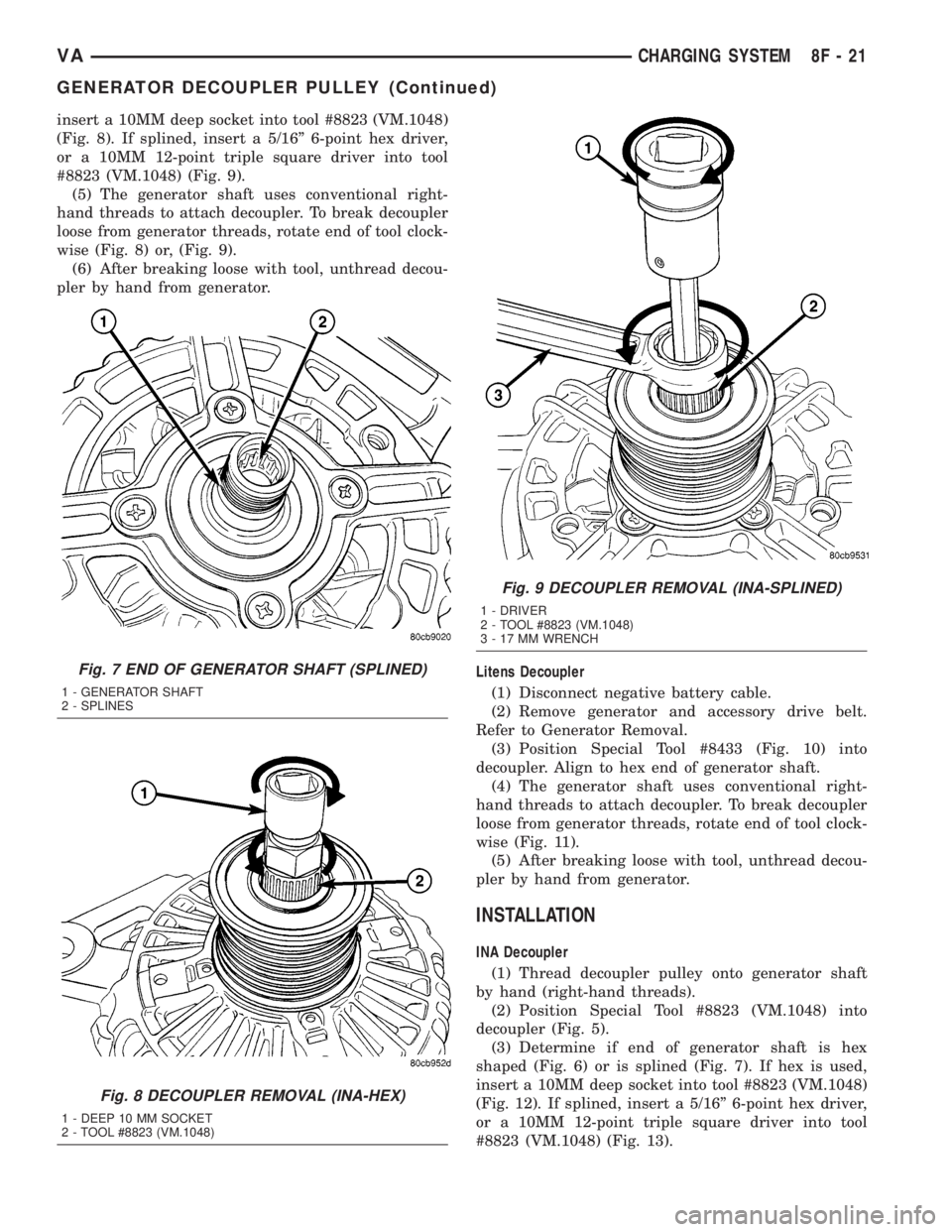
(Fig. 8). If splined, insert a 5/16º 6-point hex driver,
or a 10MM 12-point triple square driver into tool
#8823 (VM.1048) (Fig. 9).
(5) The generator shaft uses conventional right-
hand threads to attach decoupler. To break decoupler
loose from generator threads, rotate end of tool clock-
wise (Fig. 8) or, (Fig. 9).
(6) After breaking loose with tool, unthread decou-
pler by hand from generator.
Litens Decoupler
(1) Disconnect negative battery cable.
(2) Remove generator and accessory drive belt.
Refer to Generator Removal.
(3) Position Special Tool #8433 (Fig. 10) into
decoupler. Align to hex end of generator shaft.
(4) The generator shaft uses conventional right-
hand threads to attach decoupler. To break decoupler
loose from generator threads, rotate end of tool clock-
wise (Fig. 11).
(5) After breaking loose with tool, unthread decou-
pler by hand from generator.
INSTALLATION
INA Decoupler
(1) Thread decoupler pulley onto generator shaft
by hand (right-hand threads).
(2) Position Special Tool #8823 (VM.1048) into
decoupler (Fig. 5).
(3) Determine if end of generator shaft is hex
shaped (Fig. 6) or is splined (Fig. 7). If hex is used,
insert a 10MM deep socket into tool #8823 (VM.1048)
(Fig. 12). If splined, insert a 5/16º 6-point hex driver,
or a 10MM 12-point triple square driver into tool
#8823 (VM.1048) (Fig. 13).
Fig. 7 END OF GENERATOR SHAFT (SPLINED)
1 - GENERATOR SHAFT
2 - SPLINES
Fig. 8 DECOUPLER REMOVAL (INA-HEX)
1 - DEEP 10 MM SOCKET
2 - TOOL #8823 (VM.1048)
Fig. 9 DECOUPLER REMOVAL (INA-SPLINED)
1 - DRIVER
2 - TOOL #8823 (VM.1048)
3 - 17 MM WRENCH
VACHARGING SYSTEM 8F - 21
GENERATOR DECOUPLER PULLEY (Continued)
Page 150 of 1232
(4)Do not use an adjustable, ratcheting ªclick
typeº torque wrench. Most ªclick typeº
wrenches will only allow torque to be applied
in a clockwise rotation. Use a dial-type or
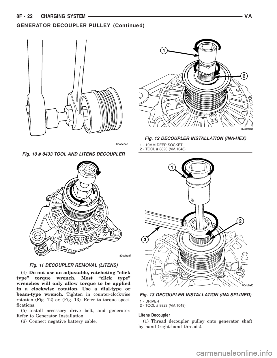
beam-type wrench.Tighten in counter-clockwise
rotation (Fig. 12) or, (Fig. 13). Refer to torque speci-
fications.
(5) Install accessory drive belt, and generator.
Refer to Generator Installation.
(6) Connect negative battery cable.Litens Decoupler
(1) Thread decoupler pulley onto generator shaft
by hand (right-hand threads).
Fig. 10 # 8433 TOOL AND LITENS DECOUPLER
Fig. 11 DECOUPLER REMOVAL (LITENS)
Fig. 12 DECOUPLER INSTALLATION (INA-HEX)
1 - 10MM DEEP SOCKET
2 - TOOL # 8823 (VM.1048)
Fig. 13 DECOUPLER INSTALLATION (INA SPLINED)
1 - DRIVER
2 - TOOL # 8823 (VM.1048)
8F - 22 CHARGING SYSTEMVA
GENERATOR DECOUPLER PULLEY (Continued)
Page 151 of 1232
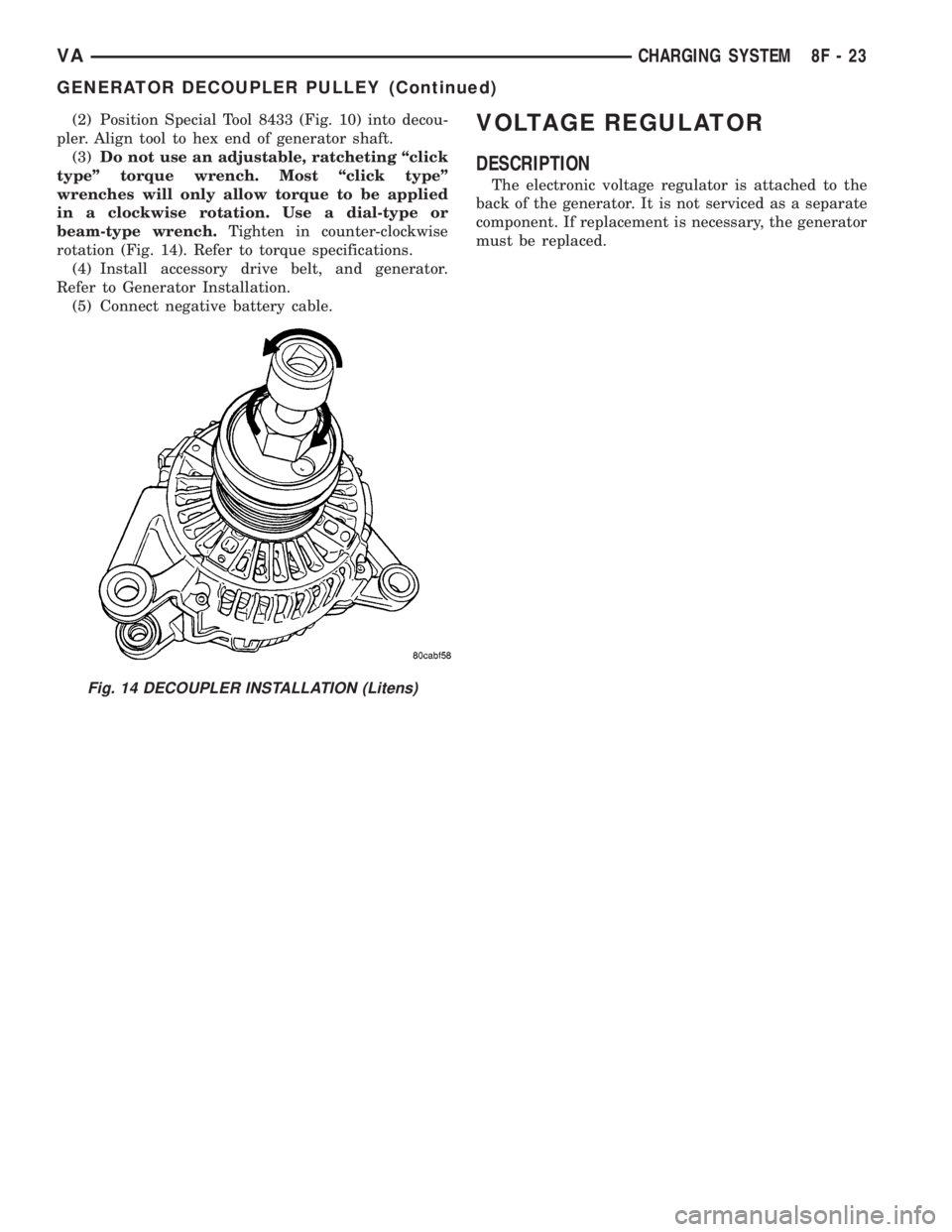
(2) Position Special Tool 8433 (Fig. 10) into decou-
pler. Align tool to hex end of generator shaft.
(3)Do not use an adjustable, ratcheting ªclick
typeº torque wrench. Most ªclick typeº
wrenches will only allow torque to be applied
in a clockwise rotation. Use a dial-type or
beam-type wrench.Tighten in counter-clockwise
rotation (Fig. 14). Refer to torque specifications.
(4) Install accessory drive belt, and generator.
Refer to Generator Installation.
(5) Connect negative battery cable.VOLTAGE REGULATOR
DESCRIPTION
The electronic voltage regulator is attached to the
back of the generator. It is not serviced as a separate
component. If replacement is necessary, the generator
must be replaced.
Fig. 14 DECOUPLER INSTALLATION (Litens)
VACHARGING SYSTEM 8F - 23
GENERATOR DECOUPLER PULLEY (Continued)
Page 152 of 1232
STARTING SYSTEM
TABLE OF CONTENTS
page page
STARTING SYSTEM
DESCRIPTION.........................24
OPERATION...........................24
DIAGNOSIS AND TESTING - STARTING
SYSTEM............................25
SPECIFICATIONS
TORQUE - STARTER - DIESEL...........29
SPECIFICATIONS - STARTER MOTOR -
DIESEL.............................29STARTER MOTOR
DIAGNOSIS AND TESTING - STARTER
MOTOR .............................29
REMOVAL.............................30
INSTALLATION.........................31
STARTER MOTOR RELAY
DESCRIPTION.........................31
REMOVAL.............................31
INSTALLATION.........................32
STARTING SYSTEM
DESCRIPTION
The starting system consists of:
²Starter relay
²Starter motor (including an integral starter sole-
noid)
Other components to be considered as part of start-
ing system are:
²Battery
²Battery cables
²Ignition switch and key lock cylinder
²Park/neutral position switch (automatic trans-
mission)
²Wire harnesses and connections.
The Battery, Starting, and Charging systems oper-
ate in conjunction with one another, and must be
tested as a complete system. For correct operation of
starting/charging systems, all components used in
these 3 systems must perform within specifications.
When attempting to diagnose any of these systems, it
is important that you keep their interdependency in
mind.
The diagnostic procedures used in each of these
groups include the most basic conventional diagnostic
methods, to the more sophisticated On-Board Diag-
nostics (OBD) built into the Engine Control Module
(ECM). Use of an induction-type milliampere amme-
ter, volt/ohmmeter, battery charger, carbon pile rheo-
stat (load tester), and 12-volt test lamp may be
required.
Certain starting system components are monitored
by the ECM and may produce a Diagnostic Trouble
Code (DTC).
OPERATION
The starting system components form two separate
circuits. A high-amperage feed circuit that feeds thestarter motor high-amperage, and a low-amperage
control circuit that operates on less than 20 amperes.
The high-amperage feed circuit components include
the battery, the battery cables, the contact disc por-
tion of the starter solenoid, and the starter motor
itself. The low-amperage control circuit components
include the ignition switch, the park/neutral position
switch (automatic transmission), the starter relay,
the electromagnetic windings of the starter solenoid,
and the connecting wire harness components.
If the vehicle is equipped with an automatic trans-
mission, battery voltage is supplied through the low-
amperage control circuit to the coil battery terminal
of the starter relay when the ignition switch is
turned to the momentary Start position. The park/
neutral position switch is installed in series between
the starter relay coil ground terminal and ground.
This normally open switch prevents the starter relay
from being energized and the starter motor from
operating unless the automatic transmission gear
selector is in the Neutral or Park positions.
When the starter relay coil is energized, the nor-
mally open relay contacts close. The relay contacts
connect the relay common feed terminal to the relay
normally open terminal. The closed relay contacts
energize the starter solenoid coil windings.
The energized solenoid pull-in coil pulls in the sole-
noid plunger. The solenoid plunger pulls the shift
lever in the starter motor. This engages the starter
overrunning clutch and pinion gear with the starter
ring gear on the manual transmission flywheel or on
the automatic transmission torque converter or
torque converter drive plate.
As the solenoid plunger reaches the end of its
travel, the solenoid contact disc completes the high-
amperage starter feed circuit and energizes the sole-
noid plunger hold-in coil. Current now flows between
the solenoid battery terminal and the starter motor,
energizing the starter.
8F - 24 STARTING SYSTEMVA
Page 153 of 1232
Once the engine starts, the overrunning clutch pro-
tects the starter motor from damage by allowing the
starter pinion gear to spin faster than the pinion
shaft. When the driver releases the ignition switch to
the On position, the starter relay coil is de-energized.
This causes the relay contacts to open. When the
relay contacts open, the starter solenoid plunger
hold-in coil is de-energized.
When the solenoid plunger hold-in coil is de-ener-
gized, the solenoid plunger return spring returns the
plunger to its relaxed position. This causes the con-
tact disc to open the starter feed circuit, and the shiftlever to disengage the overrunning clutch and pinion
gear from the starter ring gear.
DIAGNOSIS AND TESTING - STARTING
SYSTEM
The battery, starting, and charging systems oper-
ate in conjunction with one another, and must be
tested as a complete system. For correct starting/
charging system operation, all of the components
involved in these 3 systems must perform within
specifications.
Starting System Diagnosis
CONDITION POSSIBLE CAUSE CORRECTION
STARTER FAILS TO
OPERATE.1. Battery discharged or
faulty.1. Refer to Battery. Charge or replace battery, if required.
2. Starting circuit wiring
faulty.2. Refer to 8, Wiring Diagrams. Test and repair starter
feed and/or control circuits, if required.
3. Starter relay faulty. 3. Refer to Starter Relay in Diagnosis and Testing.
Replace starter relay if required.
4. Ignition switch faulty. 4. Refer to Ignition Switch and Key Lock Cylinder.
Replace ignition switch if required.
5. Clutch pedal position
switch faulty.5. Refer to Clutch Pedal Position Switch.
6. Park/Neutral position
switch faulty or
misadjusted.6. Refer to Park/Neutral Position Switch. Replace
park/neutral position switch if required.
7. Starter solenoid faulty. 7. Refer to Starter Motor. Replace starter motor assembly
if required.
8. Starter motor faulty. 8. If all other starting system components and circuits test
OK, replace starter motor.
STARTER ENGAGES,
FAILS TO TURN
ENGINE.1. Battery discharged or
faulty.1. Refer to Battery. Charge or replace battery if required.
2. Starting circuit wiring
faulty.2. Refer to 8, Wiring Diagrams. Test and repair starter
feed and/or control circuits if required.
3. Starter motor faulty. 3. If all other starting system components and circuits test
OK, replace starter motor assembly.
4. Engine seized. 4. Refer to Engine Diagnosis in the Diagnosis and Testing
section of 9, Engine.
STARTER ENGAGES,
SPINS OUT BEFORE
ENGINE STARTS.1. Starter ring gear faulty. 1. Refer to Starter Motor Removal and Installation.
Remove starter motor to inspect starter ring gear.
Replace starter ring gear if required.
2. Starter motor faulty. 2. If all other starting system components and circuits test
OK, replace starter motor assembly.
VASTARTING SYSTEM 8F - 25
STARTING SYSTEM (Continued)
Page 171 of 1232
INSTRUMENT CLUSTER
TABLE OF CONTENTS
page page
INSTRUMENT CLUSTER
DESCRIPTION..........................2
OPERATION............................5
DIAGNOSIS AND TESTING - INSTRUMENT
CLUSTER............................7
REMOVAL.............................7
INSTALLATION..........................9
ABS INDICATOR
DESCRIPTION..........................9
OPERATION............................9
AIRBAG INDICATOR
DESCRIPTION.........................10
OPERATION...........................10
AMBIENT TEMPERATURE INDICATOR
DESCRIPTION.........................11
OPERATION...........................11
BRAKE/PARK BRAKE INDICATOR
DESCRIPTION.........................11
OPERATION...........................12
BRAKE WEAR INDICATOR
DESCRIPTION.........................12
OPERATION...........................12
CHARGING INDICATOR
DESCRIPTION.........................13
OPERATION...........................13
CLOCK
DESCRIPTION.........................13
OPERATION...........................14
COOLANT LOW INDICATOR
DESCRIPTION.........................14
OPERATION...........................14
ENGINE TEMPERATURE GAUGE
DESCRIPTION.........................15
OPERATION...........................15
FUEL FILTER CLOGGED INDICATOR
DESCRIPTION.........................15
OPERATION...........................15
FUEL GAUGE
DESCRIPTION.........................16
OPERATION...........................16
GEAR SELECTOR INDICATOR
DESCRIPTION.........................17
OPERATION...........................17
HIGH BEAM INDICATOR
DESCRIPTION.........................17
OPERATION...........................17LOW FUEL INDICATOR
DESCRIPTION.........................18
OPERATION...........................18
LOW OIL LEVEL INDICATOR
DESCRIPTION.........................18
OPERATION...........................18
MAINTENANCE INDICATOR
DESCRIPTION.........................19
OPERATION...........................19
MALFUNCTION INDICATOR LAMP (MIL)
DESCRIPTION.........................20
OPERATION...........................20
MULTI-FUNCTION INDICATOR
DESCRIPTION.........................20
OPERATION...........................21
ODOMETER
DESCRIPTION.........................21
OPERATION...........................22
SEATBELT INDICATOR
DESCRIPTION.........................22
OPERATION...........................22
SPEEDOMETER
DESCRIPTION.........................23
OPERATION...........................23
TACHOMETER
DESCRIPTION.........................23
OPERATION...........................24
TRACTION CONTROL INDICATOR
DESCRIPTION.........................24
OPERATION...........................24
TRACTION CONTROL MALFUNCTION
INDICATOR
DESCRIPTION.........................25
OPERATION...........................25
TURN SIGNAL INDICATOR
DESCRIPTION.........................25
OPERATION...........................25
WAIT-TO-START INDICATOR
DESCRIPTION.........................26
OPERATION...........................26
WASHER FLUID INDICATOR
DESCRIPTION.........................27
OPERATION...........................27
WATER-IN-FUEL INDICATOR
DESCRIPTION.........................27
OPERATION...........................28
VAINSTRUMENT CLUSTER 8J - 1