2005 MERCEDES-BENZ SPRINTER brake
[x] Cancel search: brakePage 701 of 1232
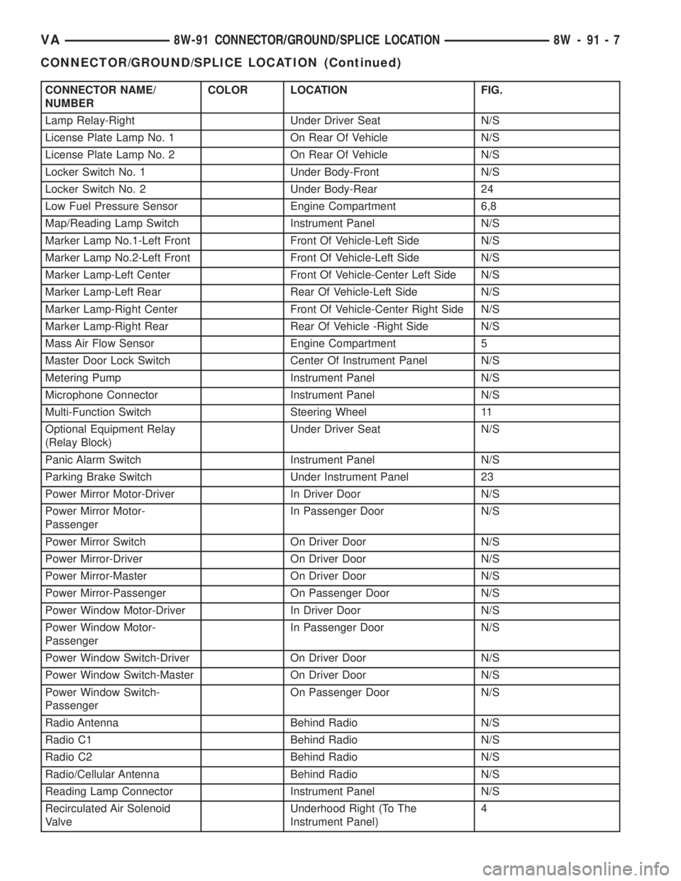
CONNECTOR NAME/
NUMBERCOLOR LOCATION FIG.
Lamp Relay-Right Under Driver Seat N/S
License Plate Lamp No. 1 On Rear Of Vehicle N/S
License Plate Lamp No. 2 On Rear Of Vehicle N/S
Locker Switch No. 1 Under Body-Front N/S
Locker Switch No. 2 Under Body-Rear 24
Low Fuel Pressure Sensor Engine Compartment 6,8
Map/Reading Lamp Switch Instrument Panel N/S
Marker Lamp No.1-Left Front Front Of Vehicle-Left Side N/S
Marker Lamp No.2-Left Front Front Of Vehicle-Left Side N/S
Marker Lamp-Left Center Front Of Vehicle-Center Left Side N/S
Marker Lamp-Left Rear Rear Of Vehicle-Left Side N/S
Marker Lamp-Right Center Front Of Vehicle-Center Right Side N/S
Marker Lamp-Right Rear Rear Of Vehicle -Right Side N/S
Mass Air Flow Sensor Engine Compartment 5
Master Door Lock Switch Center Of Instrument Panel N/S
Metering Pump Instrument Panel N/S
Microphone Connector Instrument Panel N/S
Multi-Function Switch Steering Wheel 11
Optional Equipment Relay
(Relay Block)Under Driver Seat N/S
Panic Alarm Switch Instrument Panel N/S
Parking Brake Switch Under Instrument Panel 23
Power Mirror Motor-Driver In Driver Door N/S
Power Mirror Motor-
PassengerIn Passenger Door N/S
Power Mirror Switch On Driver Door N/S
Power Mirror-Driver On Driver Door N/S
Power Mirror-Master On Driver Door N/S
Power Mirror-Passenger On Passenger Door N/S
Power Window Motor-Driver In Driver Door N/S
Power Window Motor-
PassengerIn Passenger Door N/S
Power Window Switch-Driver On Driver Door N/S
Power Window Switch-Master On Driver Door N/S
Power Window Switch-
PassengerOn Passenger Door N/S
Radio Antenna Behind Radio N/S
Radio C1 Behind Radio N/S
Radio C2 Behind Radio N/S
Radio/Cellular Antenna Behind Radio N/S
Reading Lamp Connector Instrument Panel N/S
Recirculated Air Solenoid
ValveUnderhood Right (To The
Instrument Panel)4
VA8W-91 CONNECTOR/GROUND/SPLICE LOCATION 8W - 91 - 7
CONNECTOR/GROUND/SPLICE LOCATION (Continued)
Page 704 of 1232
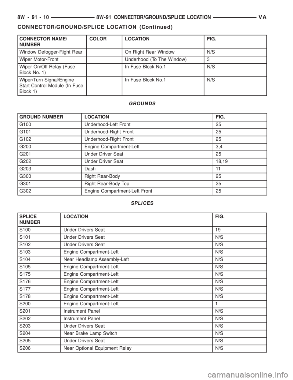
CONNECTOR NAME/
NUMBERCOLOR LOCATION FIG.
Window Defogger-Right Rear On Right Rear Window N/S
Wiper Motor-Front Underhood (To The Window) 3
Wiper On/Off Relay (Fuse
Block No. 1)In Fuse Block No.1 N/S
Wiper/Turn Signal/Engine
Start Control Module (In Fuse
Block 1)In Fuse Block No.1 N/S
GROUNDS
GROUND NUMBER LOCATION FIG.
G100 Underhood-Left Front 25
G101 Underhood-Right Front 25
G102 Underhood-Right Front 25
G200 Engine Compartment-Left 3,4
G201 Under Driver Seat 25
G202 Under Driver Seat 18,19
G203 Dash 11
G300 Right Rear-Body 25
G301 Right Rear-Body Top 25
G302 Engine Compartment-Left Front 25
SPLICES
SPLICE
NUMBERLOCATION FIG.
S100 Under Drivers Seat 19
S101 Under Drivers Seat N/S
S102 Under Drivers Seat N/S
S103 Engine Compartment-Left N/S
S104 Near Headlamp Assembly-Left N/S
S105 Engine Compartment-Left N/S
S175 Engine Compartment-Left N/S
S176 Engine Compartment-Left N/S
S177 Engine Compartment-Left N/S
S178 Engine Compartment-Left N/S
S200 Engine Compartment-Left 1
S201 Instrument Panel N/S
S202 Instrument Panel N/S
S203 Under Drivers Seat N/S
S204 Near Brake Lamp Switch N/S
S205 Under Drivers Seat N/S
S206 Near Optional Equipment Relay N/S
8W - 91 - 10 8W-91 CONNECTOR/GROUND/SPLICE LOCATIONVA
CONNECTOR/GROUND/SPLICE LOCATION (Continued)
Page 706 of 1232
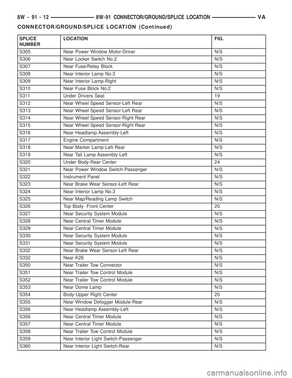
SPLICE
NUMBERLOCATION FIG.
S305 Near Power Window Motor-Driver N/S
S306 Near Locker Switch No.2 N/S
S307 Near Fuse/Relay Block N/S
S308 Near Interior Lamp No.3 N/S
S309 Near Interior Lamp-Right N/S
S310 Near Fuse Block No.2 N/S
S311 Under Drivers Seat 19
S312 Near Wheel Speed Sensor-Left Rear N/S
S313 Near Wheel Speed Sensor-Left Rear N/S
S314 Near Wheel Speed Sensor-Right Rear N/S
S315 Near Wheel Speed Sensor-Right Rear N/S
S316 Near Headlamp Assembly-Left N/S
S317 Engine Compartment N/S
S318 Near Marker Lamp-Left Rear N/S
S319 Near Tail Lamp Assembly-Left N/S
S320 Under Body-Rear Center 24
S321 Near Power Window Switch-Passenger N/S
S322 Instrument Panel N/S
S323 Near Brake Wear Sensor-Left Rear N/S
S324 Near Interior Lamp No.3 N/S
S325 Near Map/Reading Lamp Switch N/S
S326 Top Body- Front Center 20
S327 Near Security System Module N/S
S328 Near Central Timer Module N/S
S329 Near Central Timer Module N/S
S330 Near Security System Module N/S
S331 Near Security System Module N/S
S332 Near Brake Wear Sensor-Left Rear N/S
S332 Near K26 N/S
S350 Near Trailer Tow Connector N/S
S351 Near Trailer Tow Control Module N/S
S352 Near Trailer Tow Control Module N/S
S353 Near Dome Lamp N/S
S354 Body-Upper Right Center 20
S355 Near Window Defogger Module-Rear N/S
S356 Near Headlamp Assembly-Left N/S
S356 Near Central Timer Module N/S
S357 Near Central Timer Module N/S
S358 Near Trailer Tow Control Module N/S
S359 Near Interior Light Switch-Passenger N/S
S360 Near Interior Light Switch-Rear N/S
8W - 91 - 12 8W-91 CONNECTOR/GROUND/SPLICE LOCATIONVA
CONNECTOR/GROUND/SPLICE LOCATION (Continued)
Page 743 of 1232
(2) Remove the hood.
(3) Drain cooling system (Refer to 7 - COOLING/
ENGINE/COOLANT - STANDARD PROCEDURE).
(4) Evacuate and recover air conditioning system
(Refer to 24 - HEATING & AIR CONDITIONING/
PLUMBING - STANDARD PROCEDURE).
(5) Disconnect the engine wiring harness at the
vehicle side and carefully guide though the cowl into
the engine area.
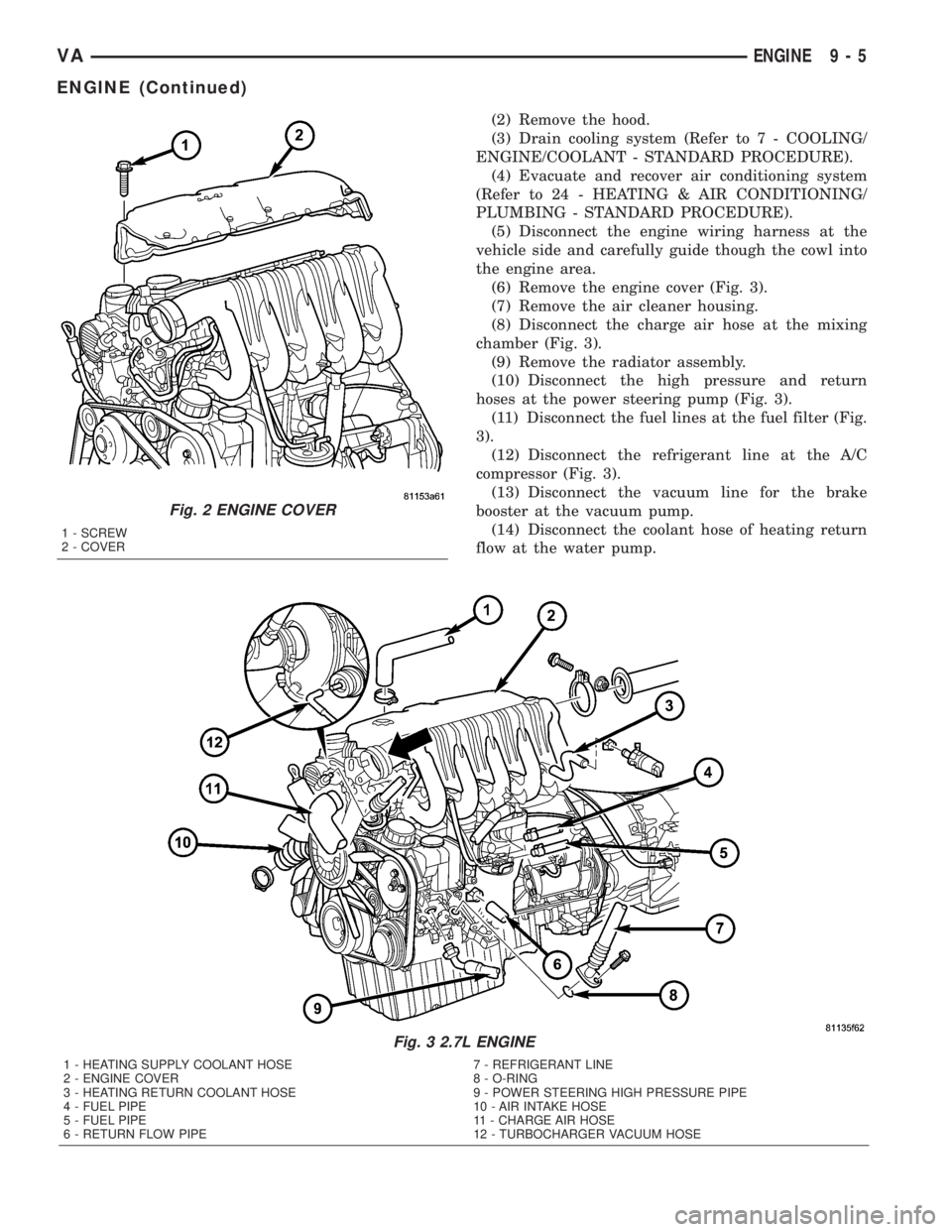
(6) Remove the engine cover (Fig. 3).
(7) Remove the air cleaner housing.
(8) Disconnect the charge air hose at the mixing
chamber (Fig. 3).
(9) Remove the radiator assembly.
(10) Disconnect the high pressure and return
hoses at the power steering pump (Fig. 3).
(11) Disconnect the fuel lines at the fuel filter (Fig.
3).
(12) Disconnect the refrigerant line at the A/C
compressor (Fig. 3).
(13) Disconnect the vacuum line for the brake
booster at the vacuum pump.
(14) Disconnect the coolant hose of heating return
flow at the water pump.
Fig. 3 2.7L ENGINE
1 - HEATING SUPPLY COOLANT HOSE 7 - REFRIGERANT LINE
2 - ENGINE COVER 8 - O-RING
3 - HEATING RETURN COOLANT HOSE 9 - POWER STEERING HIGH PRESSURE PIPE
4 - FUEL PIPE 10 - AIR INTAKE HOSE
5 - FUEL PIPE 11 - CHARGE AIR HOSE
6 - RETURN FLOW PIPE 12 - TURBOCHARGER VACUUM HOSE
Fig. 2 ENGINE COVER
1 - SCREW
2 - COVER
VAENGINE 9 - 5
ENGINE (Continued)
Page 746 of 1232
(11) Install the transmission cooler lines to trans-
mission.(Refer to 21 - TRANSMISSION/TRANS-
AXLE/AUTOMATIC - NAG1 - INSTALLATION) for
correct sequence and torque specification.
(12) Install transmission electrical connector and
shifter hardware.Refer to (Refer to 21 - TRANSMIS-
SION/TRANSAXLE/AUTOMATIC - NAG1 - INSTAL-
LATION) for correct sequence and torque
specification.
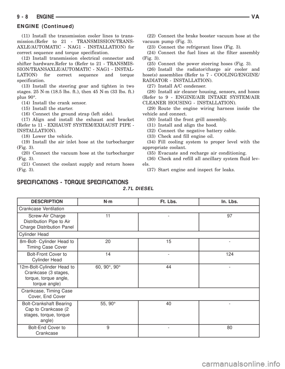
(13) Install the steering gear and tighten in two
stages. 25 N´m (18.5 lbs. ft.), then 45 N´m (33 lbs. ft.)
plus 90É.
(14) Install the crank sensor.
(15) Install the starter.
(16) Connect the ground strap (left side).
(17) Align and install the exhaust and bracket
(Refer to 11 - EXHAUST SYSTEM/EXHAUST PIPE -
INSTALLATION).
(18) Lower the vehicle.
(19) Install the air inlet hose at the turbocharger
(Fig. 3).
(20) Connect the vacuum hose at the turbocharger
(Fig. 3).
(21) Connect the coolant supply and return hoses
(Fig. 3).(22) Connect the brake booster vacuum hose at the
vacuum pump (Fig. 3).
(23) Connect the refrigerant lines (Fig. 3).
(24) Connect the fuel lines at the filter assembly
(Fig. 3).
(25) Connect the power steering hoses (Fig. 3).
(26) Install the radiator/charge air cooler and
hose(s) assemblies (Refer to 7 - COOLING/ENGINE/
RADIATOR - INSTALLATION).
(27) Install A/C condenser.
(28) Install air cleaner housing, sensors, and hoses
(Refer to 9 - ENGINE/AIR INTAKE SYSTEM/AIR
CLEANER HOUSING - INSTALLATION).
(29) Route the engine wiring harness inside the
vehicle and connect.
(30) Install the front grill assembly.
(31) Install and align the hood.
(32) Connect the negative battery cable.
(33) Check and fill engine oil.
(34) Fill cooling system to proper level with the
appropriate coolant.
(35) Evacuate and recharge air conditioning.
(36) Check and refill all ancillary system fluid lev-
els.
(37) Start engine and inspect for leaks.
SPECIFICATIONS - TORQUE SPECIFICATIONS
2.7L DIESEL
DESCRIPTION N´m Ft. Lbs. In. Lbs.
Crankcase Ventilation
Screw-Air Charge
Distribution Pipe to Air
Charge Distribution Panel11 - 9 7
Cylinder Head
8m-Bolt- Cylinder Head to
Timing Case Cover20 15 -
Bolt-Front Cover to
Cylinder Head14 - 124
12m-Bolt-Cylinder Head to
Crankcase (3 stages,
torque, torque angle,
torque angle)60, 90É, 90É 44 -
Crankcase, Timing Case
Cover, End Cover
Bolt-Crankshaft Bearing
Cap to Crankcase (2
stages, torque, torque
angle)55, 90É 40 -
Bolt-End Cover to
Crankcase9-80
9 - 8 ENGINEVA
ENGINE (Continued)
Page 816 of 1232
TURBOCHARGER
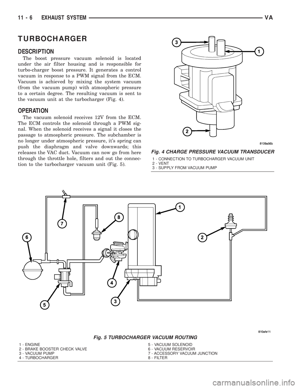
DESCRIPTION
The boost pressure vacuum solenoid is located
under the air filter housing and is responsible for
turbo-charger boost pressure. It generates a control
vacuum in response to a PWM signal from the ECM.
Vacuum is achieved by mixing the system vacuum
(from the vacuum pump) with atmospheric pressure
to a certain degree. The resulting vacuum is sent to
the vacuum unit at the turbocharger (Fig. 4).
OPERATION
The vacuum solenoid receives 12V from the ECM.
The ECM controls the solenoid through a PWM sig-
nal. When the solenoid receives a signal it closes the
passage to atmospheric pressure. The subchamber is
no longer under atmospheric pressure, it's spring can
push the diaphragm and valve downwards; this
releases the VAC duct. Vacuum can now go from here
through the throttle hole, filters and out the connec-
tion to the turbocharger vacuum unit (Fig. 5).
Fig. 4 CHARGE PRESSURE VACUUM TRANSDUCER
1 - CONNECTION TO TURBOCHARGER VACUUM UNIT
2 - VENT
3 - SUPPLY FROM VACUUM PUMP
Fig. 5 TURBOCHARGER VACUUM ROUTING
1 - ENGINE 5 - VACUUM SOLENOID
2 - BRAKE BOOSTER CHECK VALVE 6 - VACUUM RESERVOIR
3 - VACUUM PUMP 7 - ACCESSORY VACUUM JUNCTION
4 - TURBOCHARGER 8 - FILTER
11 - 6 EXHAUST SYSTEMVA
Page 824 of 1232
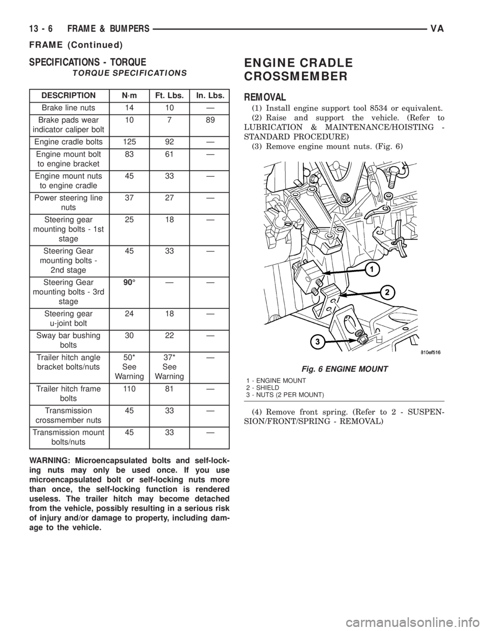
SPECIFICATIONS - TORQUE
TORQUE SPECIFICATIONS
DESCRIPTION N´m Ft. Lbs. In. Lbs.
Brake line nuts 14 10 Ð
Brake pads wear
indicator caliper bolt10 7 89
Engine cradle bolts 125 92 Ð
Engine mount bolt
to engine bracket83 61 Ð
Engine mount nuts
to engine cradle45 33 Ð
Power steering line
nuts37 27 Ð
Steering gear
mounting bolts - 1st
stage25 18 Ð
Steering Gear
mounting bolts -
2nd stage45 33 Ð
Steering Gear
mounting bolts - 3rd
stage90ÉÐÐ
Steering gear
u-joint bolt24 18 Ð
Sway bar bushing
bolts30 22 Ð
Trailer hitch angle
bracket bolts/nuts50*
See
Warning37*
See
WarningÐ
Trailer hitch frame
bolts11 0 8 1 Ð
Transmission
crossmember nuts45 33 Ð
Transmission mount
bolts/nuts45 33 Ð
WARNING: Microencapsulated bolts and self-lock-
ing nuts may only be used once. If you use
microencapsulated bolt or self-locking nuts more
than once, the self-locking function is rendered
useless. The trailer hitch may become detached
from the vehicle, possibly resulting in a serious risk
of injury and/or damage to property, including dam-
age to the vehicle.
ENGINE CRADLE
CROSSMEMBER
REMOVAL
(1) Install engine support tool 8534 or equivalent.
(2) Raise and support the vehicle. (Refer to
LUBRICATION & MAINTENANCE/HOISTING -
STANDARD PROCEDURE)
(3) Remove engine mount nuts. (Fig. 6)
(4) Remove front spring. (Refer to 2 - SUSPEN-
SION/FRONT/SPRING - REMOVAL)
Fig. 6 ENGINE MOUNT
1 - ENGINE MOUNT
2 - SHIELD
3 - NUTS (2 PER MOUNT)
13 - 6 FRAME & BUMPERSVA
FRAME (Continued)
Page 825 of 1232
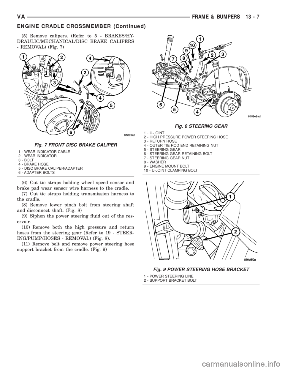
(5) Remove calipers. (Refer to 5 - BRAKES/HY-
DRAULIC/MECHANICAL/DISC BRAKE CALIPERS
- REMOVAL) (Fig. 7)
(6) Cut tie straps holding wheel speed sensor and
brake pad wear sensor wire harness to the cradle.
(7) Cut tie straps holding transmission harness to
the cradle.
(8) Remove lower pinch bolt from steering shaft
and disconnect shaft. (Fig. 8)
(9) Siphon the power steering fluid out of the res-
ervoir.
(10) Remove both the high pressure and return
hoses from the steering gear (Refer to 19 - STEER-
ING/PUMP/HOSES - REMOVAL) (Fig. 8).
(11) Remove bolt and remove power steering hose
support bracket from the cradle. (Fig. 9)
Fig. 7 FRONT DISC BRAKE CALIPER
1 - WEAR INDICATOR CABLE
2 - WEAR INDICATOR
3 - BOLT
4 - BRAKE HOSE
5 - DISC BRAKE CALIPER/ADAPTER
6 - ADAPTER BOLTS
Fig. 8 STEERING GEAR
1 - U-JOINT
2 - HIGH PRESSURE POWER STEERING HOSE
3 - RETURN HOSE
4 - OUTER TIE ROD END RETAINING NUT
5 - STEERING GEAR
6 - STEERING GEAR RETAINING BOLT
7 - STEERING GEAR NUT
8 - WASHER
9 - ENGINE MOUNT BOLT
10 - U-JOINT CLAMPING BOLT
Fig. 9 POWER STEERING HOSE BRACKET
1 - POWER STEERING LINE
2 - SUPPORT BRACKET BOLT
VAFRAME & BUMPERS 13 - 7
ENGINE CRADLE CROSSMEMBER (Continued)