2005 MERCEDES-BENZ SPRINTER brake
[x] Cancel search: brakePage 909 of 1232
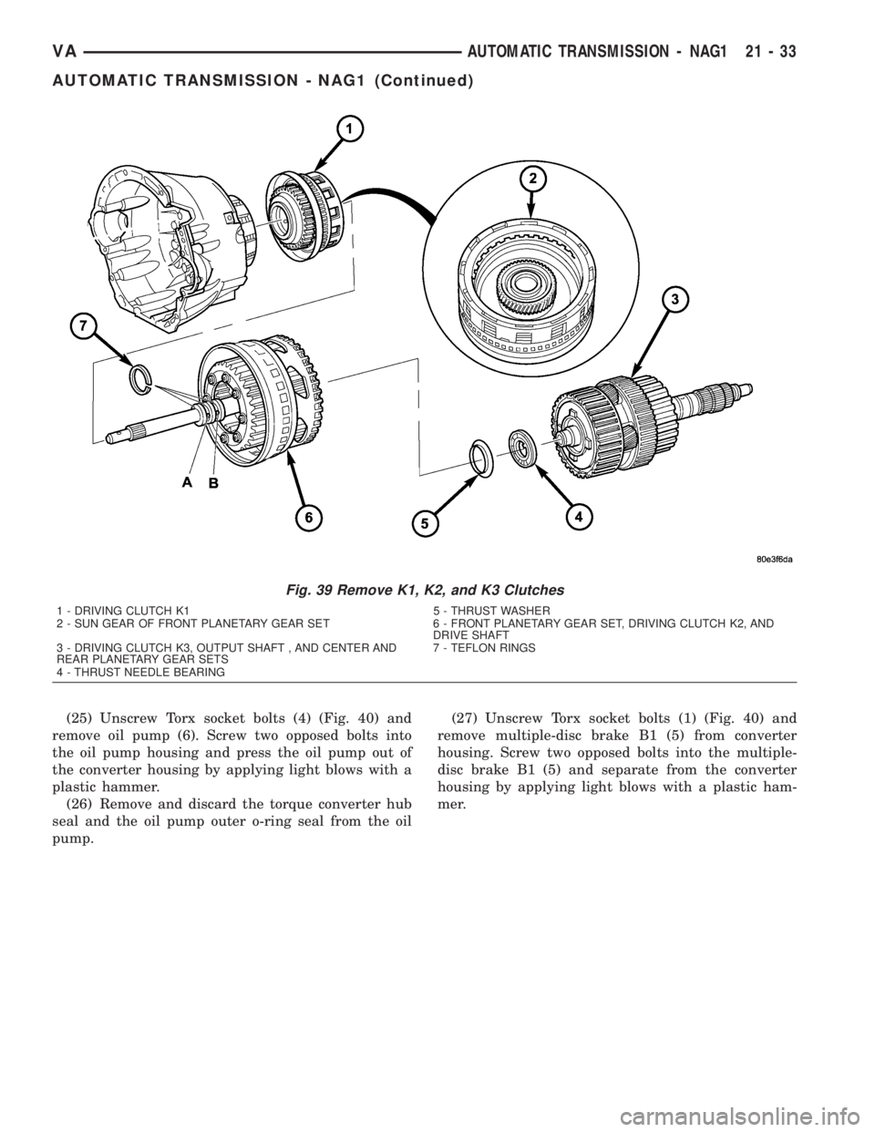
(25) Unscrew Torx socket bolts (4) (Fig. 40) and
remove oil pump (6). Screw two opposed bolts into
the oil pump housing and press the oil pump out of
the converter housing by applying light blows with a
plastic hammer.
(26) Remove and discard the torque converter hub
seal and the oil pump outer o-ring seal from the oil
pump.(27) Unscrew Torx socket bolts (1) (Fig. 40) and
remove multiple-disc brake B1 (5) from converter
housing. Screw two opposed bolts into the multiple-
disc brake B1 (5) and separate from the converter
housing by applying light blows with a plastic ham-
mer.
Fig. 39 Remove K1, K2, and K3 Clutches
1 - DRIVING CLUTCH K1 5 - THRUST WASHER
2 - SUN GEAR OF FRONT PLANETARY GEAR SET 6 - FRONT PLANETARY GEAR SET, DRIVING CLUTCH K2, AND
DRIVE SHAFT
3 - DRIVING CLUTCH K3, OUTPUT SHAFT , AND CENTER AND
REAR PLANETARY GEAR SETS7 - TEFLON RINGS
4 - THRUST NEEDLE BEARING
VAAUTOMATIC TRANSMISSION - NAG1 21 - 33
AUTOMATIC TRANSMISSION - NAG1 (Continued)
Page 910 of 1232
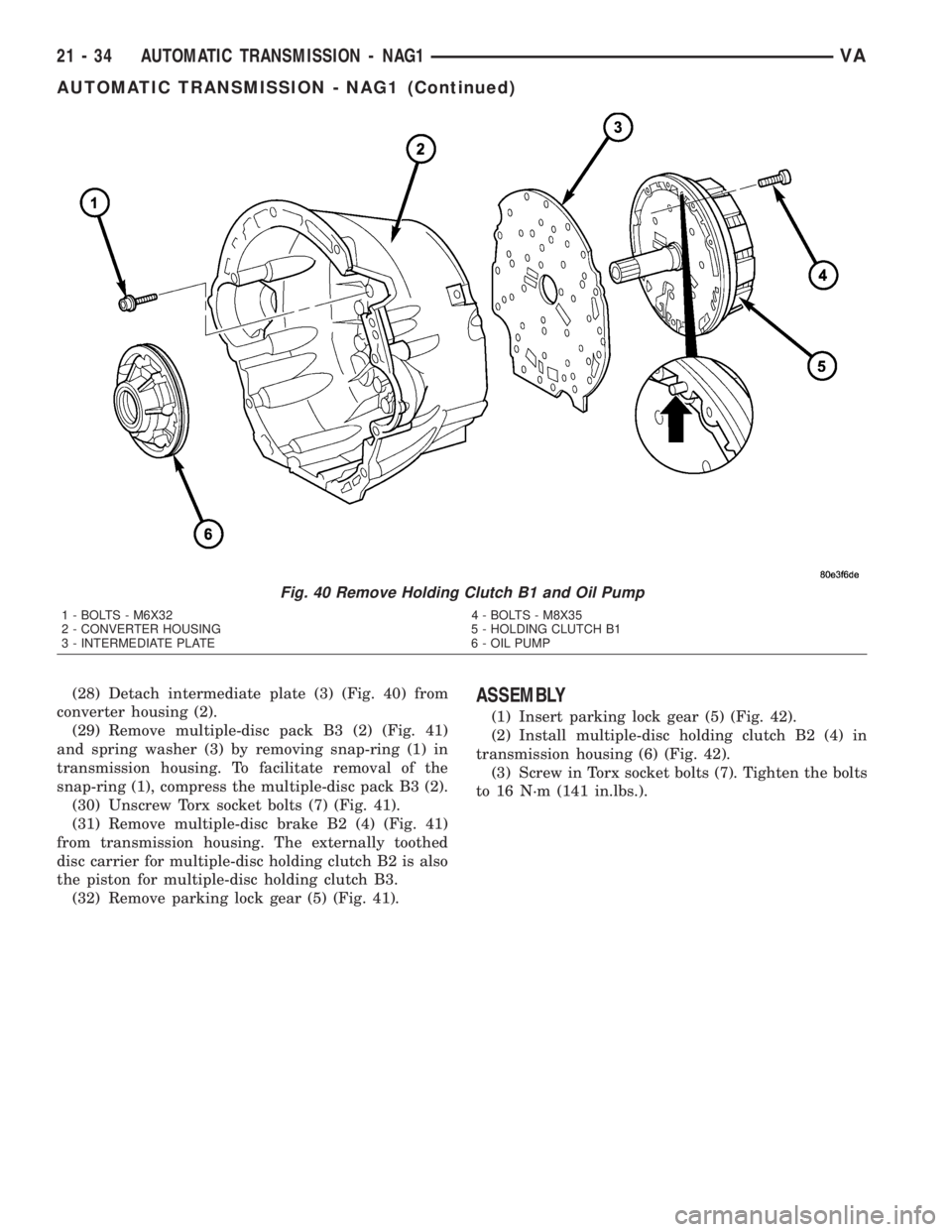
(28) Detach intermediate plate (3) (Fig. 40) from
converter housing (2).
(29) Remove multiple-disc pack B3 (2) (Fig. 41)
and spring washer (3) by removing snap-ring (1) in
transmission housing. To facilitate removal of the
snap-ring (1), compress the multiple-disc pack B3 (2).
(30) Unscrew Torx socket bolts (7) (Fig. 41).
(31) Remove multiple-disc brake B2 (4) (Fig. 41)
from transmission housing. The externally toothed
disc carrier for multiple-disc holding clutch B2 is also
the piston for multiple-disc holding clutch B3.
(32) Remove parking lock gear (5) (Fig. 41).ASSEMBLY
(1) Insert parking lock gear (5) (Fig. 42).
(2) Install multiple-disc holding clutch B2 (4) in
transmission housing (6) (Fig. 42).
(3) Screw in Torx socket bolts (7). Tighten the bolts
to 16 N´m (141 in.lbs.).
Fig. 40 Remove Holding Clutch B1 and Oil Pump
1 - BOLTS - M6X32 4 - BOLTS - M8X35
2 - CONVERTER HOUSING 5 - HOLDING CLUTCH B1
3 - INTERMEDIATE PLATE 6 - OIL PUMP
21 - 34 AUTOMATIC TRANSMISSION - NAG1VA
AUTOMATIC TRANSMISSION - NAG1 (Continued)
Page 912 of 1232
NOTE: During the measurement the snap ring (7)
(Fig. 43) must contact the upper bearing surface of
the groove in the outer multiple-disc carrier (8).
NOTE: Pay attention to sequence of discs. Place
new friction multiple-discs in ATF fluid for one hour
before installing.
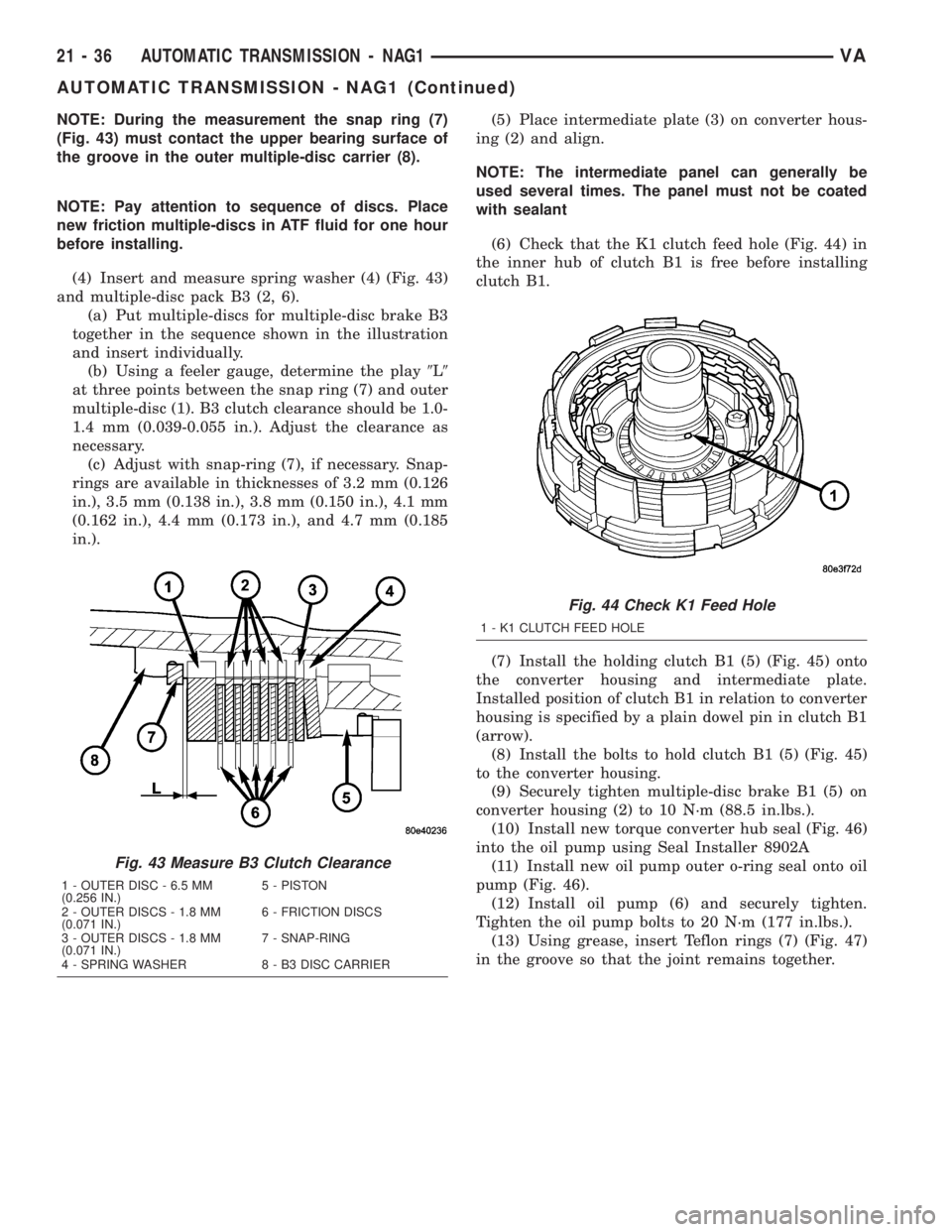
(4) Insert and measure spring washer (4) (Fig. 43)
and multiple-disc pack B3 (2, 6).
(a) Put multiple-discs for multiple-disc brake B3
together in the sequence shown in the illustration
and insert individually.
(b) Using a feeler gauge, determine the play9L9
at three points between the snap ring (7) and outer
multiple-disc (1). B3 clutch clearance should be 1.0-
1.4 mm (0.039-0.055 in.). Adjust the clearance as
necessary.
(c) Adjust with snap-ring (7), if necessary. Snap-
rings are available in thicknesses of 3.2 mm (0.126
in.), 3.5 mm (0.138 in.), 3.8 mm (0.150 in.), 4.1 mm
(0.162 in.), 4.4 mm (0.173 in.), and 4.7 mm (0.185
in.).(5) Place intermediate plate (3) on converter hous-
ing (2) and align.
NOTE: The intermediate panel can generally be
used several times. The panel must not be coated
with sealant
(6) Check that the K1 clutch feed hole (Fig. 44) in
the inner hub of clutch B1 is free before installing
clutch B1.
(7) Install the holding clutch B1 (5) (Fig. 45) onto
the converter housing and intermediate plate.
Installed position of clutch B1 in relation to converter
housing is specified by a plain dowel pin in clutch B1
(arrow).
(8) Install the bolts to hold clutch B1 (5) (Fig. 45)
to the converter housing.
(9) Securely tighten multiple-disc brake B1 (5) on
converter housing (2) to 10 N´m (88.5 in.lbs.).
(10) Install new torque converter hub seal (Fig. 46)
into the oil pump using Seal Installer 8902A
(11) Install new oil pump outer o-ring seal onto oil
pump (Fig. 46).
(12) Install oil pump (6) and securely tighten.
Tighten the oil pump bolts to 20 N´m (177 in.lbs.).
(13) Using grease, insert Teflon rings (7) (Fig. 47)
in the groove so that the joint remains together.
Fig. 43 Measure B3 Clutch Clearance
1 - OUTER DISC - 6.5 MM
(0.256 IN.)5 - PISTON
2 - OUTER DISCS - 1.8 MM
(0.071 IN.)6 - FRICTION DISCS
3 - OUTER DISCS - 1.8 MM
(0.071 IN.)7 - SNAP-RING
4 - SPRING WASHER 8 - B3 DISC CARRIER
Fig. 44 Check K1 Feed Hole
1 - K1 CLUTCH FEED HOLE
21 - 36 AUTOMATIC TRANSMISSION - NAG1VA
AUTOMATIC TRANSMISSION - NAG1 (Continued)
Page 965 of 1232
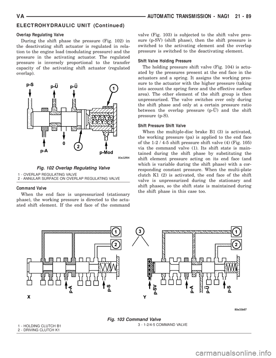
Overlap Regulating Valve
During the shift phase the pressure (Fig. 102) in
the deactivating shift actuator is regulated in rela-
tion to the engine load (modulating pressure) and the
pressure in the activating actuator. The regulated
pressure is inversely proportional to the transfer
capacity of the activating shift actuator (regulated
overlap).
Command Valve
When the end face is unpressurized (stationary
phase), the working pressure is directed to the actu-
ated shift element. If the end face of the commandvalve (Fig. 103) is subjected to the shift valve pres-
sure (p-SV) (shift phase), then the shift pressure is
switched to the activating element and the overlap
pressure is switched to the deactivating element.
Shift Valve Holding Pressure
The holding pressure shift valve (Fig. 104) is actu-
ated by the pressures present at the end face in the
actuators and a spring. It assigns the working pres-
sure to the actuator with the higher pressure (taking
into account the spring force and the effective surface
area). The other element of the shift group is then
unpressurized. The valve switches over only during
the shift phase and only at a certain pressure ratio
between the overlap pressure (p-š) and the shift
pressure (p-S).
Shift Pressure Shift Valve
When the multiple-disc brake B1 (3) is activated,
the working pressure (pa) is applied to the end face
of the 1-2 / 4-5 shift pressure shift valve (4) (Fig. 105)
via the command valve (1). Its shift state is main-
tained during the shift phase by substituting the
shift element pressure acting on its end face (and
which is variable during the shift phase) with a cor-
responding constant pressure. When the multi-plate
clutch K1 (2) is activated, the end face of the shift
valve is unpressurized during the stationary and
shift phases, so the shift state is maintained during
the shift phase in this case too.
Fig. 103 Command Valve
1 - HOLDING CLUTCH B1
2 - DRIVING CLUTCH K13 - 1-2/4-5 COMMAND VALVE
Fig. 102 Overlap Regulating Valve
1 - OVERLAP REGULATING VALVE
2 - ANNULAR SURFACE ON OVERLAP REGULATING VALVE
VAAUTOMATIC TRANSMISSION - NAG1 21 - 89
ELECTROHYDRAULIC UNIT (Continued)
Page 979 of 1232
(4) Actuate the service brake. Start engine and let
it run at idle speed in selector lever position9P9.
(5) Shift through the transmission modes several
times with the vehicle stationary and the engine
idling
(6) Warm up the transmission, wait at least 2 min-
utes and check the oil level with the engine running.
Push the Oil Dipstick 8863A in up to the stop on the
electrohydraulic unit and pull out again, read off oil
level, repeat if necessary.
NOTE: The dipstick will protrude from the fill tube
approximately 75mm (3 inches) when installed.
(7) Check transmission oil temperature.
NOTE: The true transmission oil temperature can
only be read by a scan tool in REVERSE or any for-
ward gear position. (Refer to 21 - AUTOMATIC
TRANSMISSION- NAG1/TRANSMISSION TEMPERA-
TURE SENSOR/PARK-NEUTRAL SWITCH - OPERA-
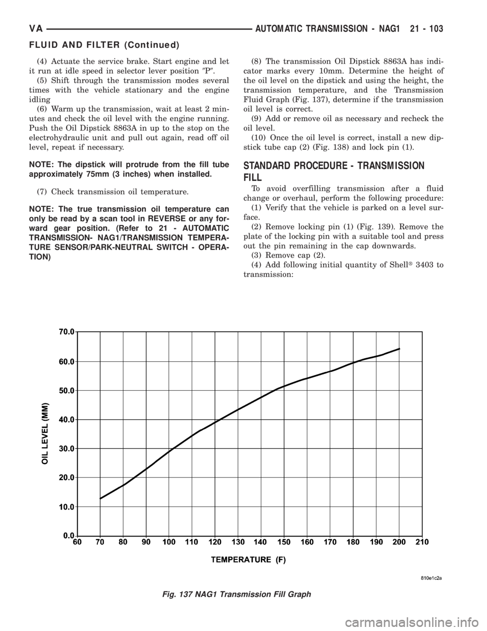
TION)(8) The transmission Oil Dipstick 8863A has indi-
cator marks every 10mm. Determine the height of
the oil level on the dipstick and using the height, the
transmission temperature, and the Transmission
Fluid Graph (Fig. 137), determine if the transmission
oil level is correct.
(9) Add or remove oil as necessary and recheck the
oil level.
(10) Once the oil level is correct, install a new dip-
stick tube cap (2) (Fig. 138) and lock pin (1).
STANDARD PROCEDURE - TRANSMISSION
FILL
To avoid overfilling transmission after a fluid
change or overhaul, perform the following procedure:
(1) Verify that the vehicle is parked on a level sur-
face.
(2) Remove locking pin (1) (Fig. 139). Remove the
plate of the locking pin with a suitable tool and press
out the pin remaining in the cap downwards.
(3) Remove cap (2).
(4) Add following initial quantity of Shellt3403 to
transmission:
Fig. 137 NAG1 Transmission Fill Graph
VAAUTOMATIC TRANSMISSION - NAG1 21 - 103
FLUID AND FILTER (Continued)
Page 985 of 1232
GEARSHIFT CABLE
DIAGNOSIS AND TESTING - GEARSHIFT
CABLE
(1) The floor shifter lever and gate positions
should be in alignment with all transmission PARK,
NEUTRAL, and gear detent positions.
(2) Engine starts must be possible with floor shift
lever in PARK or NEUTRAL gate positions only.
Engine starts must not be possible in any other gear
position.
(3) With floor shift lever handle push-button not
depressed and lever in:
(a) PARK position - Apply forward force on cen-
ter of handle and remove pressure. Engine starts
must be possible.
(b) PARK position - Apply rearward force on cen-
ter of handle and remove pressure. Engine starts
must be possible.
(c) NEUTRAL position - Normal position. Engine
starts must be possible.
(d) NEUTRAL position - Engine running and
brakes applied, apply forward force on center of
shift handle. Transmission shall not be able to shift
from NEUTRAL to REVERSE.
REMOVAL
(1) Move selector lever to position9D9.
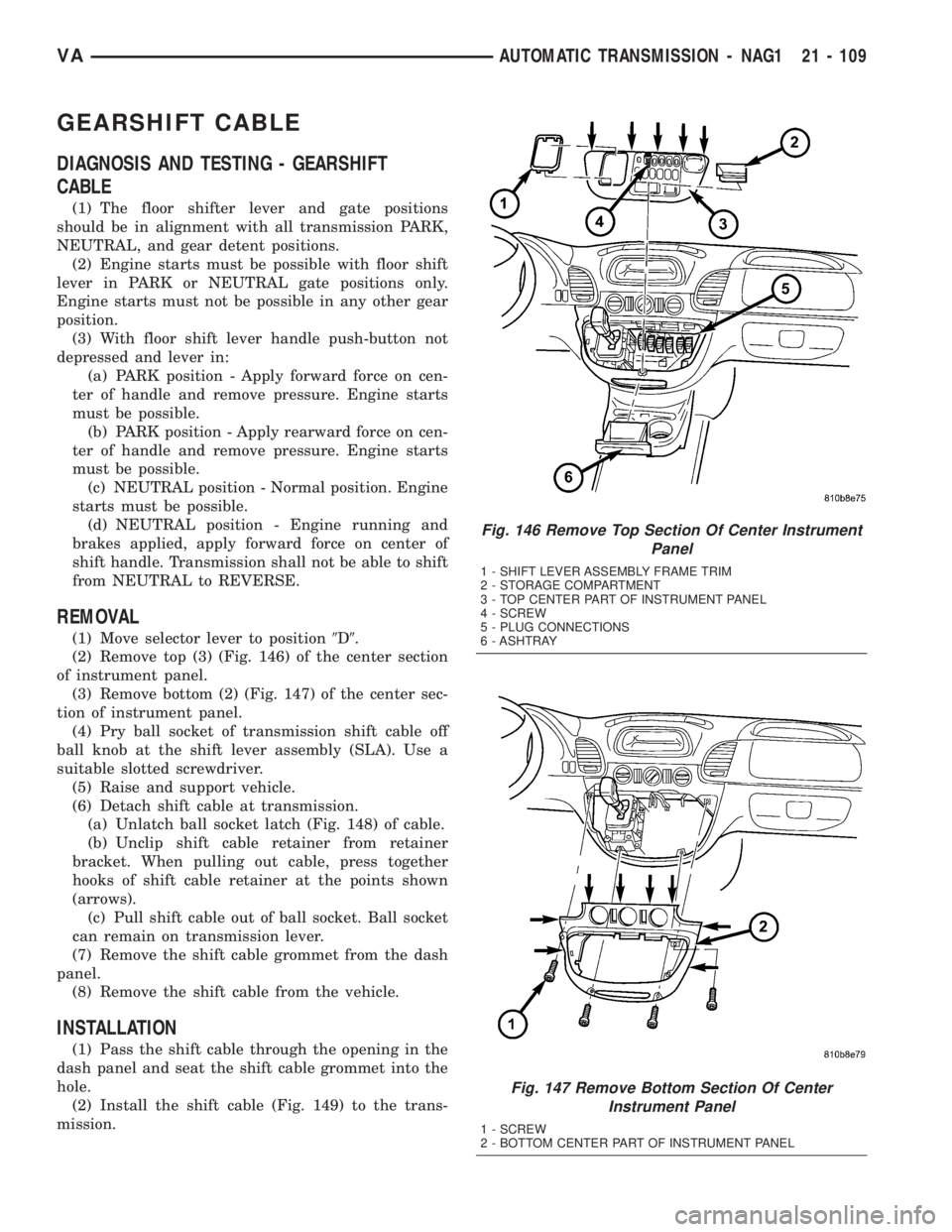
(2) Remove top (3) (Fig. 146) of the center section
of instrument panel.
(3) Remove bottom (2) (Fig. 147) of the center sec-
tion of instrument panel.
(4) Pry ball socket of transmission shift cable off
ball knob at the shift lever assembly (SLA). Use a
suitable slotted screwdriver.
(5) Raise and support vehicle.
(6) Detach shift cable at transmission.
(a) Unlatch ball socket latch (Fig. 148) of cable.
(b) Unclip shift cable retainer from retainer
bracket. When pulling out cable, press together
hooks of shift cable retainer at the points shown
(arrows).
(c) Pull shift cable out of ball socket. Ball socket
can remain on transmission lever.
(7) Remove the shift cable grommet from the dash
panel.
(8) Remove the shift cable from the vehicle.
INSTALLATION
(1) Pass the shift cable through the opening in the
dash panel and seat the shift cable grommet into the
hole.
(2) Install the shift cable (Fig. 149) to the trans-
mission.
Fig. 146 Remove Top Section Of Center Instrument
Panel
1 - SHIFT LEVER ASSEMBLY FRAME TRIM
2 - STORAGE COMPARTMENT
3 - TOP CENTER PART OF INSTRUMENT PANEL
4 - SCREW
5 - PLUG CONNECTIONS
6 - ASHTRAY
Fig. 147 Remove Bottom Section Of Center
Instrument Panel
1 - SCREW
2 - BOTTOM CENTER PART OF INSTRUMENT PANEL
VAAUTOMATIC TRANSMISSION - NAG1 21 - 109
Page 988 of 1232
OPERATION
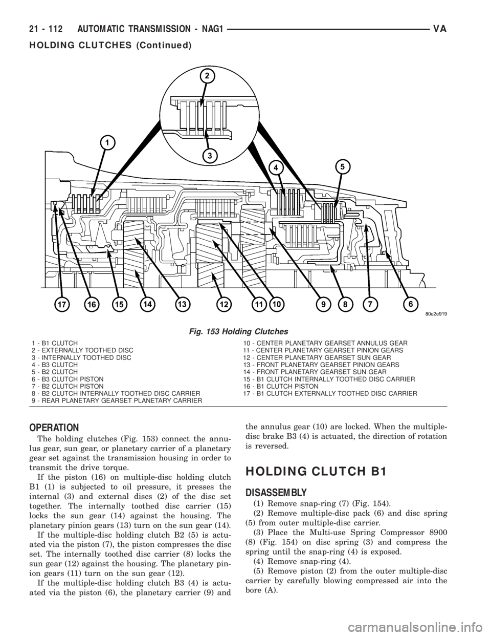
The holding clutches (Fig. 153) connect the annu-
lus gear, sun gear, or planetary carrier of a planetary
gear set against the transmission housing in order to
transmit the drive torque.
If the piston (16) on multiple-disc holding clutch
B1 (1) is subjected to oil pressure, it presses the
internal (3) and external discs (2) of the disc set
together. The internally toothed disc carrier (15)
locks the sun gear (14) against the housing. The
planetary pinion gears (13) turn on the sun gear (14).
If the multiple-disc holding clutch B2 (5) is actu-
ated via the piston (7), the piston compresses the disc
set. The internally toothed disc carrier (8) locks the
sun gear (12) against the housing. The planetary pin-
ion gears (11) turn on the sun gear (12).
If the multiple-disc holding clutch B3 (4) is actu-
ated via the piston (6), the planetary carrier (9) andthe annulus gear (10) are locked. When the multiple-
disc brake B3 (4) is actuated, the direction of rotation
is reversed.
HOLDING CLUTCH B1
DISASSEMBLY
(1) Remove snap-ring (7) (Fig. 154).
(2) Remove multiple-disc pack (6) and disc spring
(5) from outer multiple-disc carrier.
(3) Place the Multi-use Spring Compressor 8900
(8) (Fig. 154) on disc spring (3) and compress the
spring until the snap-ring (4) is exposed.
(4) Remove snap-ring (4).
(5) Remove piston (2) from the outer multiple-disc
carrier by carefully blowing compressed air into the
bore (A).
Fig. 153 Holding Clutches
1 - B1 CLUTCH 10 - CENTER PLANETARY GEARSET ANNULUS GEAR
2 - EXTERNALLY TOOTHED DISC 11 - CENTER PLANETARY GEARSET PINION GEARS
3 - INTERNALLY TOOTHED DISC 12 - CENTER PLANETARY GEARSET SUN GEAR
4 - B3 CLUTCH 13 - FRONT PLANETARY GEARSET PINION GEARS
5 - B2 CLUTCH 14 - FRONT PLANETARY GEARSET SUN GEAR
6 - B3 CLUTCH PISTON 15 - B1 CLUTCH INTERNALLY TOOTHED DISC CARRIER
7 - B2 CLUTCH PISTON 16 - B1 CLUTCH PISTON
8 - B2 CLUTCH INTERNALLY TOOTHED DISC CARRIER 17 - B1 CLUTCH EXTERNALLY TOOTHED DISC CARRIER
9 - REAR PLANETARY GEARSET PLANETARY CARRIER
21 - 112 AUTOMATIC TRANSMISSION - NAG1VA
HOLDING CLUTCHES (Continued)
Page 1006 of 1232
PLANETARY GEARTRAIN
DESCRIPTION
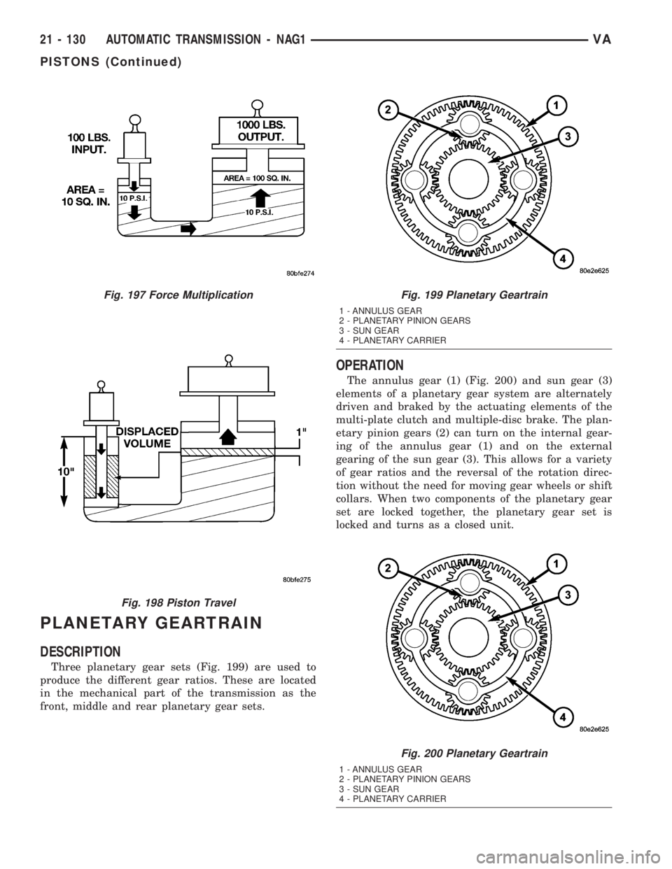
Three planetary gear sets (Fig. 199) are used to
produce the different gear ratios. These are located
in the mechanical part of the transmission as the
front, middle and rear planetary gear sets.
OPERATION
The annulus gear (1) (Fig. 200) and sun gear (3)
elements of a planetary gear system are alternately
driven and braked by the actuating elements of the
multi-plate clutch and multiple-disc brake. The plan-
etary pinion gears (2) can turn on the internal gear-
ing of the annulus gear (1) and on the external
gearing of the sun gear (3). This allows for a variety
of gear ratios and the reversal of the rotation direc-
tion without the need for moving gear wheels or shift
collars. When two components of the planetary gear
set are locked together, the planetary gear set is
locked and turns as a closed unit.
Fig. 197 Force Multiplication
Fig. 198 Piston Travel
Fig. 199 Planetary Geartrain
1 - ANNULUS GEAR
2 - PLANETARY PINION GEARS
3 - SUN GEAR
4 - PLANETARY CARRIER
Fig. 200 Planetary Geartrain
1 - ANNULUS GEAR
2 - PLANETARY PINION GEARS
3 - SUN GEAR
4 - PLANETARY CARRIER
21 - 130 AUTOMATIC TRANSMISSION - NAG1VA
PISTONS (Continued)