2005 MERCEDES-BENZ SPRINTER brake
[x] Cancel search: brakePage 826 of 1232
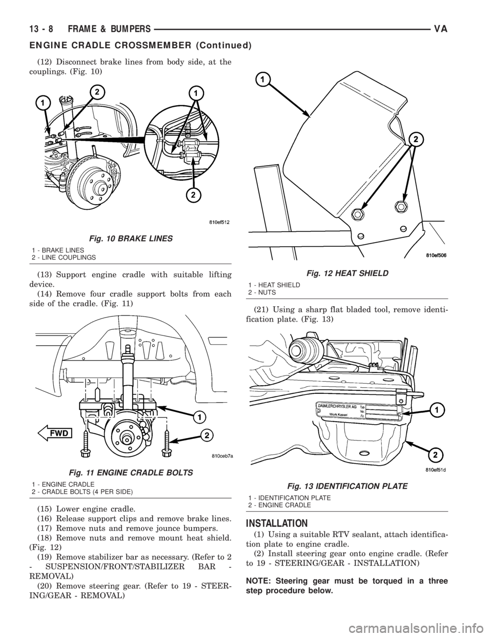
(12) Disconnect brake lines from body side, at the
couplings. (Fig. 10)
(13) Support engine cradle with suitable lifting
device.
(14) Remove four cradle support bolts from each
side of the cradle. (Fig. 11)
(15) Lower engine cradle.
(16) Release support clips and remove brake lines.
(17) Remove nuts and remove jounce bumpers.
(18) Remove nuts and remove mount heat shield.
(Fig. 12)
(19) Remove stabilizer bar as necessary. (Refer to 2
- SUSPENSION/FRONT/STABILIZER BAR -
REMOVAL)
(20) Remove steering gear. (Refer to 19 - STEER-
ING/GEAR - REMOVAL)(21) Using a sharp flat bladed tool, remove identi-
fication plate. (Fig. 13)
INSTALLATION
(1) Using a suitable RTV sealant, attach identifica-
tion plate to engine cradle.
(2) Install steering gear onto engine cradle. (Refer
to 19 - STEERING/GEAR - INSTALLATION)
NOTE: Steering gear must be torqued in a three
step procedure below.
Fig. 10 BRAKE LINES
1 - BRAKE LINES
2 - LINE COUPLINGS
Fig. 11 ENGINE CRADLE BOLTS
1 - ENGINE CRADLE
2 - CRADLE BOLTS (4 PER SIDE)
Fig. 12 HEAT SHIELD
1 - HEAT SHIELD
2 - NUTS
Fig. 13 IDENTIFICATION PLATE
1 - IDENTIFICATION PLATE
2 - ENGINE CRADLE
13 - 8 FRAME & BUMPERSVA
ENGINE CRADLE CROSSMEMBER (Continued)
Page 827 of 1232
(3) Tighten steering gear bolts in three stages as
follows.
1. Tighten to 25 N´m (18 ft. lbs.)
2. Then tighten to 45 N´m (33 ft. lbs.)
3. Then tighten bolts an additional 90É.
(4) Install stabilizer bar. (Refer to 2 - SUSPEN-
SION/FRONT/STABILIZER BAR - INSTALLATION)
(5) Install heat shield and nuts.
(6) Install jounce bumpers and install nuts.
(7) Install support clips and brake lines.
(8) Raise engine cradle into place and install bolts.
(9) Tighten bolts to 125 N´m (92 ft. lbs.).
(10) Connect brake lines at couplings and tighten
to 14 N´m (10 ft. lbs.).
(11) Position power steering hose and install sup-
port bracket bolt.
(12) Install both power steering hoses at steering
gear. (Refer to 19 - STEERING/PUMP/HOSES -
INSTALLATION)
(13) Connect steering shaft to gear and install the
lower pinch bolt.
(14) Tighten lower pinch bolt to 24 N´m (18 ft.
lbs.).
(15) Install new tie straps holding transmission
harness to cradle.
(16) Install front spring. (Refer to 2 - SUSPEN-
SION/FRONT/SPRING - INSTALLATION)
(17) Install engine mount nuts and tighten to 45
N´m (33 ft. lbs.).
(18) Install calipers. (Refer to 5 - BRAKES/HY-
DRAULIC/MECHANICAL/DISC BRAKE CALIPERS
- INSTALLATION)
(19) Install new tie straps holding wheel speed
sensors and brake pad wear sensors wire harness to
cradle.
(20) Check and align vehicle to specifications.
(Refer to 2 - SUSPENSION/WHEEL ALIGNMENT -
STANDARD PROCEDURE)
REAR CROSSMEMBER -
TRANSMISSION
REMOVAL
(1) Raise and support the vehicle. (Refer to
LUBRICATION & MAINTENANCE/HOISTING -
STANDARD PROCEDURE)
(2) Support transmission with a suitable lifting
device.
(3) Remove the bolts/nuts and remove transmis-
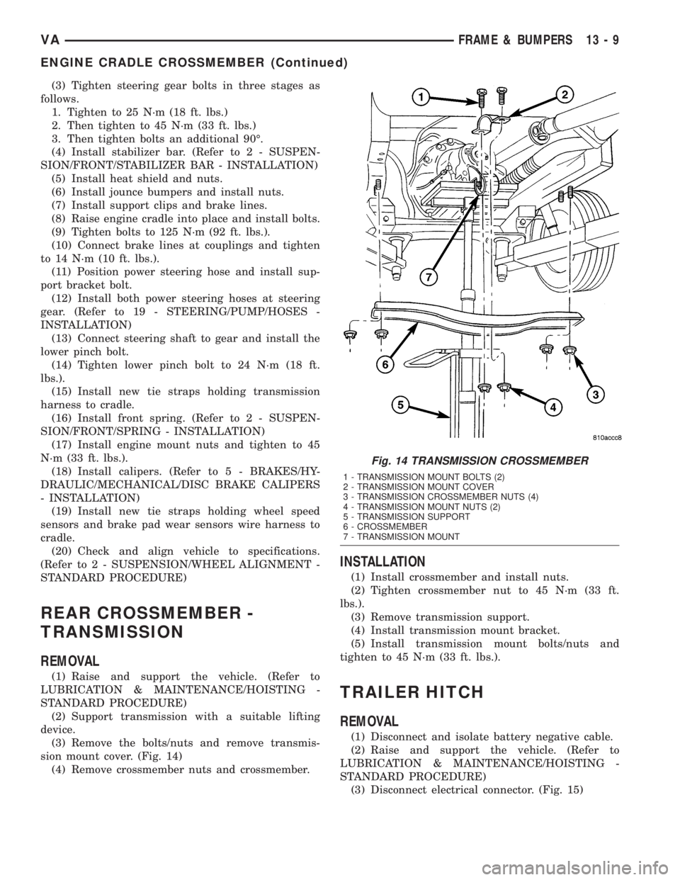
sion mount cover. (Fig. 14)
(4) Remove crossmember nuts and crossmember.
INSTALLATION
(1) Install crossmember and install nuts.
(2) Tighten crossmember nut to 45 N´m (33 ft.
lbs.).
(3) Remove transmission support.
(4) Install transmission mount bracket.
(5) Install transmission mount bolts/nuts and
tighten to 45 N´m (33 ft. lbs.).
TRAILER HITCH
REMOVAL
(1) Disconnect and isolate battery negative cable.
(2) Raise and support the vehicle. (Refer to
LUBRICATION & MAINTENANCE/HOISTING -
STANDARD PROCEDURE)
(3) Disconnect electrical connector. (Fig. 15)
Fig. 14 TRANSMISSION CROSSMEMBER
1 - TRANSMISSION MOUNT BOLTS (2)
2 - TRANSMISSION MOUNT COVER
3 - TRANSMISSION CROSSMEMBER NUTS (4)
4 - TRANSMISSION MOUNT NUTS (2)
5 - TRANSMISSION SUPPORT
6 - CROSSMEMBER
7 - TRANSMISSION MOUNT
VAFRAME & BUMPERS 13 - 9
ENGINE CRADLE CROSSMEMBER (Continued)
Page 864 of 1232
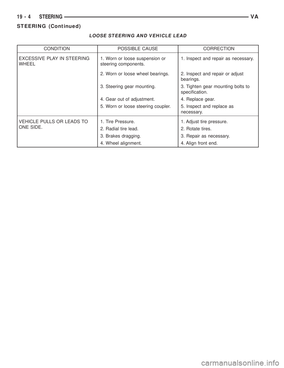
LOOSE STEERING AND VEHICLE LEAD
CONDITION POSSIBLE CAUSE CORRECTION
EXCESSIVE PLAY IN STEERING
WHEEL1. Worn or loose suspension or
steering components.1. Inspect and repair as necessary.
2. Worn or loose wheel bearings. 2. Inspect and repair or adjust
bearings.
3. Steering gear mounting. 3. Tighten gear mounting bolts to
specification.
4. Gear out of adjustment. 4. Replace gear.
5. Worn or loose steering coupler. 5. Inspect and replace as
necessary.
VEHICLE PULLS OR LEADS TO
ONE SIDE.1. Tire Pressure. 1. Adjust tire pressure.
2. Radial tire lead. 2. Rotate tires.
3. Brakes dragging. 3. Repair as necessary.
4. Wheel alignment. 4. Align front end.
19 - 4 STEERINGVA
STEERING (Continued)
Page 865 of 1232
COLUMN
TABLE OF CONTENTS
page page
COLUMN
SPECIFICATIONS - TORQUE CHART.........5
INTERMEDIATE SHAFT
REMOVAL.............................5
INSTALLATION..........................5
KEY/LOCK CYLINDER
REMOVAL.............................6INSTALLATION..........................7
STEERING WHEEL
REMOVAL.............................7
INSTALLATION..........................7
COLUMN
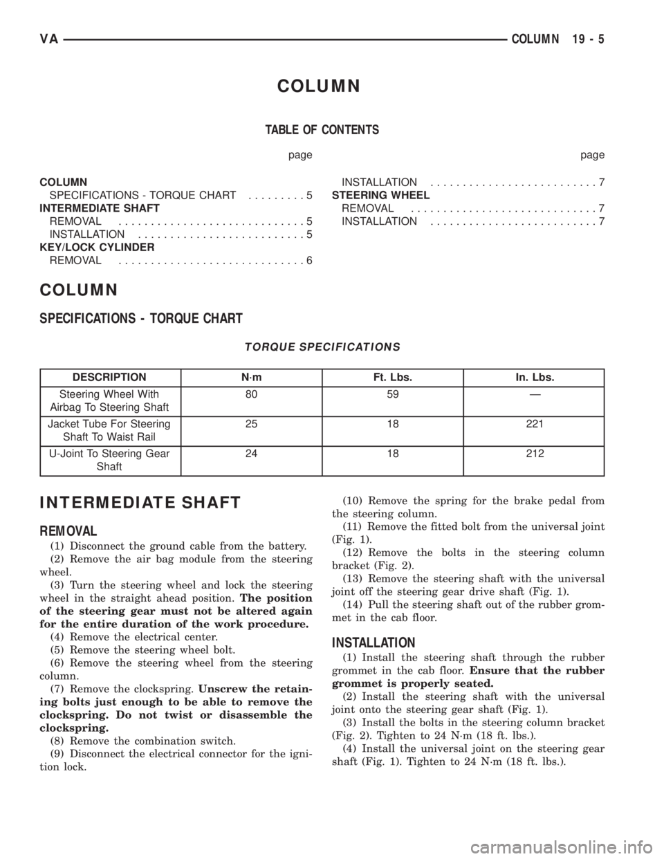
SPECIFICATIONS - TORQUE CHART
TORQUE SPECIFICATIONS
DESCRIPTION N´m Ft. Lbs. In. Lbs.
Steering Wheel With
Airbag To Steering Shaft80 59 Ð
Jacket Tube For Steering
Shaft To Waist Rail25 18 221
U-Joint To Steering Gear
Shaft24 18 212
INTERMEDIATE SHAFT
REMOVAL
(1) Disconnect the ground cable from the battery.
(2) Remove the air bag module from the steering
wheel.
(3) Turn the steering wheel and lock the steering
wheel in the straight ahead position.The position
of the steering gear must not be altered again
for the entire duration of the work procedure.
(4) Remove the electrical center.
(5) Remove the steering wheel bolt.
(6) Remove the steering wheel from the steering
column.
(7) Remove the clockspring.Unscrew the retain-
ing bolts just enough to be able to remove the
clockspring. Do not twist or disassemble the
clockspring.
(8) Remove the combination switch.
(9) Disconnect the electrical connector for the igni-
tion lock.(10) Remove the spring for the brake pedal from
the steering column.
(11) Remove the fitted bolt from the universal joint
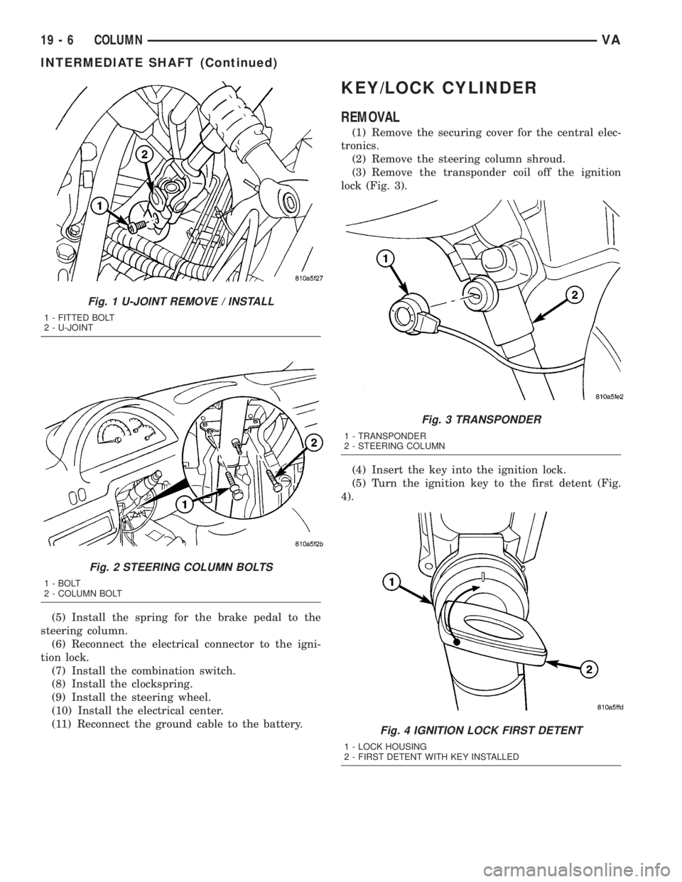
(Fig. 1).
(12) Remove the bolts in the steering column
bracket (Fig. 2).
(13) Remove the steering shaft with the universal
joint off the steering gear drive shaft (Fig. 1).
(14) Pull the steering shaft out of the rubber grom-
met in the cab floor.
INSTALLATION
(1) Install the steering shaft through the rubber
grommet in the cab floor.Ensure that the rubber
grommet is properly seated.
(2) Install the steering shaft with the universal
joint onto the steering gear shaft (Fig. 1).
(3) Install the bolts in the steering column bracket
(Fig. 2). Tighten to 24 N´m (18 ft. lbs.).
(4) Install the universal joint on the steering gear
shaft (Fig. 1). Tighten to 24 N´m (18 ft. lbs.).
VACOLUMN 19 - 5
Page 866 of 1232
(5) Install the spring for the brake pedal to the
steering column.
(6) Reconnect the electrical connector to the igni-
tion lock.
(7) Install the combination switch.
(8) Install the clockspring.
(9) Install the steering wheel.
(10) Install the electrical center.
(11) Reconnect the ground cable to the battery.
KEY/LOCK CYLINDER
REMOVAL
(1) Remove the securing cover for the central elec-
tronics.
(2) Remove the steering column shroud.
(3) Remove the transponder coil off the ignition
lock (Fig. 3).
(4) Insert the key into the ignition lock.
(5) Turn the ignition key to the first detent (Fig.
4).
Fig. 1 U-JOINT REMOVE / INSTALL
1 - FITTED BOLT
2 - U-JOINT
Fig. 2 STEERING COLUMN BOLTS
1 - BOLT
2 - COLUMN BOLT
Fig. 3 TRANSPONDER
1 - TRANSPONDER
2 - STEERING COLUMN
Fig. 4 IGNITION LOCK FIRST DETENT
1 - LOCK HOUSING
2 - FIRST DETENT WITH KEY INSTALLED
19 - 6 COLUMNVA
INTERMEDIATE SHAFT (Continued)
Page 900 of 1232
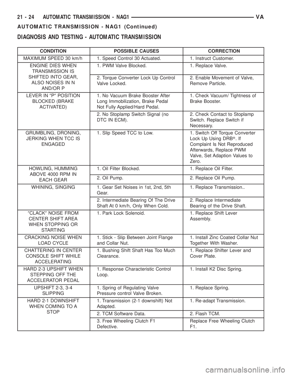
DIAGNOSIS AND TESTING - AUTOMATIC TRANSMISSION
CONDITION POSSIBLE CAUSES CORRECTION
MAXIMUM SPEED 30 km/h 1. Speed Control 30 Actuated. 1. Instruct Customer.
ENGINE DIES WHEN
TRANSMISSION IS
SHIFTED INTO GEAR,
ALSO NOISES IN N
AND/OR P1. PWM Valve Blocked. 1. Replace Valve.
2. Torque Converter Lock Up Control
Valve Locked.2. Enable Movement of Valve,
Remove Particle.
LEVER IN9P9POSITION
BLOCKED (BRAKE
ACTIVATED)1. No Vacuum Brake Booster After
Long Immobilization, Brake Pedal
Not Fully Applied/Hard Pedal.1. Check Vacuum/ Tightness of
Brake Booster.
2. No Stoplamp Switch Signal (no
DTC IN ECM).2. Check Contact to Stoplamp
Switch. Replace Switch if
Necessary.
GRUMBLING, DRONING,
JERKING WHEN TCC IS
ENGAGED1. Slip Speed TCC to Low. 1. Switch Off Torque Converter
Lock Up Using DRBT.If
Complaint Is Not Reproduced
Afterwards, Replace PWM
Valve, Set Adaption Values to
Zero.
HOWLING, HUMMING
ABOVE 4000 RPM IN
EACH GEAR1. Oil Filter Blocked. 1. Replace Oil Filter.
2. Oil Pump. 2. Replace Oil Pump.
WHINING, SINGING 1. Gear Set Noises in 1st, 2nd, 5th
Gear.1. Replace Transmission..
2. Intermediate Bearing Of The Drive
Shaft At 0 km/h, Only When Cold.2. Replace Intermediate
Bearing of the Drive Shaft.
9CLACK9NOISE FROM
CENTER SHIFT AREA
WHEN STOPPING OR
STARTING1. Park Lock Solenoid. 1. Replace Shift Lever
Assembly.
CRACKING NOISE WHEN
LOAD CYCLE1. Stick - Slip Between Joint Flange
and Collar Nut.1. Install Zinc Coated Collar Nut
Together With Washer.
CHATTERING IN CENTER
CONSOLE SHIFT WHILE
ACCELERATING1. Bushing Shift Shaft Has Too Much
Clearance.1. Replace Shifter Lever and
Cover Plate.
HARD 2-3 UPSHIFT WHEN
STEPPING OFF THE
ACCELERATOR PEDAL1. Response Characteristic Control
Loop.1. Install K2 Disc Spring.
UPSHIFT 2-3, 3-4
SLIPPING1. Spring of Regulating Valve
Pressure control Valve Broken.1. Replace Spring.
HARD 2-1 DOWNSHIFT
WHEN COMING TO A
STOP1. Transmission (2-1 downshift) Not
Adapted.1. Re-adapt Transmission.
2. TCM Software Data. 2. Flash TCM.
3. Free Wheeling Clutch F1
Defective.Replace Free Wheeling Clutch
F1.
21 - 24 AUTOMATIC TRANSMISSION - NAG1VA
AUTOMATIC TRANSMISSION - NAG1 (Continued)
Page 901 of 1232
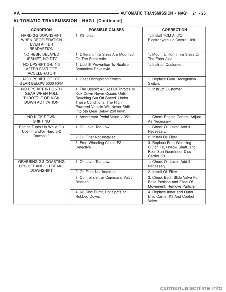
CONDITION POSSIBLE CAUSES CORRECTION
HARD 3-2 DOWNSHIFT
WHEN DECELERATION
EVEN AFTER
READAPTION1. K3 Idles. 1. Install TCM And/Or
Electrohydraulic Control Unit.
NO RESP. DELAYED
UPSHIFT, NO DTC1. Different Tire Sizes Are Mounted
On The Front Axle.1. Mount Uniform Tire Sizes On
The Front Axle.
NO UPSHIFT 3-4, 4-5
AFTER FAST OFF
(ACCELERATOR)1. Upshift Prevention To Realize
Dynamical Drivestyle.1. Instruct Customer.
NO UPSHIFT OF 1ST
GEAR BELOW 5000 RPM1. Gear Recognition Switch. 1. Replace Gear Recognition
Switch.
NO UPSHIFT INTO 5TH
GEAR WHEN FULL
THROTTLE OR KICK
DOWN ACTIVATION1. The Upshift 4-5 At Full Throttle or
Kick Down Never Occurs Until
Reaching Cut Off Speed. Under
These Conditions, The High
Powered Vehicle Will Never Shift
Into 5th Gear Below 250 km/h.1. Instruct Customer.
NO KICK DOWN
SHIFTING1. Accelerator Pedal Value < 95%. 1. Check Engine Control. Adjust
As Necessary.
Engine Turns Up While 2-3
Upshift and/or Hard 3-2
Downshift1. Oil Level Too Low. 1. Check Oil Level. Add if
Necessary.
2. Oil Filter Not Installed. 2. Install Oil Filter.
3. Free Wheeling Clutch F2
Defective.3. Replace Free Wheeling
Clutch F2, Hollow Shaft, and
Rear Sun Gear/Inner Disc
Carrier K3.
GRABBING 2-3 COASTING
UPSHIFT AND/OR BRAKE
DOWNSHIFT1. Oil Level Too Low. 1. Check Oil Level. Add if
Necessary.
2. Oil Filter Not Installed. 2. Install Oil Filter.
3. Control shift or Command Valve
Blocked.3. Check Each Slide Valve For
Base Position and Ease Of
Movement, Remove Particle.
4. K3 Disc Burnt, Hot Spots or
Rubbed Down.4. Replace Inner and Outer
Disc Carrier K3 And Control
Valve.
VAAUTOMATIC TRANSMISSION - NAG1 21 - 25
AUTOMATIC TRANSMISSION - NAG1 (Continued)
Page 903 of 1232
STANDARD PROCEDURE - ALUMINUM
THREAD REPAIR
Damaged or worn threads in the aluminum trans-
mission case and valve body can be repaired by the
use of Heli-CoilsŸ, or equivalent. This repair con-
sists of drilling out the worn-out damaged threads.
Then tap the hole with a special Heli-CoilŸ tap, or
equivalent, and installing a Heli-CoilŸ insert, or
equivalent, into the hole. This brings the hole back to
its original thread size.
Heli-CoilŸ, or equivalent, tools and inserts are
readily available from most automotive parts suppli-
ers.
REMOVAL
(1) Disconnect the negative (ground) battery cable.
CAUTION: Isolate ground lead to prevent accidental
contact.
(2) Apply parking brake.
(3) Move gear selector lever to position9N9.
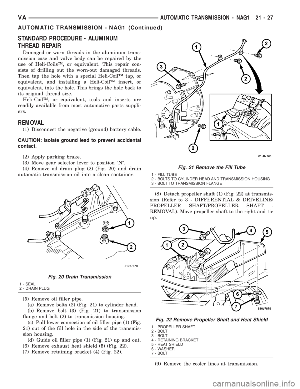
(4) Remove oil drain plug (2) (Fig. 20) and drain
automatic transmission oil into a clean container.
(5) Remove oil filler pipe.
(a) Remove bolts (2) (Fig. 21) to cylinder head.
(b) Remove bolt (3) (Fig. 21) to transmission
flange and bolt (2) to transmission housing.
(c) Pull lower connection of oil filler pipe (1) (Fig.
21) out of the fill hole in the side of the transmis-
sion housing.
(d) Guide oil filler pipe (1) (Fig. 21) up and out.
(6) Remove exhaust heat shield (5) (Fig. 22).
(7) Remove retaining bracket (4) (Fig. 22).(8) Detach propeller shaft (1) (Fig. 22) at transmis-
sion (Refer to 3 - DIFFERENTIAL & DRIVELINE/
PROPELLER SHAFT/PROPELLER SHAFT -
REMOVAL). Move propeller shaft to the right and tie
up.
(9) Remove the cooler lines at transmission.
Fig. 20 Drain Transmission
1 - SEAL
2 - DRAIN PLUG
Fig. 21 Remove the Fill Tube
1 - FILL TUBE
2 - BOLTS TO CYLINDER HEAD AND TRANSMISSION HOUSING
3 - BOLT TO TRANSMISSION FLANGE
Fig. 22 Remove Propeller Shaft and Heat Shield
1 - PROPELLER SHAFT
2 - BOLT
3 - BOLT
4 - RETAINING BRACKET
5 - HEAT SHIELD
6 - WASHER
7 - BOLT
VAAUTOMATIC TRANSMISSION - NAG1 21 - 27
AUTOMATIC TRANSMISSION - NAG1 (Continued)