2005 MERCEDES-BENZ SPRINTER brake
[x] Cancel search: brakePage 219 of 1232
REAR SIDE MARKER LAMP
BULB
REMOVAL
(1) Disconnect and isolate the battery negative
cable.
(2) If the vehicle is so equipped, remove the trim
from the inside of the right or left rear corner pillar.
(3) From inside the vehicle, use hand pressure to
push the two latch tabs toward the center of the tail
lamp unit socket plate and pull the socket plate
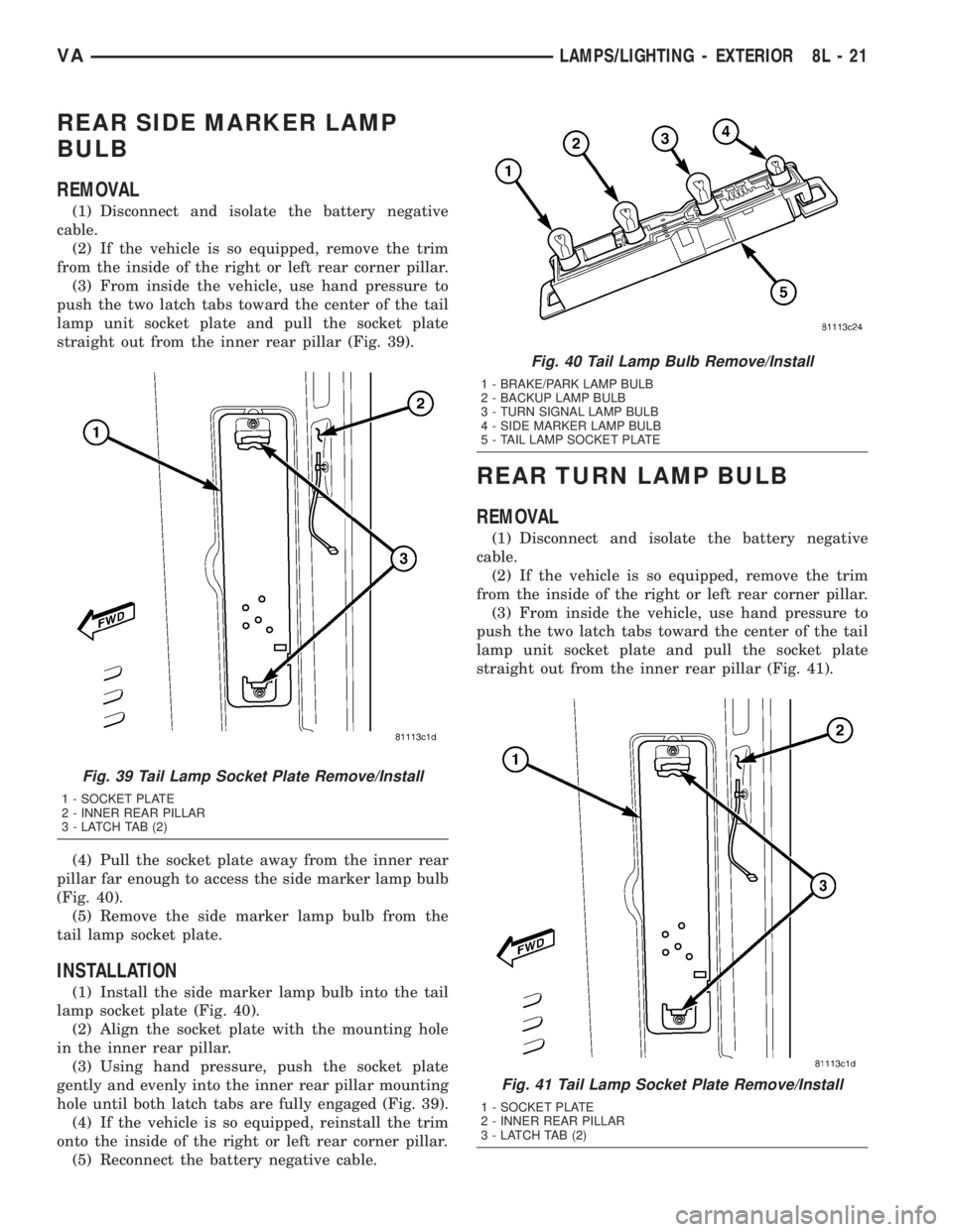
straight out from the inner rear pillar (Fig. 39).
(4) Pull the socket plate away from the inner rear
pillar far enough to access the side marker lamp bulb
(Fig. 40).
(5) Remove the side marker lamp bulb from the
tail lamp socket plate.
INSTALLATION
(1) Install the side marker lamp bulb into the tail
lamp socket plate (Fig. 40).
(2) Align the socket plate with the mounting hole
in the inner rear pillar.
(3) Using hand pressure, push the socket plate
gently and evenly into the inner rear pillar mounting
hole until both latch tabs are fully engaged (Fig. 39).
(4) If the vehicle is so equipped, reinstall the trim
onto the inside of the right or left rear corner pillar.
(5) Reconnect the battery negative cable.
REAR TURN LAMP BULB
REMOVAL
(1) Disconnect and isolate the battery negative
cable.
(2) If the vehicle is so equipped, remove the trim
from the inside of the right or left rear corner pillar.
(3) From inside the vehicle, use hand pressure to
push the two latch tabs toward the center of the tail
lamp unit socket plate and pull the socket plate
straight out from the inner rear pillar (Fig. 41).
Fig. 39 Tail Lamp Socket Plate Remove/Install
1 - SOCKET PLATE
2 - INNER REAR PILLAR
3 - LATCH TAB (2)
Fig. 40 Tail Lamp Bulb Remove/Install
1 - BRAKE/PARK LAMP BULB
2 - BACKUP LAMP BULB
3 - TURN SIGNAL LAMP BULB
4 - SIDE MARKER LAMP BULB
5 - TAIL LAMP SOCKET PLATE
Fig. 41 Tail Lamp Socket Plate Remove/Install
1 - SOCKET PLATE
2 - INNER REAR PILLAR
3 - LATCH TAB (2)
VALAMPS/LIGHTING - EXTERIOR 8L - 21
Page 220 of 1232
(4) Pull the socket plate away from the inner rear
pillar far enough to access the turn signal lamp bulb
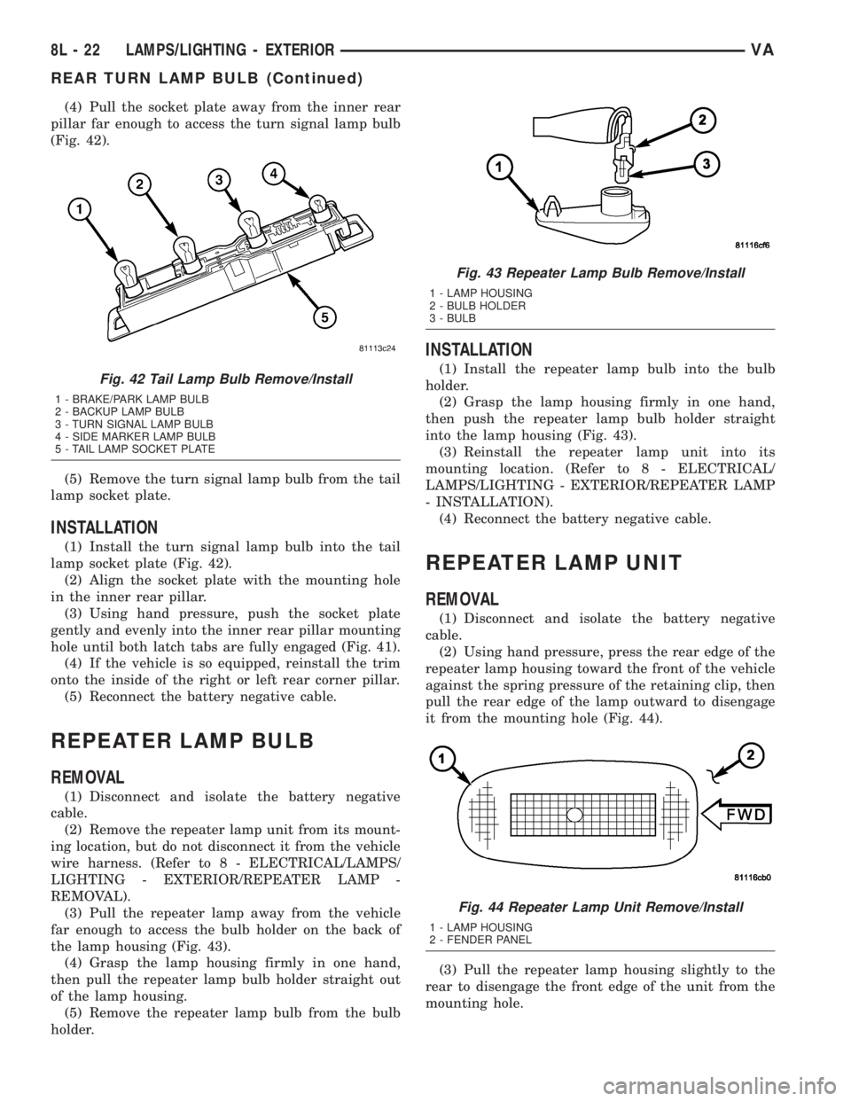
(Fig. 42).
(5) Remove the turn signal lamp bulb from the tail
lamp socket plate.
INSTALLATION
(1) Install the turn signal lamp bulb into the tail
lamp socket plate (Fig. 42).
(2) Align the socket plate with the mounting hole
in the inner rear pillar.
(3) Using hand pressure, push the socket plate
gently and evenly into the inner rear pillar mounting
hole until both latch tabs are fully engaged (Fig. 41).
(4) If the vehicle is so equipped, reinstall the trim
onto the inside of the right or left rear corner pillar.
(5) Reconnect the battery negative cable.
REPEATER LAMP BULB
REMOVAL
(1) Disconnect and isolate the battery negative
cable.
(2) Remove the repeater lamp unit from its mount-
ing location, but do not disconnect it from the vehicle
wire harness. (Refer to 8 - ELECTRICAL/LAMPS/
LIGHTING - EXTERIOR/REPEATER LAMP -
REMOVAL).
(3) Pull the repeater lamp away from the vehicle
far enough to access the bulb holder on the back of
the lamp housing (Fig. 43).
(4) Grasp the lamp housing firmly in one hand,
then pull the repeater lamp bulb holder straight out
of the lamp housing.
(5) Remove the repeater lamp bulb from the bulb
holder.
INSTALLATION
(1) Install the repeater lamp bulb into the bulb
holder.
(2) Grasp the lamp housing firmly in one hand,
then push the repeater lamp bulb holder straight
into the lamp housing (Fig. 43).
(3) Reinstall the repeater lamp unit into its
mounting location. (Refer to 8 - ELECTRICAL/
LAMPS/LIGHTING - EXTERIOR/REPEATER LAMP
- INSTALLATION).
(4) Reconnect the battery negative cable.
REPEATER LAMP UNIT
REMOVAL
(1) Disconnect and isolate the battery negative
cable.
(2) Using hand pressure, press the rear edge of the
repeater lamp housing toward the front of the vehicle
against the spring pressure of the retaining clip, then
pull the rear edge of the lamp outward to disengage
it from the mounting hole (Fig. 44).
(3) Pull the repeater lamp housing slightly to the
rear to disengage the front edge of the unit from the
mounting hole.
Fig. 42 Tail Lamp Bulb Remove/Install
1 - BRAKE/PARK LAMP BULB
2 - BACKUP LAMP BULB
3 - TURN SIGNAL LAMP BULB
4 - SIDE MARKER LAMP BULB
5 - TAIL LAMP SOCKET PLATE
Fig. 43 Repeater Lamp Bulb Remove/Install
1 - LAMP HOUSING
2 - BULB HOLDER
3 - BULB
Fig. 44 Repeater Lamp Unit Remove/Install
1 - LAMP HOUSING
2 - FENDER PANEL
8L - 22 LAMPS/LIGHTING - EXTERIORVA
REAR TURN LAMP BULB (Continued)
Page 273 of 1232
SPEED CONTROL
TABLE OF CONTENTS
page page
SPEED CONTROL
DESCRIPTION..........................1
OPERATION............................1
SPECIFICATIONS
TORQUE.............................2
CABLE
DESCRIPTION..........................3SERVO
DESCRIPTION..........................3
SWITCH
REMOVAL.............................3
INSTALLATION..........................3
SPEED CONTROL
DESCRIPTION
The speed control system is electronically con-
trolled by the Engine Control Module (ECM).A
cable and a vacuum controlled servo are not
used. This is a servo-less system.Control of the
system is accomplished by a 4-position, instrument
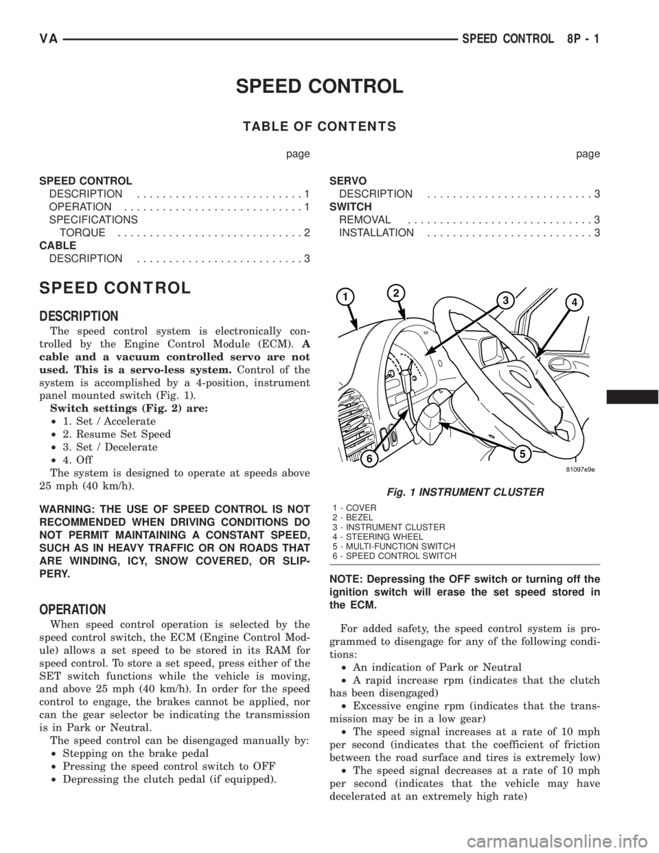
panel mounted switch (Fig. 1).
Switch settings (Fig. 2) are:
²1. Set / Accelerate
²2. Resume Set Speed
²3. Set / Decelerate
²4. Off
The system is designed to operate at speeds above
25 mph (40 km/h).
WARNING: THE USE OF SPEED CONTROL IS NOT
RECOMMENDED WHEN DRIVING CONDITIONS DO
NOT PERMIT MAINTAINING A CONSTANT SPEED,
SUCH AS IN HEAVY TRAFFIC OR ON ROADS THAT
ARE WINDING, ICY, SNOW COVERED, OR SLIP-
PERY.
OPERATION
When speed control operation is selected by the
speed control switch, the ECM (Engine Control Mod-
ule) allows a set speed to be stored in its RAM for
speed control. To store a set speed, press either of the
SET switch functions while the vehicle is moving,
and above 25 mph (40 km/h). In order for the speed
control to engage, the brakes cannot be applied, nor
can the gear selector be indicating the transmission
is in Park or Neutral.
The speed control can be disengaged manually by:
²Stepping on the brake pedal
²Pressing the speed control switch to OFF
²Depressing the clutch pedal (if equipped).NOTE: Depressing the OFF switch or turning off the
ignition switch will erase the set speed stored in
the ECM.
For added safety, the speed control system is pro-
grammed to disengage for any of the following condi-
tions:
²An indication of Park or Neutral
²A rapid increase rpm (indicates that the clutch
has been disengaged)
²Excessive engine rpm (indicates that the trans-
mission may be in a low gear)
²The speed signal increases at a rate of 10 mph
per second (indicates that the coefficient of friction
between the road surface and tires is extremely low)
²The speed signal decreases at a rate of 10 mph
per second (indicates that the vehicle may have
decelerated at an extremely high rate)
Fig. 1 INSTRUMENT CLUSTER
1 - COVER
2 - BEZEL
3 - INSTRUMENT CLUSTER
4 - STEERING WHEEL
5 - MULTI-FUNCTION SWITCH
6 - SPEED CONTROL SWITCH
VASPEED CONTROL 8P - 1
Page 305 of 1232
WIRING
TABLE OF CONTENTS
page page
WIRING DIAGRAM INFORMATION....... 8W-01-1
COMPONENT INDEX.................. 8W-02-1
POWER DISTRIBUTION............... 8W-10-1
FUSE BLOCK........................ 8W-11-1
GROUND DISTRIBUTION.............. 8W-15-1
BUS COMMUNICATIONS.............. 8W-18-1
CHARGING SYSTEM.................. 8W-20-1
STARTING SYSTEM.................. 8W-21-1
FUEL/IGNITION SYSTEM.............. 8W-30-1
TRANSMISSION CONTROL SYSTEM..... 8W-31-1
VEHICLE SPEED CONTROL............ 8W-33-1
ANTILOCK BRAKES................... 8W-35-1
VEHICLE THEFT SECURITY SYSTEM..... 8W-39-1
INSTRUMENT CLUSTER............... 8W-40-1
HORN/CIGAR LIGHTER................ 8W-41-1
AIR CONDITIONER/HEATER............ 8W-42-1
AIRBAG SYSTEM.................... 8W-43-1
INTERIOR LIGHTING.................. 8W-44-1CENTRAL TIMER MODULE............. 8W-45-1
AUDIO SYSTEM..................... 8W-47-1
REAR WINDOW DEFOGGER............ 8W-48-1
FRONT LIGHTING.................... 8W-50-1
REAR LIGHTING..................... 8W-51-1
TURN SIGNALS...................... 8W-52-1
WIPERS............................ 8W-53-1
TRAILER TOW....................... 8W-54-1
NAVIGATION/TELECOMMUNICATIONS.... 8W-55-1
POWER WINDOWS................... 8W-60-1
POWER DOOR LOCKS................ 8W-61-1
POWER MIRRORS................... 8W-62-1
POWER SEATS...................... 8W-63-1
SPLICE INFORMATION................ 8W-70-1
CONNECTOR PIN-OUTS............... 8W-80-1
CONNECTOR/GROUND/SPLICE
LOCATION........................ 8W-91-1
POWER DISTRIBUTION............... 8W-97-1 VAWIRING 8W - 1
Page 312 of 1232
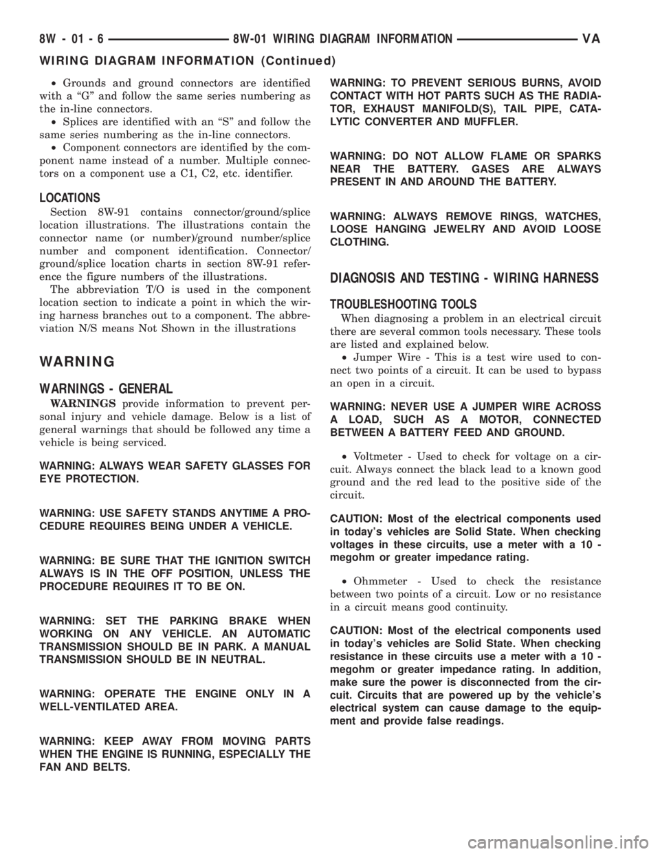
²Grounds and ground connectors are identified
with a ªGº and follow the same series numbering as
the in-line connectors.
²Splices are identified with an ªSº and follow the
same series numbering as the in-line connectors.
²Component connectors are identified by the com-
ponent name instead of a number. Multiple connec-
tors on a component use a C1, C2, etc. identifier.
LOCATIONS
Section 8W-91 contains connector/ground/splice
location illustrations. The illustrations contain the
connector name (or number)/ground number/splice
number and component identification. Connector/
ground/splice location charts in section 8W-91 refer-
ence the figure numbers of the illustrations.
The abbreviation T/O is used in the component
location section to indicate a point in which the wir-
ing harness branches out to a component. The abbre-
viation N/S means Not Shown in the illustrations
WARNING
WARNINGS - GENERAL
WARNINGSprovide information to prevent per-
sonal injury and vehicle damage. Below is a list of
general warnings that should be followed any time a
vehicle is being serviced.
WARNING: ALWAYS WEAR SAFETY GLASSES FOR
EYE PROTECTION.
WARNING: USE SAFETY STANDS ANYTIME A PRO-
CEDURE REQUIRES BEING UNDER A VEHICLE.
WARNING: BE SURE THAT THE IGNITION SWITCH
ALWAYS IS IN THE OFF POSITION, UNLESS THE
PROCEDURE REQUIRES IT TO BE ON.
WARNING: SET THE PARKING BRAKE WHEN
WORKING ON ANY VEHICLE. AN AUTOMATIC
TRANSMISSION SHOULD BE IN PARK. A MANUAL
TRANSMISSION SHOULD BE IN NEUTRAL.
WARNING: OPERATE THE ENGINE ONLY IN A
WELL-VENTILATED AREA.
WARNING: KEEP AWAY FROM MOVING PARTS
WHEN THE ENGINE IS RUNNING, ESPECIALLY THE
FAN AND BELTS.WARNING: TO PREVENT SERIOUS BURNS, AVOID
CONTACT WITH HOT PARTS SUCH AS THE RADIA-
TOR, EXHAUST MANIFOLD(S), TAIL PIPE, CATA-
LYTIC CONVERTER AND MUFFLER.
WARNING: DO NOT ALLOW FLAME OR SPARKS
NEAR THE BATTERY. GASES ARE ALWAYS
PRESENT IN AND AROUND THE BATTERY.
WARNING: ALWAYS REMOVE RINGS, WATCHES,
LOOSE HANGING JEWELRY AND AVOID LOOSE
CLOTHING.
DIAGNOSIS AND TESTING - WIRING HARNESS
TROUBLESHOOTING TOOLS
When diagnosing a problem in an electrical circuit
there are several common tools necessary. These tools
are listed and explained below.
²Jumper Wire - This is a test wire used to con-
nect two points of a circuit. It can be used to bypass
an open in a circuit.
WARNING: NEVER USE A JUMPER WIRE ACROSS
A LOAD, SUCH AS A MOTOR, CONNECTED
BETWEEN A BATTERY FEED AND GROUND.
²Voltmeter - Used to check for voltage on a cir-
cuit. Always connect the black lead to a known good
ground and the red lead to the positive side of the
circuit.
CAUTION: Most of the electrical components used
in today's vehicles are Solid State. When checking
voltages in these circuits, use a meter with a 10 -
megohm or greater impedance rating.
²Ohmmeter - Used to check the resistance
between two points of a circuit. Low or no resistance
in a circuit means good continuity.
CAUTION: Most of the electrical components used
in today's vehicles are Solid State. When checking
resistance in these circuits use a meter with a 10 -
megohm or greater impedance rating. In addition,
make sure the power is disconnected from the cir-
cuit. Circuits that are powered up by the vehicle's
electrical system can cause damage to the equip-
ment and provide false readings.
8W - 01 - 6 8W-01 WIRING DIAGRAM INFORMATIONVA
WIRING DIAGRAM INFORMATION (Continued)
Page 317 of 1232
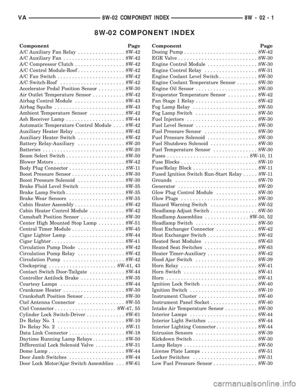
8W-02 COMPONENT INDEX
Component Page
A/C Auxiliary Fan Relay................ 8W-42
A/C Auxiliary Fan..................... 8W-42
A/C Compressor Clutch................. 8W-42
A/C Control Module-Roof................ 8W-42
A/C Fan Switch....................... 8W-42
A/C Switch-Roof...................... 8W-42
Accelerator Pedal Position Sensor......... 8W-30
Air Outlet Temperature Sensor........... 8W-42
Airbag Control Module................. 8W-43
Airbag Squibs........................ 8W-43
Ambient Temperature Sensor............ 8W-42
Ash Receiver Lamp.................... 8W-44
Automatic Temperature Control Module.... 8W-42
Auxiliary Heater Relay................. 8W-42
Auxiliary Heater Switch................ 8W-42
Battery Relay-Auxiliary................ 8W-20
Batteries............................ 8W-20
Beam Select Switch.................... 8W-50
Blower Motors........................ 8W-42
Body Plug Connector................... 8W-11
Boost Pressure Sensor.................. 8W-30
Boost Pressure Solenoid................ 8W-30
Brake Fluid Level Switch............... 8W-35
Brake Lamp Switch.................... 8W-35
Brake Wear Sensors................... 8W-35
Cabin Heater Assembly................. 8W-42
Cabin Heater Control Module............ 8W-42
Camshaft Position Sensor............... 8W-30
Center High Mounted Stop Lamp......... 8W-51
Central Timer Module.................. 8W-45
Cigar Lighter Lamp................... 8W-44
Cigar Lighter......................... 8W-41
Circulation Pump Diode................ 8W-42
Circulation Pump Relay................ 8W-42
Circulation Pump..................... 8W-42
Clockspring....................... 8W-41, 43
Contact Switch Door-Tailgate............ 8W-44
Controller Antilock Brake............... 8W-35
Courtesy Lamps...................... 8W-44
Crankcase Heater..................... 8W-30
Crankshaft Position Sensor.............. 8W-30
Ctel Antenna Connector................ 8W-55
Ctel Connector..................... 8W-47, 55
Cylinder Lock Switch-Driver............. 8W-61
D+ Relay No. 1....................... 8W-10
D+ Relay No. 2....................... 8W-11
Data Link Connector................... 8W-18
Daytime Running Lamp Relays........... 8W-50
Differential Lock Solenoid Valve.......... 8W-31
Dome Lamp.......................... 8W-44
Door Jamb Switches................... 8W-44
Door Lock Motor/Ajar Switch Assemblies . . . 8W-61Component Page
Dosing Pump......................... 8W-42
EGR Valve........................... 8W-30
Engine Control Module................. 8W-30
Engine Control Relay.................. 8W-31
Engine Coolant Level Switch............. 8W-30
Engine Coolant Temperature Sensor....... 8W-30
Engine Oil Sensor..................... 8W-30
Evaporator Temperature Sensor.......... 8W-42
Fan Stage 1 Relay..................... 8W-42
Fog Lamp Relay...................... 8W-50
Fog Lamp Switch..................... 8W-50
Fuel Injectors........................ 8W-30
Fuel Level Sensor..................... 8W-30
Fuel Pressure Sensor.................. 8W-30
Fuel Pressure Solenoid................. 8W-30
Fuel Shutdown Solenoid................ 8W-30
Fuel Temperature Sensor............... 8W-30
Fuses............................ 8W-10, 11
Fuse Blocks.......................... 8W-10
Fuse/Relay Block...................... 8W-11
Fused Ignition Switch Run-Start Relay..... 8W-11
Grounds............................ 8W-70
Generator........................... 8W-20
Glow Plug Control Module.............. 8W-30
Glow Plugs.......................... 8W-30
Hazard Warning Switch................ 8W-52
Headlamp Adjust Switch................ 8W-50
Headlamp Assemblies............... 8W-50, 52
Headlamp Switch..................... 8W-50
Heat Exchanger Connector.............. 8W-42
Heat Exchanger Switch................. 8W-42
Heated Seat Modules.................. 8W-63
Heated Seat Switches.................. 8W-63
Heater Timer-Auxiliary................. 8W-42
Hood Ajar Switch..................... 8W-39
Horn Relay.......................... 8W-41
Horn Switch......................... 8W-41
Horn............................... 8W-41
Ignition Lock Switch................... 8W-40
Ignition Switch....................... 8W-10
Instrument Cluster.................... 8W-40
Instrument Panel Socket................ 8W-40
Intake Air Temperature Sensor........... 8W-30
Interior Lamps....................... 8W-44
Interior Light Switches................. 8W-44
Interior Lighting Connector.............. 8W-44
Intrusion Sensors..................... 8W-39
Kickdown Switch...................... 8W-30
Lamp Relays......................... 8W-50
License Plate Lamps................... 8W-51
Locker Switches...................... 8W-31
Low Fuel Pressure Sensor............... 8W-30
VA8W-02 COMPONENT INDEX 8W - 02 - 1
Page 318 of 1232
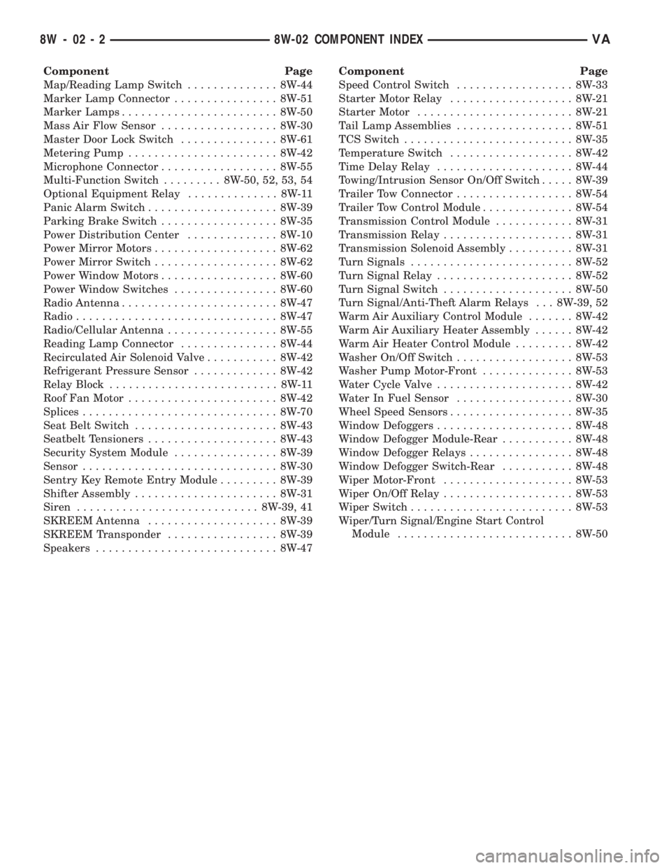
Component Page
Map/Reading Lamp Switch.............. 8W-44
Marker Lamp Connector................ 8W-51
Marker Lamps........................ 8W-50
Mass Air Flow Sensor.................. 8W-30
Master Door Lock Switch............... 8W-61
Metering Pump....................... 8W-42
Microphone Connector.................. 8W-55
Multi-Function Switch......... 8W-50, 52, 53, 54
Optional Equipment Relay.............. 8W-11
Panic Alarm Switch.................... 8W-39
Parking Brake Switch.................. 8W-35
Power Distribution Center.............. 8W-10
Power Mirror Motors................... 8W-62
Power Mirror Switch................... 8W-62
Power Window Motors.................. 8W-60
Power Window Switches................ 8W-60
Radio Antenna........................ 8W-47
Radio............................... 8W-47
Radio/Cellular Antenna................. 8W-55
Reading Lamp Connector............... 8W-44
Recirculated Air Solenoid Valve........... 8W-42
Refrigerant Pressure Sensor............. 8W-42
Relay Block.......................... 8W-11
Roof Fan Motor....................... 8W-42
Splices.............................. 8W-70
Seat Belt Switch...................... 8W-43
Seatbelt Tensioners.................... 8W-43
Security System Module................ 8W-39
Sensor.............................. 8W-30
Sentry Key Remote Entry Module......... 8W-39
Shifter Assembly...................... 8W-31
Siren............................ 8W-39, 41
SKREEM Antenna.................... 8W-39
SKREEM Transponder................. 8W-39
Speakers............................ 8W-47Component Page
Speed Control Switch.................. 8W-33
Starter Motor Relay................... 8W-21
Starter Motor........................ 8W-21
Tail Lamp Assemblies.................. 8W-51
TCS Switch.......................... 8W-35
Temperature Switch................... 8W-42
Time Delay Relay..................... 8W-44
Towing/Intrusion Sensor On/Off Switch..... 8W-39
Trailer Tow Connector.................. 8W-54
Trailer Tow Control Module.............. 8W-54
Transmission Control Module............ 8W-31
Transmission Relay.................... 8W-31
Transmission Solenoid Assembly.......... 8W-31
Turn Signals......................... 8W-52
Turn Signal Relay..................... 8W-52
Turn Signal Switch.................... 8W-50
Turn Signal/Anti-Theft Alarm Relays . . . 8W-39, 52
Warm Air Auxiliary Control Module....... 8W-42
Warm Air Auxiliary Heater Assembly...... 8W-42
Warm Air Heater Control Module......... 8W-42
Washer On/Off Switch.................. 8W-53
Washer Pump Motor-Front.............. 8W-53
Water Cycle Valve..................... 8W-42
Water In Fuel Sensor.................. 8W-30
Wheel Speed Sensors................... 8W-35
Window Defoggers..................... 8W-48
Window Defogger Module-Rear........... 8W-48
Window Defogger Relays................ 8W-48
Window Defogger Switch-Rear........... 8W-48
Wiper Motor-Front.................... 8W-53
Wiper On/Off Relay.................... 8W-53
Wiper Switch......................... 8W-53
Wiper/Turn Signal/Engine Start Control
Module........................... 8W-50
8W - 02 - 2 8W-02 COMPONENT INDEXVA
Page 319 of 1232
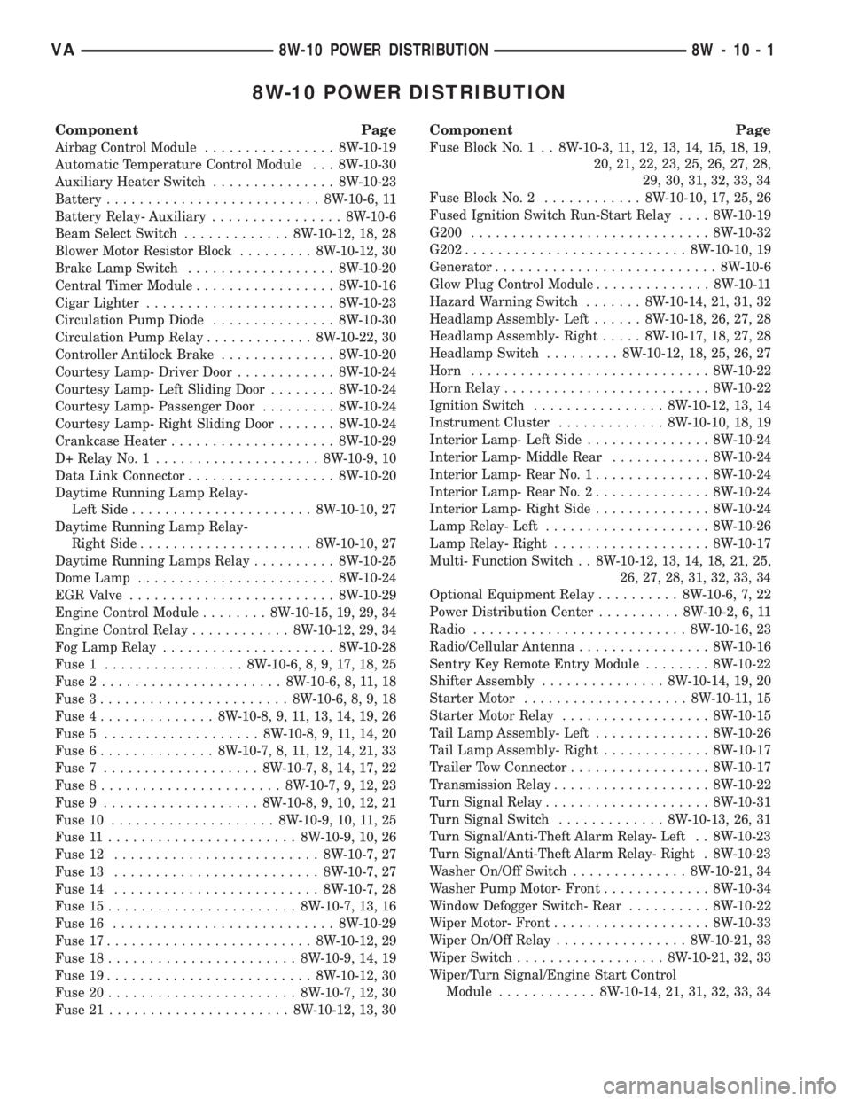
8W-10 POWER DISTRIBUTION
Component Page
Airbag Control Module................ 8W-10-19
Automatic Temperature Control Module . . . 8W-10-30
Auxiliary Heater Switch............... 8W-10-23
Battery.......................... 8W-10-6, 11
Battery Relay- Auxiliary................ 8W-10-6
Beam Select Switch............. 8W-10-12, 18, 28
Blower Motor Resistor Block......... 8W-10-12, 30
Brake Lamp Switch.................. 8W-10-20
Central Timer Module................. 8W-10-16
Cigar Lighter....................... 8W-10-23
Circulation Pump Diode............... 8W-10-30
Circulation Pump Relay............. 8W-10-22, 30
Controller Antilock Brake.............. 8W-10-20
Courtesy Lamp- Driver Door............ 8W-10-24
Courtesy Lamp- Left Sliding Door........ 8W-10-24
Courtesy Lamp- Passenger Door......... 8W-10-24
Courtesy Lamp- Right Sliding Door....... 8W-10-24
Crankcase Heater.................... 8W-10-29
D+ Relay No. 1.................... 8W-10-9, 10
Data Link Connector.................. 8W-10-20
Daytime Running Lamp Relay-
Left Side...................... 8W-10-10, 27
Daytime Running Lamp Relay-
Right Side..................... 8W-10-10, 27
Daytime Running Lamps Relay.......... 8W-10-25
Dome Lamp........................ 8W-10-24
EGR Valve......................... 8W-10-29
Engine Control Module........ 8W-10-15, 19, 29, 34
Engine Control Relay............ 8W-10-12, 29, 34
Fog Lamp Relay..................... 8W-10-28
Fuse 1................. 8W-10-6, 8, 9, 17, 18, 25
Fuse 2...................... 8W-10-6, 8, 11, 18
Fuse 3....................... 8W-10-6, 8, 9, 18
Fuse 4.............. 8W-10-8, 9, 11, 13, 14, 19, 26
Fuse 5................... 8W-10-8, 9, 11, 14, 20
Fuse 6.............. 8W-10-7, 8, 11, 12, 14, 21, 33
Fuse 7................... 8W-10-7, 8, 14, 17, 22
Fuse 8...................... 8W-10-7, 9, 12, 23
Fuse 9................... 8W-10-8, 9, 10, 12, 21
Fuse 10.................... 8W-10-9, 10, 11, 25
Fuse 11....................... 8W-10-9, 10, 26
Fuse 12......................... 8W-10-7, 27
Fuse 13......................... 8W-10-7, 27
Fuse 14......................... 8W-10-7, 28
Fuse 15....................... 8W-10-7, 13, 16
Fuse 16........................... 8W-10-29
Fuse 17......................... 8W-10-12, 29
Fuse 18....................... 8W-10-9, 14, 19
Fuse 19......................... 8W-10-12, 30
Fuse 20....................... 8W-10-7, 12, 30
Fuse 21...................... 8W-10-12, 13, 30
Component Page
Fuse Block No. 1 . . 8W-10-3, 11, 12, 13, 14, 15, 18, 19,
20, 21, 22, 23, 25, 26, 27, 28,
29, 30, 31, 32, 33, 34
Fuse Block No. 2............ 8W-10-10, 17, 25, 26
Fused Ignition Switch Run-Start Relay.... 8W-10-19
G200............................. 8W-10-32
G202........................... 8W-10-10, 19
Generator........................... 8W-10-6
Glow Plug Control Module.............. 8W-10-11
Hazard Warning Switch....... 8W-10-14, 21, 31, 32
Headlamp Assembly- Left...... 8W-10-18, 26, 27, 28
Headlamp Assembly- Right..... 8W-10-17, 18, 27, 28
Headlamp Switch......... 8W-10-12, 18, 25, 26, 27
Horn............................. 8W-10-22
Horn Relay......................... 8W-10-22
Ignition Switch................ 8W-10-12, 13, 14
Instrument Cluster............. 8W-10-10, 18, 19
Interior Lamp- Left Side............... 8W-10-24
Interior Lamp- Middle Rear............ 8W-10-24
Interior Lamp- Rear No. 1.............. 8W-10-24
Interior Lamp- Rear No. 2.............. 8W-10-24
Interior Lamp- Right Side.............. 8W-10-24
Lamp Relay- Left.................... 8W-10-26
Lamp Relay- Right................... 8W-10-17
Multi- Function Switch . . 8W-10-12, 13, 14, 18, 21, 25,
26, 27, 28, 31, 32, 33, 34
Optional Equipment Relay.......... 8W-10-6, 7, 22
Power Distribution Center.......... 8W-10-2, 6, 11
Radio.......................... 8W-10-16, 23
Radio/Cellular Antenna................ 8W-10-16
Sentry Key Remote Entry Module........ 8W-10-22
Shifter Assembly............... 8W-10-14, 19, 20
Starter Motor.................... 8W-10-11, 15
Starter Motor Relay.................. 8W-10-15
Tail Lamp Assembly- Left.............. 8W-10-26
Tail Lamp Assembly- Right............. 8W-10-17
Trailer Tow Connector................. 8W-10-17
Transmission Relay................... 8W-10-22
Turn Signal Relay.................... 8W-10-31
Turn Signal Switch............. 8W-10-13, 26, 31
Turn Signal/Anti-Theft Alarm Relay- Left . . 8W-10-23
Turn Signal/Anti-Theft Alarm Relay- Right . 8W-10-23
Washer On/Off Switch.............. 8W-10-21, 34
Washer Pump Motor- Front............. 8W-10-34
Window Defogger Switch- Rear.......... 8W-10-22
Wiper Motor- Front................... 8W-10-33
Wiper On/Off Relay................ 8W-10-21, 33
Wiper Switch.................. 8W-10-21, 32, 33
Wiper/Turn Signal/Engine Start Control
Module............ 8W-10-14, 21, 31, 32, 33, 34
VA8W-10 POWER DISTRIBUTION 8W - 10 - 1