2005 MERCEDES-BENZ SPRINTER steering
[x] Cancel search: steeringPage 700 of 1232
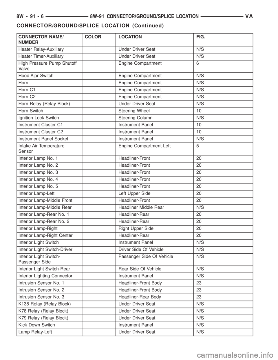
CONNECTOR NAME/
NUMBERCOLOR LOCATION FIG.
Heater Relay-Auxiliary Under Driver Seat N/S
Heater Timer-Auxiliary Under Driver Seat N/S
High Pressure Pump Shutoff
ValveEngine Compartment 6
Hood Ajar Switch Engine Compartment N/S
Horn Engine Compartment N/S
Horn C1 Engine Compartment N/S
Horn C2 Engine Compartment N/S
Horn Relay (Relay Block) Under Driver Seat N/S
Horn-Switch Steering Wheel 10
Ignition Lock Switch Steering Column N/S
Instrument Cluster C1 Instrument Panel 10
Instrument Cluster C2 Instrument Panel 10
Instrument Panel Socket Instrument Panel N/S
Intake Air Temperature
SensorEngine Compartment-Left 5
Interior Lamp No. 1 Headliner-Front 20
Interior Lamp No. 2 Headliner-Front 20
Interior Lamp No. 3 Headliner-Front 20
Interior Lamp No. 4 Headliner-Front 20
Interior Lamp No. 5 Headliner-Front 20
Interior Lamp-Left Left Upper Side 20
Interior Lamp-Middle Front Headliner-Front 20
Interior Lamp-Middle Rear Headliner Middle Rear N/S
Interior Lamp-Rear No. 1 Headliner-Rear 20
Interior Lamp-Rear No. 2 Headliner-Rear 20
Interior Lamp-Right Right Upper Side 20
Interior Lamp-Right Center Headliner-Rear 20
Interior Light Switch Instrument Panel N/S
Interior Light Switch-Driver Driver Side Of Vehicle N/S
Interior Light Switch-
Passenger SidePassenger Side Of Vehicle N/S
Interior Light Switch-Rear Rear Side Of Vehicle N/S
Interior Lighting Connector Instrument Panel N/S
Intrusion Sensor No. 1 Headliner-Front Body 23
Intrusion Sensor No. 2 Headliner-Front Body 23
Intrusion Sensor No. 3 Headliner-Rear Body 23
K138 Relay (Relay Block) Under Driver Seat N/S
K78 Relay (Relay Block) Under Driver Seat N/S
K79 Relay (Relay Block) Under Driver Seat N/S
Kick Down Switch Instrument Panel N/S
Lamp Relay-Left Under Driver Seat N/S
8W - 91 - 6 8W-91 CONNECTOR/GROUND/SPLICE LOCATIONVA
CONNECTOR/GROUND/SPLICE LOCATION (Continued)
Page 701 of 1232
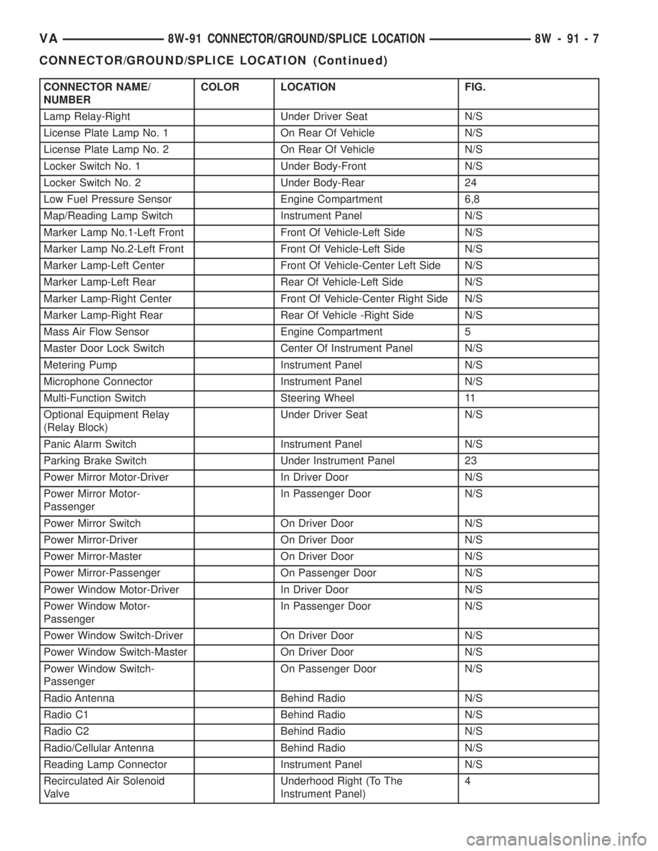
CONNECTOR NAME/
NUMBERCOLOR LOCATION FIG.
Lamp Relay-Right Under Driver Seat N/S
License Plate Lamp No. 1 On Rear Of Vehicle N/S
License Plate Lamp No. 2 On Rear Of Vehicle N/S
Locker Switch No. 1 Under Body-Front N/S
Locker Switch No. 2 Under Body-Rear 24
Low Fuel Pressure Sensor Engine Compartment 6,8
Map/Reading Lamp Switch Instrument Panel N/S
Marker Lamp No.1-Left Front Front Of Vehicle-Left Side N/S
Marker Lamp No.2-Left Front Front Of Vehicle-Left Side N/S
Marker Lamp-Left Center Front Of Vehicle-Center Left Side N/S
Marker Lamp-Left Rear Rear Of Vehicle-Left Side N/S
Marker Lamp-Right Center Front Of Vehicle-Center Right Side N/S
Marker Lamp-Right Rear Rear Of Vehicle -Right Side N/S
Mass Air Flow Sensor Engine Compartment 5
Master Door Lock Switch Center Of Instrument Panel N/S
Metering Pump Instrument Panel N/S
Microphone Connector Instrument Panel N/S
Multi-Function Switch Steering Wheel 11
Optional Equipment Relay
(Relay Block)Under Driver Seat N/S
Panic Alarm Switch Instrument Panel N/S
Parking Brake Switch Under Instrument Panel 23
Power Mirror Motor-Driver In Driver Door N/S
Power Mirror Motor-
PassengerIn Passenger Door N/S
Power Mirror Switch On Driver Door N/S
Power Mirror-Driver On Driver Door N/S
Power Mirror-Master On Driver Door N/S
Power Mirror-Passenger On Passenger Door N/S
Power Window Motor-Driver In Driver Door N/S
Power Window Motor-
PassengerIn Passenger Door N/S
Power Window Switch-Driver On Driver Door N/S
Power Window Switch-Master On Driver Door N/S
Power Window Switch-
PassengerOn Passenger Door N/S
Radio Antenna Behind Radio N/S
Radio C1 Behind Radio N/S
Radio C2 Behind Radio N/S
Radio/Cellular Antenna Behind Radio N/S
Reading Lamp Connector Instrument Panel N/S
Recirculated Air Solenoid
ValveUnderhood Right (To The
Instrument Panel)4
VA8W-91 CONNECTOR/GROUND/SPLICE LOCATION 8W - 91 - 7
CONNECTOR/GROUND/SPLICE LOCATION (Continued)
Page 702 of 1232
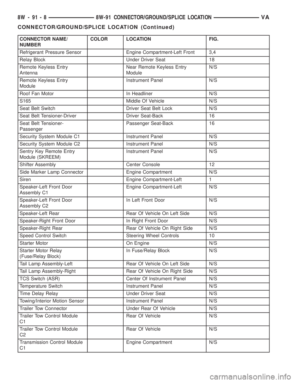
CONNECTOR NAME/
NUMBERCOLOR LOCATION FIG.
Refrigerant Pressure Sensor Engine Compartment-Left Front 3,4
Relay Block Under Driver Seat 18
Remote Keyless Entry
AntennaNear Remote Keyless Entry
ModuleN/S
Remote Keyless Entry
ModuleInstrument Panel N/S
Roof Fan Motor In Headliner N/S
S165 Middle Of Vehicle N/S
Seat Belt Switch Driver Seat Belt Lock N/S
Seat Belt Tensioner-Driver Driver Seat-Back 16
Seat Belt Tensioner-
PassengerPassenger Seat-Back 16
Security System Module C1 Instrument Panel N/S
Security System Module C2 Instrument Panel N/S
Sentry Key Remote Entry
Module (SKREEM)Instrument Panel N/S
Shifter Assembly Center Console 12
Side Marker Lamp Connector Engine Compartment N/S
Siren Engine Compartment-Left 1
Speaker-Left Front Door
Assembly C1Engine Compartment-Left N/S
Speaker-Left Front Door
Assembly C2In Left Front Door N/S
Speaker-Left Rear Rear Of Vehicle On Left Side N/S
Speaker-Right Front Door In Right Front Door N/S
Speaker-Right Rear Rear Of Vehicle On Right Side N/S
Speed Control Switch Steering Wheel Controls 10
Starter Motor On Engine N/S
Starter Motor Relay
(Fuse/Relay Block)In Fuse/Relay Block N/S
Tail Lamp Assembly-Left Rear Of Vehicle On Left Side N/S
Tail Lamp Assembly-Right Rear Of Vehicle On Right Side N/S
TCS Switch (ASR) Center Of Instrument Panel N/S
Temperature Switch Instrument Panel N/S
Time Delay Relay Under Driver Seat N/S
Towing/Interior Motion Sensor Instrument Panel N/S
Trailer Tow Connector Under Rear Of Vehicle N/S
Trailer Tow Control Module
C1Rear Of Vehicle N/S
Trailer Tow Control Module
C2Rear Of Vehicle N/S
Transmission Control Module
C1Engine Compartment N/S
8W - 91 - 8 8W-91 CONNECTOR/GROUND/SPLICE LOCATIONVA
CONNECTOR/GROUND/SPLICE LOCATION (Continued)
Page 734 of 1232
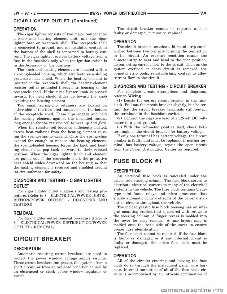
OPERATION
The cigar lighter consists of two major components:
a knob and heating element unit, and the cigar
lighter base or receptacle shell. The receptacle shell
is connected to ground, and an insulated contact in
the bottom of the shell is connected to battery cur-
rent. The cigar lighter receives battery voltage from a
fuse in the fuseblock only when the ignition switch is
in the Accessory or On positions.
The knob and heating element are encased within
a spring-loaded housing, which also features a sliding
protective heat shield. When the heating element is
inserted in the receptacle shell, the heating element
resistor coil is grounded through its housing to the
receptacle shell. If the cigar lighter knob is pushed
inward, the heat shield slides up toward the knob
exposing the heating element.
Two small spring-clip retainers are located on
either side of the insulated contact inside the bottom
of the receptacle shell. These clips engage and hold
the heating element against the insulated contact
long enough for the resistor coil to heat up and glow.
When the resistor coil becomes sufficiently heated,
excess heat radiates from the heating element caus-
ing the spring-clips to expand. Once the spring-clips
expand far enough to release the heating element,
the spring-loaded housing forces the knob and heat-
ing element to pop back outward to their relaxed
position. When the cigar lighter knob and element
are pulled out of the receptacle shell, the protective
heat shield slides downward on the housing so that
the heating element is recessed and shielded around
its circumference for safety.
DIAGNOSIS AND TESTING - CIGAR LIGHTER
OUTLET
For cigar lighter outlet diagnosis and testing pro-
cedures (Refer to 8 - ELECTRICAL/POWER DISTRI-
BUTION/POWER OUTLET - DIAGNOSIS AND
TESTING)
REMOVAL
For cigar lighter outlet removal procedure (Refer to
8 - ELECTRICAL/POWER DISTRIBUTION/POWER
OUTLET - REMOVAL).
CIRCUIT BREAKER
DESCRIPTION
Automatic resetting circuit breakers are used to
protect the power window voltage supply circuits.
These circuit breakers can protect the systems from a
short circuit, or from an overload condition caused by
an obstructed or stuck power window regulator or
switch.The circuit breaker cannot be repaired and, if
faulty or damaged, it must be replaced.
OPERATION
The circuit breaker contains a bi-metal strip sand-
wiched between two contacts forming the connection
in the circuit. An overload condition causes the
bi-metal strip to heat and bend to the open position,
disconnecting current flow to the circuit. Then as the
system overload or short circuit is removed, the
bi-metal strip cools, re-establishing contact to allow
current flow to the circuit.
DIAGNOSIS AND TESTING - CIRCUIT BREAKER
For complete circuit descriptions and diagrams,
refer toWiring.
(1) Locate the correct circuit breaker in the fuse-
block. Pull out the circuit breaker slightly, but be cer-
tain that the circuit breaker terminals still contact
the terminals in the fuseblock cavities.
(2) Connect the negative lead of a 12-volt DC volt-
meter to a good ground.
(3) With the voltmeter positive lead, check both
terminals of the circuit breaker for battery voltage.
If only one terminal has battery voltage, the circuit
breaker is faulty and must be replaced. If neither ter-
minal has battery voltage, repair the open circuit
from the Power Distribution Center as required.
FUSE BLOCK #1
DESCRIPTION
An electrical fuse block is concealed under the
driver side steering column. The fuse block serves to
distribute electrical current to many of the electrical
systems in the vehicle. The fuse block contains blade-
type mini fuses, relays and micro processors that
enable automatic control of some of the power distri-
bution circuits throughout the vehicle.
The molded plastic fuse block housing has an inte-
gral mounting bracket that is secured with screws to
the steering column. A finger recess is molded into
the cover for easy removal. A fuse layout map is
molded onto the back side of the cover to ensure
proper fuse identification.
The fuse block cannot be repaired, if the fuse block
is faulty or damaged or if any internal circuit is
faulty or damaged, the entire fuse block must be
replaced.
OPERATION
All of the circuits entering and leaving the fuse
block do so through the instrument panel wire har-
ness. Internal connection of all of the fuse block cir-
cuits is accomplished by an intricate combination of
8W - 97 - 2 8W-97 POWER DISTRIBUTIONVA
CIGAR LIGHTER OUTLET (Continued)
Page 735 of 1232
hard wiring and bus bars. Internal relays and micro
processors allow the vehicle electronics to control
some of the power distribution circuits throughout
the vehicle. Refer to the Wiring section for complete
circuit diagrams.
REMOVAL
(1) Disconnect and isolate the negative battery
cable.
(2) Remove fuse block cover by rotating locking
screw 90É.
(3) Remove the steering column cover. Refer to the
Body section for the procedure.
(4) Unscrew fuse block connections and disconnect
all electrical connectors from the fuse block.
(5) Remove the fuse block from the steering col-
umn.
INSTALLATION
(1) Position the fuse block in the steering column.
(2) Install fuse block connections and connect all
electrical connectors on the fuse block.
(3) Install the steering column cover. Refer to the
Body section for the procedure.
(4) Install fuse block cover by rotating locking
screw 90É.
(5) Connect the negative battery cable.
(6) Set time and radio stations.
FUSE BLOCK #2
DESCRIPTION
An electrical fuse block is concealed under the
driver side front seat. The fuse block serves to dis-
tribute electrical current to many of the electrical
systems in the vehicle. The fuse block houses blade-
type mini fuses, blade-type automatic resetting cir-
cuit breakers and International Standards
Organization relays. Additional provisions are avail-
able in the fuse block for additional fuses and ISO
relays.
The molded plastic fuse block housing has an inte-
gral mounting bracket that is secured with screws to
the seat base. The driver side seat base also has a
snap-fit fuse access panel that can be removed for
service of the fuses and the relays. A finger recess is
molded into one end for easy removal. A fuse layout
map is molded onto the back side of the panel to
ensure proper fuse identification.
The fuse block is integral to the body wire harness.
If any internal circuit or the fuse block housing is
faulty or damaged, the entire fuse block and body
wire harness unit must be replaced.
OPERATION
All of the circuits entering and leaving the fuse
block do so through the body wire harness. Internal
connection of all of the fuse block circuits is accom-
plished by an intricate combination of hard wiring
and bus bars.
POWER DISTRIBUTION
CENTER
DESCRIPTION
All of the electrical current distributed throughout
this vehicle is directed through the Power Distribu-
tion Center (PDC). The molded plastic PDC housing
is located in the left front corner of the engine com-
partment, on the battery positive cable. The PDC
housing has a molded plastic cover that slides over
the PDC housing. The PDC cover is easily opened or
removed for service access.
The PDC unit cannot be repaired and is only ser-
viced as a unit with the headlamp and dash wire
harness. If the internal circuits or the PDC housing
are faulty or damaged, the headlamp and dash wire
harness unit must be replaced.
OPERATION
All of the current from the battery and the gener-
ator output enters the PDC through the positive bat-
tery cable. The PDC cover is removed to access the
battery and generator output connection B(+) termi-
nal studs. Internal connection of all of the PDC cir-
cuits is accomplished by an intricate combination of
hard wiring and bus bars. Refer to Wiring Diagrams
for the location of complete PDC circuit diagrams.
POWER OUTLET
DESCRIPTION
The power outlet is installed in the instrument
panel accessory switch plate, which is located near
the center of the instrument panel. The power outlet
base is secured by a snap fit within the instrument
panel. A plastic protective cap snaps over the power
outlet base when the power outlet is not being used.
While the power outlet is very similar to a cigar
lighter base unit, it does not include the two small
spring-clip retainers inside the bottom of the recepta-
cle shell that are used to secure the cigar lighter
heating element to the insulated contact.
The power outlet receptacle unit are available for
service. The power outlet receptacle cannot be
repaired and, if faulty or damaged, it must be
replaced.
VA8W-97 POWER DISTRIBUTION 8W - 97 - 3
FUSE BLOCK #1 (Continued)
Page 743 of 1232
(2) Remove the hood.
(3) Drain cooling system (Refer to 7 - COOLING/
ENGINE/COOLANT - STANDARD PROCEDURE).
(4) Evacuate and recover air conditioning system
(Refer to 24 - HEATING & AIR CONDITIONING/
PLUMBING - STANDARD PROCEDURE).
(5) Disconnect the engine wiring harness at the
vehicle side and carefully guide though the cowl into
the engine area.
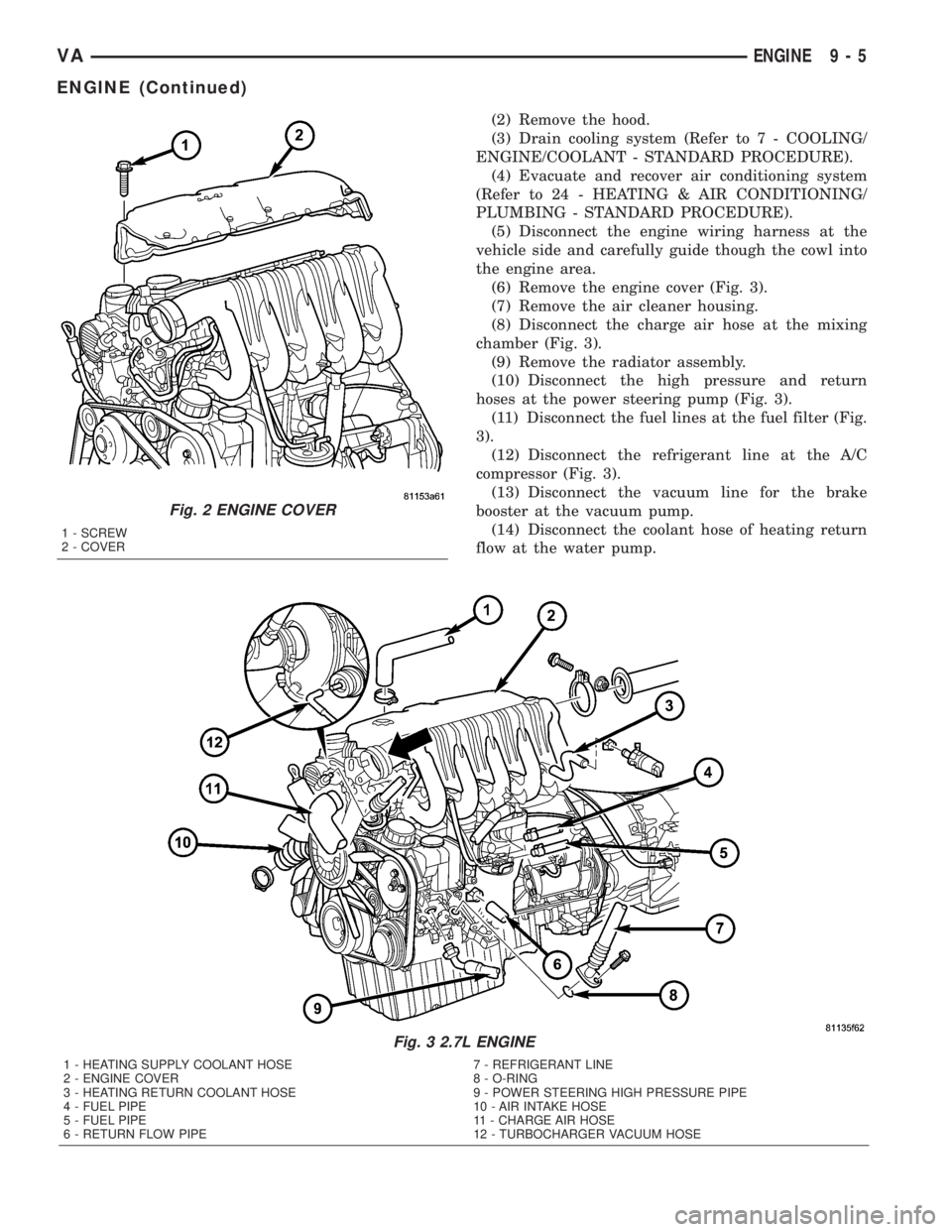
(6) Remove the engine cover (Fig. 3).
(7) Remove the air cleaner housing.
(8) Disconnect the charge air hose at the mixing
chamber (Fig. 3).
(9) Remove the radiator assembly.
(10) Disconnect the high pressure and return
hoses at the power steering pump (Fig. 3).
(11) Disconnect the fuel lines at the fuel filter (Fig.
3).
(12) Disconnect the refrigerant line at the A/C
compressor (Fig. 3).
(13) Disconnect the vacuum line for the brake
booster at the vacuum pump.
(14) Disconnect the coolant hose of heating return
flow at the water pump.
Fig. 3 2.7L ENGINE
1 - HEATING SUPPLY COOLANT HOSE 7 - REFRIGERANT LINE
2 - ENGINE COVER 8 - O-RING
3 - HEATING RETURN COOLANT HOSE 9 - POWER STEERING HIGH PRESSURE PIPE
4 - FUEL PIPE 10 - AIR INTAKE HOSE
5 - FUEL PIPE 11 - CHARGE AIR HOSE
6 - RETURN FLOW PIPE 12 - TURBOCHARGER VACUUM HOSE
Fig. 2 ENGINE COVER
1 - SCREW
2 - COVER
VAENGINE 9 - 5
ENGINE (Continued)
Page 744 of 1232
(15) Disconnect the coolant hose of the heater sup-
ply at the coolant pipe at the side of the cylinder
head (Fig. 3).
(16) Disconnect the vacuum hose at the turbo-
charger (Fig. 3).
(17) Disconnect the air inlet hose at the turbo-
charger (Fig. 3).
(18) Raise and support the vehicle.
(19) Disconnect the front exhaust at the turbo-
charger.
(20) Disconnect the electrical connector at the
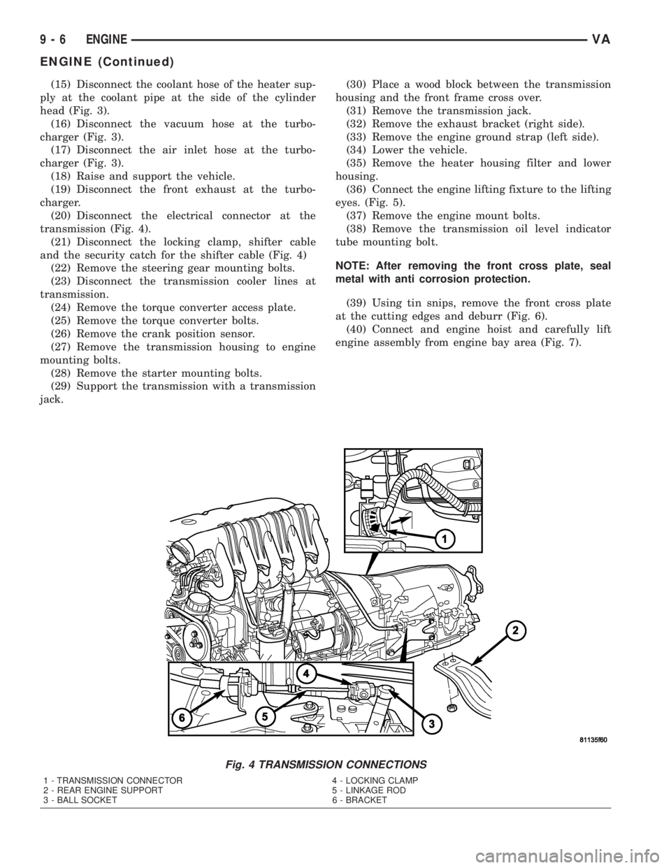
transmission (Fig. 4).
(21) Disconnect the locking clamp, shifter cable
and the security catch for the shifter cable (Fig. 4)
(22) Remove the steering gear mounting bolts.
(23) Disconnect the transmission cooler lines at
transmission.
(24) Remove the torque converter access plate.
(25) Remove the torque converter bolts.
(26) Remove the crank position sensor.
(27) Remove the transmission housing to engine
mounting bolts.
(28) Remove the starter mounting bolts.
(29) Support the transmission with a transmission
jack.(30) Place a wood block between the transmission
housing and the front frame cross over.
(31) Remove the transmission jack.
(32) Remove the exhaust bracket (right side).
(33) Remove the engine ground strap (left side).
(34) Lower the vehicle.
(35) Remove the heater housing filter and lower
housing.
(36) Connect the engine lifting fixture to the lifting
eyes. (Fig. 5).
(37) Remove the engine mount bolts.
(38) Remove the transmission oil level indicator
tube mounting bolt.
NOTE: After removing the front cross plate, seal
metal with anti corrosion protection.
(39) Using tin snips, remove the front cross plate
at the cutting edges and deburr (Fig. 6).
(40) Connect and engine hoist and carefully lift
engine assembly from engine bay area (Fig. 7).
Fig. 4 TRANSMISSION CONNECTIONS
1 - TRANSMISSION CONNECTOR 4 - LOCKING CLAMP
2 - REAR ENGINE SUPPORT 5 - LINKAGE ROD
3 - BALL SOCKET 6 - BRACKET
9 - 6 ENGINEVA
ENGINE (Continued)
Page 746 of 1232
(11) Install the transmission cooler lines to trans-
mission.(Refer to 21 - TRANSMISSION/TRANS-
AXLE/AUTOMATIC - NAG1 - INSTALLATION) for
correct sequence and torque specification.
(12) Install transmission electrical connector and
shifter hardware.Refer to (Refer to 21 - TRANSMIS-
SION/TRANSAXLE/AUTOMATIC - NAG1 - INSTAL-
LATION) for correct sequence and torque
specification.
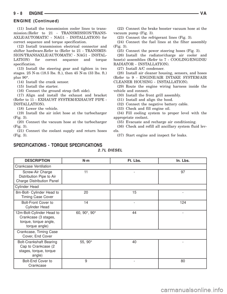
(13) Install the steering gear and tighten in two
stages. 25 N´m (18.5 lbs. ft.), then 45 N´m (33 lbs. ft.)
plus 90É.
(14) Install the crank sensor.
(15) Install the starter.
(16) Connect the ground strap (left side).
(17) Align and install the exhaust and bracket
(Refer to 11 - EXHAUST SYSTEM/EXHAUST PIPE -
INSTALLATION).
(18) Lower the vehicle.
(19) Install the air inlet hose at the turbocharger
(Fig. 3).
(20) Connect the vacuum hose at the turbocharger
(Fig. 3).
(21) Connect the coolant supply and return hoses
(Fig. 3).(22) Connect the brake booster vacuum hose at the
vacuum pump (Fig. 3).
(23) Connect the refrigerant lines (Fig. 3).
(24) Connect the fuel lines at the filter assembly
(Fig. 3).
(25) Connect the power steering hoses (Fig. 3).
(26) Install the radiator/charge air cooler and
hose(s) assemblies (Refer to 7 - COOLING/ENGINE/
RADIATOR - INSTALLATION).
(27) Install A/C condenser.
(28) Install air cleaner housing, sensors, and hoses
(Refer to 9 - ENGINE/AIR INTAKE SYSTEM/AIR
CLEANER HOUSING - INSTALLATION).
(29) Route the engine wiring harness inside the
vehicle and connect.
(30) Install the front grill assembly.
(31) Install and align the hood.
(32) Connect the negative battery cable.
(33) Check and fill engine oil.
(34) Fill cooling system to proper level with the
appropriate coolant.
(35) Evacuate and recharge air conditioning.
(36) Check and refill all ancillary system fluid lev-
els.
(37) Start engine and inspect for leaks.
SPECIFICATIONS - TORQUE SPECIFICATIONS
2.7L DIESEL
DESCRIPTION N´m Ft. Lbs. In. Lbs.
Crankcase Ventilation
Screw-Air Charge
Distribution Pipe to Air
Charge Distribution Panel11 - 9 7
Cylinder Head
8m-Bolt- Cylinder Head to
Timing Case Cover20 15 -
Bolt-Front Cover to
Cylinder Head14 - 124
12m-Bolt-Cylinder Head to
Crankcase (3 stages,
torque, torque angle,
torque angle)60, 90É, 90É 44 -
Crankcase, Timing Case
Cover, End Cover
Bolt-Crankshaft Bearing
Cap to Crankcase (2
stages, torque, torque
angle)55, 90É 40 -
Bolt-End Cover to
Crankcase9-80
9 - 8 ENGINEVA
ENGINE (Continued)