2005 MERCEDES-BENZ SPRINTER steering
[x] Cancel search: steeringPage 852 of 1232
WARNING: NO SPARKS, OPEN FLAMES OR SMOK-
ING. RISK OF POISONING FROM INHALING AND
SWALLOWING FUEL. RISK OF INJURY TO EYES
AND SKIN FROM CONTACT WITH FUEL. POUR
FUELS ONLY INTO SUITABLE AND APPROPRI-
ATELY MARKED CONTAINERS. WEAR PROTECTIVE
CLOTHING.
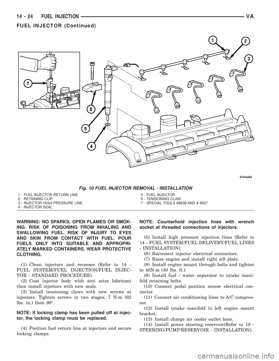
(1) Clean injectors and recesses (Refer to 14 -
FUEL SYSTEM/FUEL INJECTION/FUEL INJEC-
TOR - STANDARD PROCEDURE).
(2) Coat injector body with anti seize lubricant
then install injectors with new seals.
(3) Install tensioning claws with new screws at
injectors. Tighten screws in two stages, 7 N´m (62
lbs. in.) then 90É.
NOTE: If locking clamp has been pulled off at injec-
tor, the locking clamp must be replaced.
(4) Position fuel return line at injectors and secure
locking clamps.NOTE: Counterhold injection lines with wrench
socket at threaded connections of injectors.
(5) Install high pressure injection lines (Refer to
14 - FUEL SYSTEM/FUEL DELIVERY/FUEL LINES
- INSTALLATION).
(6) Reconnect injector electrical connectors.
(7) Raise engine and install right sill plate.
(8) Install engine mount through bolts and tighten
to 40N´m (30 lbs. ft.).
(9) Install fuel / water separator to intake mani-
fold retaining bolts.
(10) Connect pedal position sensor electrical con-
nector.
(11) Connect air conditioning lines to A/C compres-
sor.
(12) Install intake manifold to left engine mount
bracket.
(13) Install charge air cooler outlet hose.
(14) Install power steering reservoir(Refer to 19 -
STEERING/PUMP/RESERVOIR - INSTALLATION).
Fig. 10 FUEL INJECTOR REMOVAL / INSTALLATION
1 - FUEL INJECTOR RETURN LINE
2 - RETAINING CLIP
3 - INJECTOR HIGH PRESSURE LINE
4 - INJECTOR SEAL5 - FUEL INJECTOR
6 - TENSIONING CLAW
7 - SPECIAL TOOLS #8938 AND # 8937
14 - 24 FUEL INJECTIONVA
FUEL INJECTOR (Continued)
Page 853 of 1232
(15) Install battery tray(Refer to 8 - ELECTRI-
CAL/BATTERY SYSTEM/TRAY - INSTALLATION).
(16) Connect PDC to battery tray.
(17) Install battery (Refer to 8 - ELECTRICAL/
BATTERY SYSTEM/BATTERY - INSTALLATION).
(18) Connect steering coupler at gear box (RHD
Only).
(19) Install turbocharger to right engine mount
bracket (Refer to 11 - EXHAUST SYSTEM/TURBO-
CHARGER SYSTEM - INSTALLATION).
(20) Install charge air cooler to turbocharger inlet
adaptor (Refer to 11 - EXHAUST SYSTEM/CHARGE
AIR COOLER AND PLUMBING - INSTALLATION) .
(21) Install charger air cooler inlet hose (Refer to
11 - EXHAUST SYSTEM/CHARGE AIR COOLER
AND PLUMBING - INSTALLATION).
(22) Install air cleaner box assembly and hoses.
(23) Install upper radiator hose.
(24) Raise vehicle.
(25) Install dipstick tube into oil pan and tighten
retaining bolt.
(26) Install turbocharger down pipe assembly.
(27) Close cooling system drain.
(28) Install lower radiator deflector plate.
(29) Lower vehicle.
(30) Connect negative battery cable.
(31) Install engine cover (Refer to 9 - ENGINE -
INSTALLATION)..
(32) Fill cooling system with the correct mixture to
the proper level (Refer to 7 - COOLING/ENGINE/
COOLANT - STANDARD PROCEDURE).
WARNING: USE EXTREME CAUTION WHEN THE
ENGINE IS OPERATING. DO NOT PUT YOUR
HANDS NEAR PULLEYS, BELTS OR FAN. DO NOT
WEAR LOOSE CLOTHING.
(33) Start engine and inspect for leaks.
(34) Recharge air conditioning system.
FUEL PRESSURE SENSOR
DESCRIPTION
DESCRIPTION
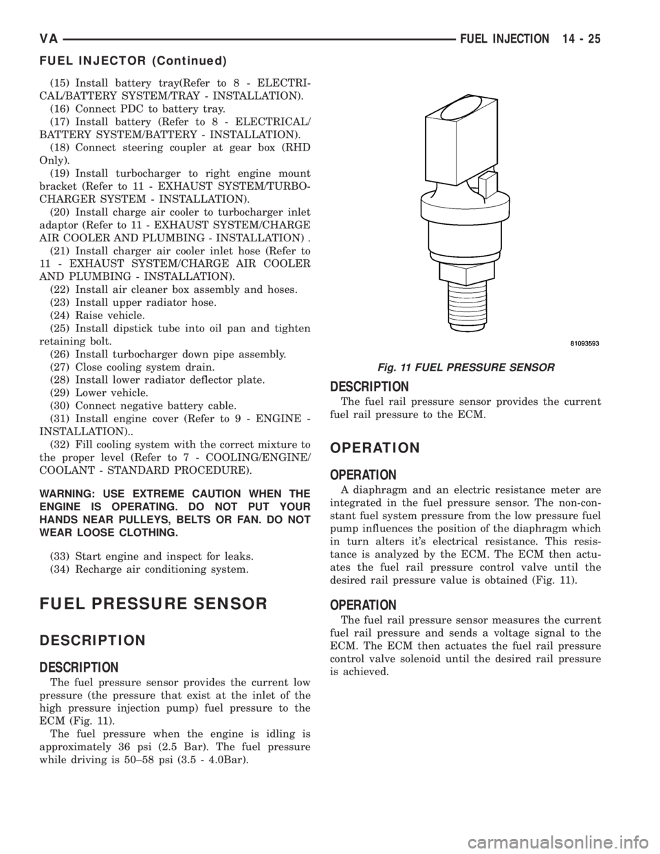
The fuel pressure sensor provides the current low
pressure (the pressure that exist at the inlet of the
high pressure injection pump) fuel pressure to the
ECM (Fig. 11).
The fuel pressure when the engine is idling is
approximately 36 psi (2.5 Bar). The fuel pressure
while driving is 50±58 psi (3.5 - 4.0Bar).
DESCRIPTION
The fuel rail pressure sensor provides the current
fuel rail pressure to the ECM.
OPERATION
OPERATION
A diaphragm and an electric resistance meter are
integrated in the fuel pressure sensor. The non-con-
stant fuel system pressure from the low pressure fuel
pump influences the position of the diaphragm which
in turn alters it's electrical resistance. This resis-
tance is analyzed by the ECM. The ECM then actu-
ates the fuel rail pressure control valve until the
desired rail pressure value is obtained (Fig. 11).
OPERATION
The fuel rail pressure sensor measures the current
fuel rail pressure and sends a voltage signal to the
ECM. The ECM then actuates the fuel rail pressure
control valve solenoid until the desired rail pressure
is achieved.
Fig. 11 FUEL PRESSURE SENSOR
VAFUEL INJECTION 14 - 25
FUEL INJECTOR (Continued)
Page 861 of 1232
STEERING
TABLE OF CONTENTS
page page
STEERING
DESCRIPTION..........................1
OPERATION............................1
DIAGNOSIS AND TESTING - POWER
STEERING SYSTEM....................2COLUMN...............................5
GEAR..................................8
LINKAGE..............................10
PUMP.................................12
STEERING
DESCRIPTION
CAUTION: Mopar ATF+4 Automatic Transmission
fluid or equivalent is to be used in the power steer-
ing system. No other power steering or automatic
transmission fluid is to be used in the system.
Damage may result to the power steering pump and
system if any other fluid is used, and do not over-
fill.
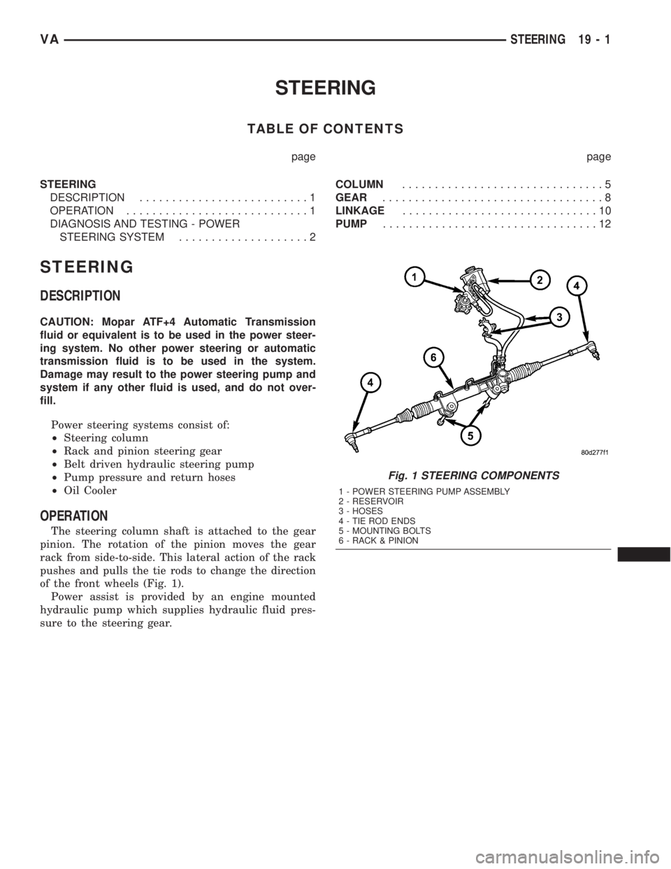
Power steering systems consist of:
²Steering column
²Rack and pinion steering gear
²Belt driven hydraulic steering pump
²Pump pressure and return hoses
²Oil Cooler
OPERATION
The steering column shaft is attached to the gear
pinion. The rotation of the pinion moves the gear
rack from side-to-side. This lateral action of the rack
pushes and pulls the tie rods to change the direction
of the front wheels (Fig. 1).
Power assist is provided by an engine mounted
hydraulic pump which supplies hydraulic fluid pres-
sure to the steering gear.
Fig. 1 STEERING COMPONENTS
1 - POWER STEERING PUMP ASSEMBLY
2 - RESERVOIR
3 - HOSES
4 - TIE ROD ENDS
5 - MOUNTING BOLTS
6 - RACK & PINION
VASTEERING 19 - 1
Page 862 of 1232
DIAGNOSIS AND TESTING - POWER STEERING SYSTEM
There is some noise in all power steering systems. One of the most common is a hissing sound evident at a
standstill parking. Or when the steering wheel is at the end of it's travel. Hiss is a high frequency noise similar
to that of a water tap being closed slowly. The noise is present in all valves that have a high velocity fluid passing
through an orifice. There is no relationship between this noise and steering performance.
STEERING NOISE
CONDITION POSSIBLE CAUSES CORRECTION
OBJECTIONAL HISS OR
WHISTLE1. Steering intermediate shaft to dash panel
seal.1. Check and repair seal at dash
panel.
2. Noisy valve in power steering gear. 2. Replace steering gear.
RATTLE OR CLUNK 1. Gear mounting bolts loose. 1. Tighten bolts to specification.
2. Loose or damaged suspension
components.2. Inspect and repair suspension.
3. Internal gear noise. 3. Replace steering gear.
4. Pressure hose in contact with other
components.4. Reposition hose.
5. Loose or damaged intermediate shaft or
column.5. Inspect and repair or replace.
CHIRP OR SQUEAL 1. Loose belt. 1. Adjust or replace.
WHINE OR GROWL 1. Low fluid level. 1. Fill to proper level.
2. Pressure hose in contact with other
components.2. Reposition hose.
3. Internal pump noise. 3. Replace pump.
4. Air in fluid 4. Check for lekas, Evacuate air
from P/S system.
SUCKING AIR SOUND 1. Loose return line clamp. 1. Replace clamp.
2. O-ring missing or damaged on hose
fitting.2. Replace o-ring.
3. Low fluid level. 3. Fill to proper level.
4. Air leak between pump and reservoir. 4. Repair as necessary.
5. Reservoir cap not installed correctly. 5. Install reservoir cap correctly.
SCRUBBING OR
KNOCKING1. Wrong tire size. 1. Verify tire size.
19 - 2 STEERINGVA
STEERING (Continued)
Page 863 of 1232
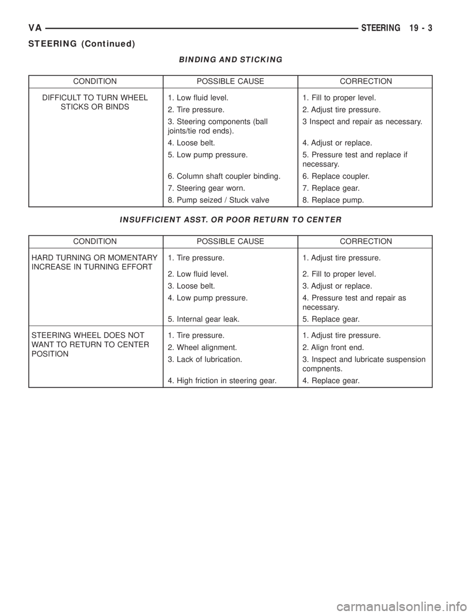
BINDING AND STICKING
CONDITION POSSIBLE CAUSE CORRECTION
DIFFICULT TO TURN WHEEL
STICKS OR BINDS1. Low fluid level. 1. Fill to proper level.
2. Tire pressure. 2. Adjust tire pressure.
3. Steering components (ball
joints/tie rod ends).3 Inspect and repair as necessary.
4. Loose belt. 4. Adjust or replace.
5. Low pump pressure. 5. Pressure test and replace if
necessary.
6. Column shaft coupler binding. 6. Replace coupler.
7. Steering gear worn. 7. Replace gear.
8. Pump seized / Stuck valve 8. Replace pump.
INSUFFICIENT ASST. OR POOR RETURN TO CENTER
CONDITION POSSIBLE CAUSE CORRECTION
HARD TURNING OR MOMENTARY
INCREASE IN TURNING EFFORT1. Tire pressure. 1. Adjust tire pressure.
2. Low fluid level. 2. Fill to proper level.
3. Loose belt. 3. Adjust or replace.
4. Low pump pressure. 4. Pressure test and repair as
necessary.
5. Internal gear leak. 5. Replace gear.
STEERING WHEEL DOES NOT
WANT TO RETURN TO CENTER
POSITION1. Tire pressure. 1. Adjust tire pressure.
2. Wheel alignment. 2. Align front end.
3. Lack of lubrication. 3. Inspect and lubricate suspension
compnents.
4. High friction in steering gear. 4. Replace gear.
VASTEERING 19 - 3
STEERING (Continued)
Page 864 of 1232
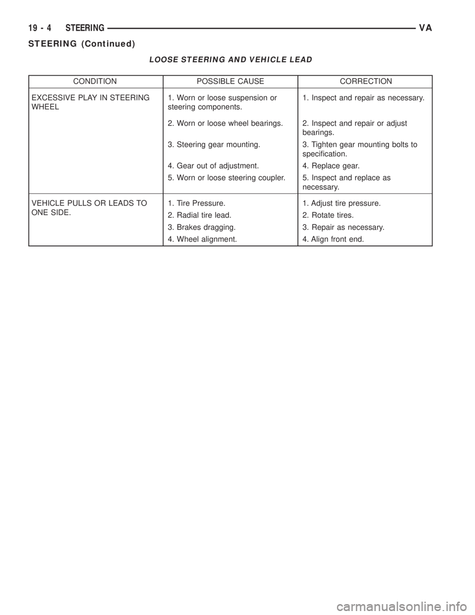
LOOSE STEERING AND VEHICLE LEAD
CONDITION POSSIBLE CAUSE CORRECTION
EXCESSIVE PLAY IN STEERING
WHEEL1. Worn or loose suspension or
steering components.1. Inspect and repair as necessary.
2. Worn or loose wheel bearings. 2. Inspect and repair or adjust
bearings.
3. Steering gear mounting. 3. Tighten gear mounting bolts to
specification.
4. Gear out of adjustment. 4. Replace gear.
5. Worn or loose steering coupler. 5. Inspect and replace as
necessary.
VEHICLE PULLS OR LEADS TO
ONE SIDE.1. Tire Pressure. 1. Adjust tire pressure.
2. Radial tire lead. 2. Rotate tires.
3. Brakes dragging. 3. Repair as necessary.
4. Wheel alignment. 4. Align front end.
19 - 4 STEERINGVA
STEERING (Continued)
Page 865 of 1232
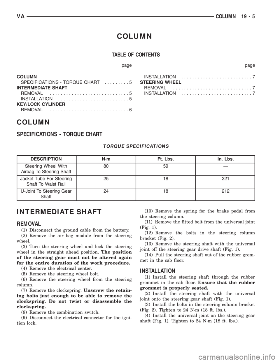
COLUMN
TABLE OF CONTENTS
page page
COLUMN
SPECIFICATIONS - TORQUE CHART.........5
INTERMEDIATE SHAFT
REMOVAL.............................5
INSTALLATION..........................5
KEY/LOCK CYLINDER
REMOVAL.............................6INSTALLATION..........................7
STEERING WHEEL
REMOVAL.............................7
INSTALLATION..........................7
COLUMN
SPECIFICATIONS - TORQUE CHART
TORQUE SPECIFICATIONS
DESCRIPTION N´m Ft. Lbs. In. Lbs.
Steering Wheel With
Airbag To Steering Shaft80 59 Ð
Jacket Tube For Steering
Shaft To Waist Rail25 18 221
U-Joint To Steering Gear
Shaft24 18 212
INTERMEDIATE SHAFT
REMOVAL
(1) Disconnect the ground cable from the battery.
(2) Remove the air bag module from the steering
wheel.
(3) Turn the steering wheel and lock the steering
wheel in the straight ahead position.The position
of the steering gear must not be altered again
for the entire duration of the work procedure.
(4) Remove the electrical center.
(5) Remove the steering wheel bolt.
(6) Remove the steering wheel from the steering
column.
(7) Remove the clockspring.Unscrew the retain-
ing bolts just enough to be able to remove the
clockspring. Do not twist or disassemble the
clockspring.
(8) Remove the combination switch.
(9) Disconnect the electrical connector for the igni-
tion lock.(10) Remove the spring for the brake pedal from
the steering column.
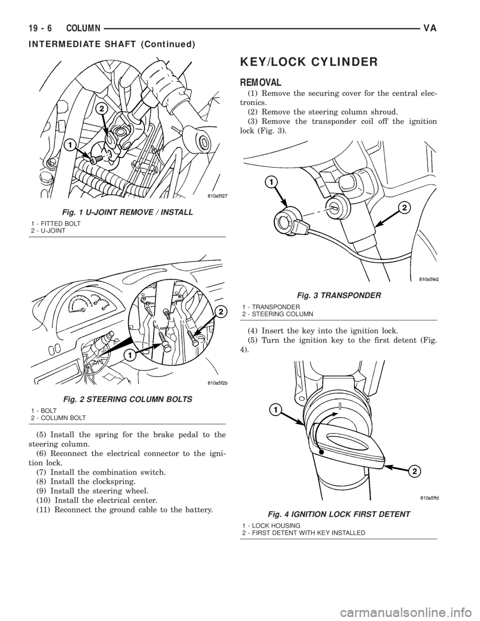
(11) Remove the fitted bolt from the universal joint
(Fig. 1).
(12) Remove the bolts in the steering column
bracket (Fig. 2).
(13) Remove the steering shaft with the universal
joint off the steering gear drive shaft (Fig. 1).
(14) Pull the steering shaft out of the rubber grom-
met in the cab floor.
INSTALLATION
(1) Install the steering shaft through the rubber
grommet in the cab floor.Ensure that the rubber
grommet is properly seated.
(2) Install the steering shaft with the universal
joint onto the steering gear shaft (Fig. 1).
(3) Install the bolts in the steering column bracket
(Fig. 2). Tighten to 24 N´m (18 ft. lbs.).
(4) Install the universal joint on the steering gear
shaft (Fig. 1). Tighten to 24 N´m (18 ft. lbs.).
VACOLUMN 19 - 5
Page 866 of 1232
(5) Install the spring for the brake pedal to the
steering column.
(6) Reconnect the electrical connector to the igni-
tion lock.
(7) Install the combination switch.
(8) Install the clockspring.
(9) Install the steering wheel.
(10) Install the electrical center.
(11) Reconnect the ground cable to the battery.
KEY/LOCK CYLINDER
REMOVAL
(1) Remove the securing cover for the central elec-
tronics.
(2) Remove the steering column shroud.
(3) Remove the transponder coil off the ignition
lock (Fig. 3).
(4) Insert the key into the ignition lock.
(5) Turn the ignition key to the first detent (Fig.
4).
Fig. 1 U-JOINT REMOVE / INSTALL
1 - FITTED BOLT
2 - U-JOINT
Fig. 2 STEERING COLUMN BOLTS
1 - BOLT
2 - COLUMN BOLT
Fig. 3 TRANSPONDER
1 - TRANSPONDER
2 - STEERING COLUMN
Fig. 4 IGNITION LOCK FIRST DETENT
1 - LOCK HOUSING
2 - FIRST DETENT WITH KEY INSTALLED
19 - 6 COLUMNVA
INTERMEDIATE SHAFT (Continued)