2005 MERCEDES-BENZ SPRINTER steering
[x] Cancel search: steeringPage 287 of 1232
and methods. Proper testing of the intermittent wipe
logic circuitry within the fuse block requires the use
of a DRBIIItscan tool. Refer to the appropriate diag-
nostic information. Refer to the owner's manual in
the vehicle glove box for more information on the fea-
tures and operation of the wiper and washer system.
DIAGNOSIS AND TESTING - WIPER &
WASHER SYSTEM
If the wiper motor operates, but the wipers do not
move on the windshield, replace the faulty wiper
linkage module. If the washer pump/motor operates,
but no washer fluid is dispensed on the glass; or, if
the wipers operate, but chatter, lift, or do not clear
the glass, clean and inspect the wiper and washer
system components as required. (Refer to 8 - ELEC-
TRICAL/WIPERS/WASHERS - CLEANING) and
(Refer to 8 - ELECTRICAL/WIPERS/WASHERS -
INSPECTION). For diagnosis and testing of the
multi-function switch (Refer to 8 - ELECTRICAL/
LAMPS/LIGHTING - EXTERIOR/MULTI-FUNC-
TION SWITCH - DIAGNOSIS AND TESTING).
Refer to the appropriate wiring information. The wir-
ing information includes wiring diagrams, proper
wire and connector repair procedures, details of wire
harness routing and retention, connector pin-out
information and location views for the various wire
harness connectors, splices and grounds.
The hard wired circuits and components of the
wiper and washer system may be diagnosed and
tested using conventional diagnostic tools and proce-
dures. However, conventional diagnostic methods
may not prove conclusive in the diagnosis of the
intermittent wipe logic circuitry contained within the
fuse block underneath the steering column. The most
reliable, efficient, and accurate means to diagnose
the intermittent wipe logic circuitry requires the use
of a DRBIIItscan tool. Refer to the appropriate diag-
nostic information.
WARNING: ON VEHICLES EQUIPPED WITH AIR-
BAGS, DISABLE THE SUPPLEMENTAL RESTRAINT
SYSTEM BEFORE ATTEMPTING ANY STEERING
WHEEL, STEERING COLUMN, DRIVER AIRBAG,
PASSENGER AIRBAG, SEAT BELT TENSIONER, OR
INSTRUMENT PANEL COMPONENT DIAGNOSIS OR
SERVICE. DISCONNECT AND ISOLATE THE BAT-
TERY NEGATIVE (GROUND) CABLE, THEN WAIT
TWO MINUTES FOR THE SYSTEM CAPACITOR TO
DISCHARGE BEFORE PERFORMING FURTHER
DIAGNOSIS OR SERVICE. THIS IS THE ONLY SURE
WAY TO DISABLE THE SUPPLEMENTAL
RESTRAINT SYSTEM. FAILURE TO TAKE THE
PROPER PRECAUTIONS COULD RESULT IN ACCI-
DENTAL AIRBAG DEPLOYMENT AND POSSIBLE
PERSONAL INJURY.
CLEANING - WIPER & WASHER SYSTEM
WIPER SYSTEM
The squeegees of wiper blades exposed to the ele-
ments for a long time tend to lose their wiping effec-
tiveness. Periodic cleaning of the squeegees is
suggested to remove any deposits of salt or road film.
The wiper blades, arms, and windshield glass should
only be cleaned using a sponge or soft cloth and
windshield washer fluid, a mild detergent, or a non-
abrasive cleaner. If the wiper blades continue to
leave streaks, smears, hazing, or beading on the
glass after thorough cleaning of the squeegees and
the glass, the entire wiper blade assembly must be
replaced.
CAUTION: Protect the rubber squeegees of the
wiper blades from any petroleum-based cleaners,
solvents, or contaminants. These products can rap-
idly deteriorate the rubber squeegees.
WASHER SYSTEM
If the washer system is contaminated with foreign
material, drain the washer reservoir by removing the
washer pump/motor from the reservoir. Clean foreign
material from the inside of the washer pump/motor
inlet nipple and the washer reservoir using clean
washer fluid, a mild detergent, or a non-abrasive
cleaner. Flush foreign material from the washer sys-
tem plumbing by first disconnecting the washer
hoses from the washer nozzles, then running the
washer pump/motor to run clean washer fluid or
water through the system. Plugged or restricted
washer nozzles should be carefully back-flushed
using compressed air. If the washer nozzle obstruc-
tion cannot be cleared, replace the washer nozzle.
CAUTION: Never introduce petroleum-based clean-
ers, solvents, or contaminants into the washer sys-
tem. These products can rapidly deteriorate the
rubber seals and hoses of the washer system, as
well as the rubber squeegees of the wiper blades.
CAUTION: Never use compressed air to flush the
washer system plumbing. Compressed air pres-
sures are too great for the washer system plumbing
components and will result in further system dam-
age. Never use sharp instruments to clear a
plugged washer nozzle or damage to the nozzle ori-
fice and improper nozzle spray patterns will result.
VAWIPERS/WASHERS 8R - 5
WIPERS/WASHERS (Continued)
Page 301 of 1232
WASHERS/FRONT WIPER MOTOR -
INSTALLATION).
(2) Carefully position the wiper linkage module
and wiper motor to the underside of the cowl top
panel as a unit (Fig. 22).
(3) Install and tighten the two screws that secure
the wiper linkage module motor bracket to the flange
on the underside of the cowl top panel. Tighten the
screws to 6 N´m (50 in. lbs.).
(4) Install and tighten the nut and washer that
secures each wiper pivot housing to the outside of the
cowl top panel.
(5) Reconnect the wiper motor pigtail wire connec-
tor to the vehicle wire harness connector.
(6) Reinstall the ventilation housing onto the dash
panel and the underside of the cowl top panel (Fig.
21).
(7) Reinstall the wiper arms onto the wiper pivots.
(Refer to 8 - ELECTRICAL/WIPERS/WASHERS/
WIPER ARM - INSTALLATION).
(8) Reconnect the battery negative cable.
WIPER MOTOR
DESCRIPTION
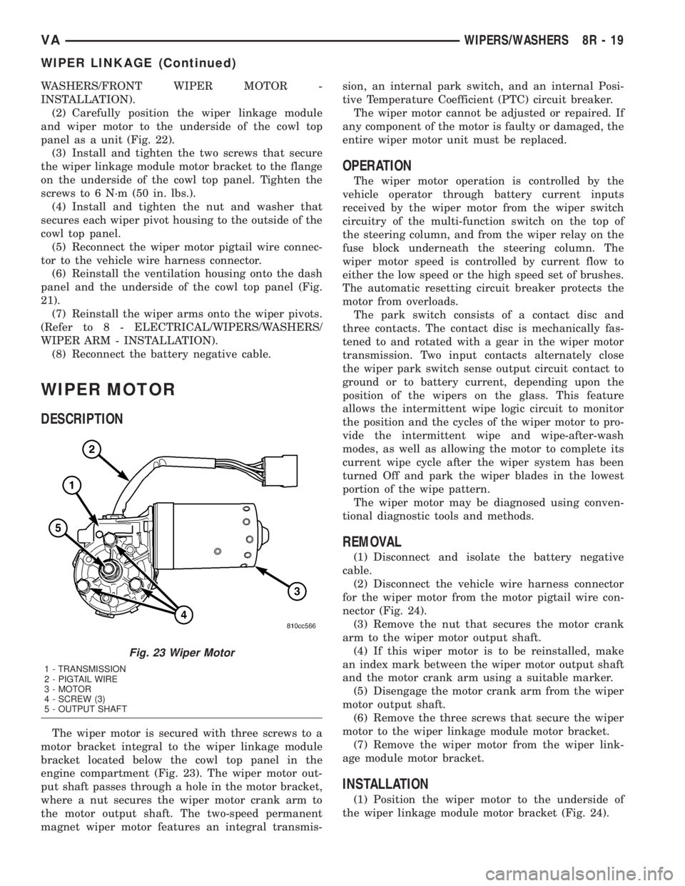
The wiper motor is secured with three screws to a
motor bracket integral to the wiper linkage module
bracket located below the cowl top panel in the
engine compartment (Fig. 23). The wiper motor out-
put shaft passes through a hole in the motor bracket,
where a nut secures the wiper motor crank arm to
the motor output shaft. The two-speed permanent
magnet wiper motor features an integral transmis-sion, an internal park switch, and an internal Posi-
tive Temperature Coefficient (PTC) circuit breaker.
The wiper motor cannot be adjusted or repaired. If
any component of the motor is faulty or damaged, the
entire wiper motor unit must be replaced.
OPERATION
The wiper motor operation is controlled by the
vehicle operator through battery current inputs
received by the wiper motor from the wiper switch
circuitry of the multi-function switch on the top of
the steering column, and from the wiper relay on the
fuse block underneath the steering column. The
wiper motor speed is controlled by current flow to
either the low speed or the high speed set of brushes.
The automatic resetting circuit breaker protects the
motor from overloads.
The park switch consists of a contact disc and
three contacts. The contact disc is mechanically fas-
tened to and rotated with a gear in the wiper motor
transmission. Two input contacts alternately close
the wiper park switch sense output circuit contact to
ground or to battery current, depending upon the
position of the wipers on the glass. This feature
allows the intermittent wipe logic circuit to monitor
the position and the cycles of the wiper motor to pro-
vide the intermittent wipe and wipe-after-wash
modes, as well as allowing the motor to complete its
current wipe cycle after the wiper system has been
turned Off and park the wiper blades in the lowest
portion of the wipe pattern.
The wiper motor may be diagnosed using conven-
tional diagnostic tools and methods.
REMOVAL
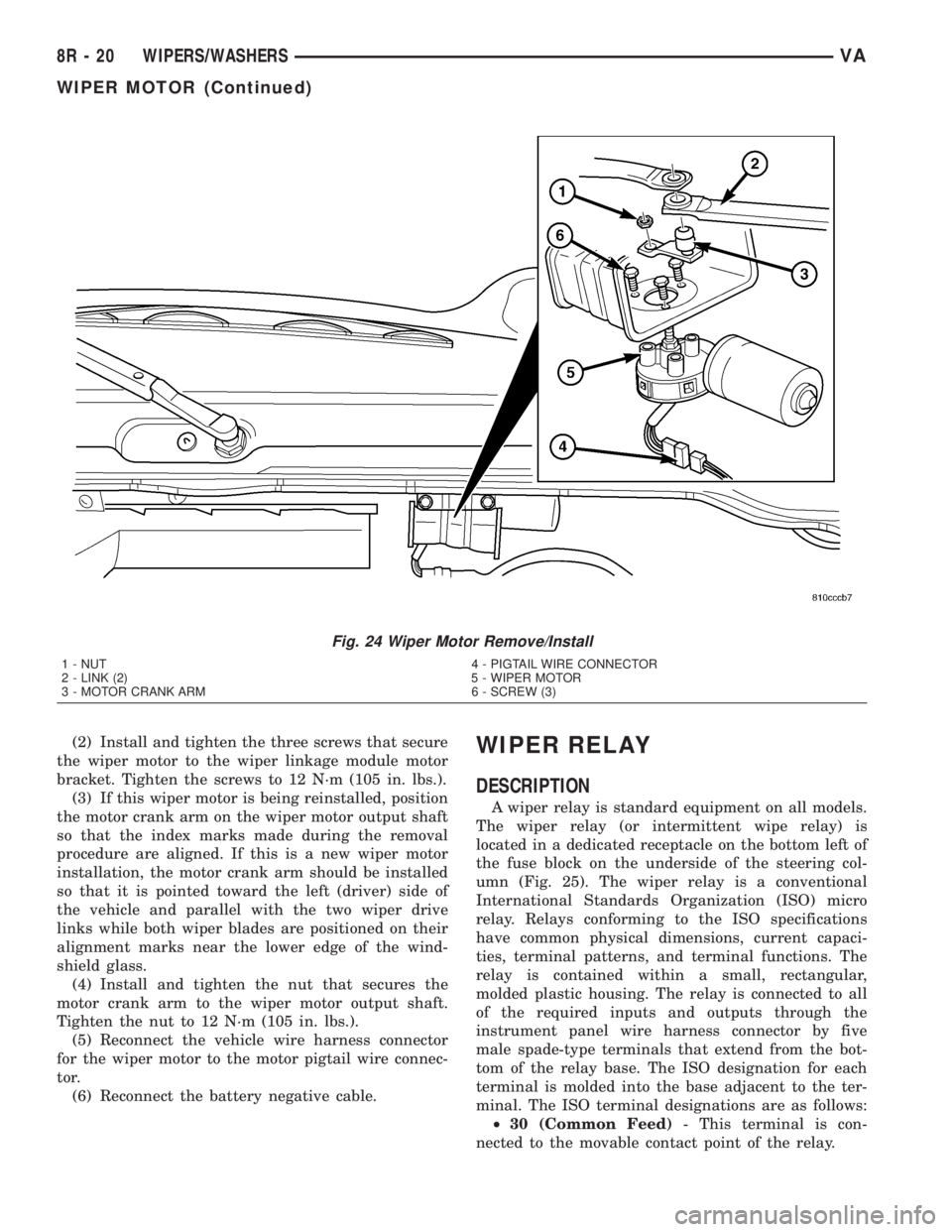
(1) Disconnect and isolate the battery negative
cable.
(2) Disconnect the vehicle wire harness connector
for the wiper motor from the motor pigtail wire con-
nector (Fig. 24).
(3) Remove the nut that secures the motor crank
arm to the wiper motor output shaft.
(4) If this wiper motor is to be reinstalled, make
an index mark between the wiper motor output shaft
and the motor crank arm using a suitable marker.
(5) Disengage the motor crank arm from the wiper
motor output shaft.
(6) Remove the three screws that secure the wiper
motor to the wiper linkage module motor bracket.
(7) Remove the wiper motor from the wiper link-
age module motor bracket.
INSTALLATION
(1) Position the wiper motor to the underside of
the wiper linkage module motor bracket (Fig. 24).
Fig. 23 Wiper Motor
1 - TRANSMISSION
2 - PIGTAIL WIRE
3 - MOTOR
4 - SCREW (3)
5 - OUTPUT SHAFT
VAWIPERS/WASHERS 8R - 19
WIPER LINKAGE (Continued)
Page 302 of 1232
(2) Install and tighten the three screws that secure
the wiper motor to the wiper linkage module motor
bracket. Tighten the screws to 12 N´m (105 in. lbs.).
(3) If this wiper motor is being reinstalled, position
the motor crank arm on the wiper motor output shaft
so that the index marks made during the removal
procedure are aligned. If this is a new wiper motor
installation, the motor crank arm should be installed
so that it is pointed toward the left (driver) side of
the vehicle and parallel with the two wiper drive
links while both wiper blades are positioned on their
alignment marks near the lower edge of the wind-
shield glass.
(4) Install and tighten the nut that secures the
motor crank arm to the wiper motor output shaft.
Tighten the nut to 12 N´m (105 in. lbs.).
(5) Reconnect the vehicle wire harness connector
for the wiper motor to the motor pigtail wire connec-
tor.
(6) Reconnect the battery negative cable.WIPER RELAY
DESCRIPTION
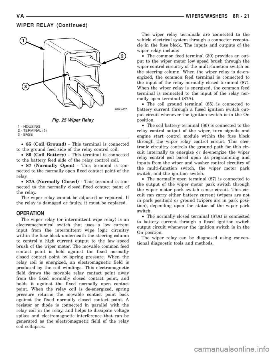
A wiper relay is standard equipment on all models.
The wiper relay (or intermittent wipe relay) is
located in a dedicated receptacle on the bottom left of
the fuse block on the underside of the steering col-
umn (Fig. 25). The wiper relay is a conventional
International Standards Organization (ISO) micro
relay. Relays conforming to the ISO specifications
have common physical dimensions, current capaci-
ties, terminal patterns, and terminal functions. The
relay is contained within a small, rectangular,
molded plastic housing. The relay is connected to all
of the required inputs and outputs through the
instrument panel wire harness connector by five
male spade-type terminals that extend from the bot-
tom of the relay base. The ISO designation for each
terminal is molded into the base adjacent to the ter-
minal. The ISO terminal designations are as follows:
²30 (Common Feed)- This terminal is con-
nected to the movable contact point of the relay.
Fig. 24 Wiper Motor Remove/Install
1 - NUT 4 - PIGTAIL WIRE CONNECTOR
2 - LINK (2) 5 - WIPER MOTOR
3 - MOTOR CRANK ARM 6 - SCREW (3)
8R - 20 WIPERS/WASHERSVA
WIPER MOTOR (Continued)
Page 303 of 1232
²85 (Coil Ground)- This terminal is connected
to the ground feed side of the relay control coil.
²86 (Coil Battery)- This terminal is connected
to the battery feed side of the relay control coil.
²87 (Normally Open)- This terminal is con-
nected to the normally open fixed contact point of the
relay.
²87A (Normally Closed)- This terminal is con-
nected to the normally closed fixed contact point of
the relay.
The wiper relay cannot be adjusted or repaired. If
the relay is damaged or faulty, it must be replaced.
OPERATION
The wiper relay (or intermittent wipe relay) is an
electromechanical switch that uses a low current
input from the intermittent wipe logic circuitry
within the fuse block underneath the steering column
to control a high current output to the low speed
brush of the wiper motor. The movable common feed
contact point is held against the fixed normally
closed contact point by spring pressure. When the
relay coil is energized, an electromagnetic field is
produced by the coil windings. This electromagnetic
field draws the movable relay contact point away
from the fixed normally closed contact point, and
holds it against the fixed normally open contact
point. When the relay coil is de-energized, spring
pressure returns the movable contact point back
against the fixed normally closed contact point. A
resistor or diode is connected in parallel with the
relay coil in the relay, and helps to dissipate voltage
spikes and electromagnetic interference that can be
generated as the electromagnetic field of the relay
coil collapses.The wiper relay terminals are connected to the
vehicle electrical system through a connector recepta-
cle in the fuse block. The inputs and outputs of the
wiper relay include:
²The common feed terminal (30) provides an out-
put to the wiper motor low speed brush through the
wiper control circuitry of the multi-function switch on
the steering column. When the wiper relay is de-en-
ergized, the common feed terminal is connected to
the input of the relay normally closed terminal (87).
When the wiper relay is energized, the common feed
terminal is connected to the input of the relay nor-
mally open terminal (87A).
²The coil ground terminal (85) is connected to
battery current through a fused ignition switch out-
put circuit whenever the ignition switch is in the On
position.
²The coil battery terminal (86) is connected to the
relay control output of the wiper, turn signals and
engine start control module within the fuse block
through the wiper relay control circuit. This elec-
tronic circuitry controls the ground path for this cir-
cuit internally to energize or de-energize the wiper
relay control coil based upon its programming and
inputs from the wiper and washer control circuitry of
the multi-function switch, the wiper motor park
switch, and the ignition switch.
²The normally open terminal (87) is connected to
the output of the wiper motor park switch through
the wiper motor park switch sense circuit. This cir-
cuit can carry either battery current (wipers are not
in park position) or ground (wipers are in park posi-
tion), depending upon the status of the wiper park
switch.
²The normally closed terminal (87A) is connected
to battery current through a fused ignition switch
output circuit whenever the ignition switch is in the
On position.
The wiper relay can be diagnosed using conven-
tional diagnostic tools and methods.
Fig. 25 Wiper Relay
1 - HOUSING
2 - TERMINAL (5)
3 - BASE
VAWIPERS/WASHERS 8R - 21
WIPER RELAY (Continued)
Page 304 of 1232
REMOVAL
WARNING: ON VEHICLES EQUIPPED WITH AIR-
BAGS, DISABLE THE SUPPLEMENTAL RESTRAINT
SYSTEM BEFORE ATTEMPTING ANY STEERING
WHEEL, STEERING COLUMN, DRIVER AIRBAG,
PASSENGER AIRBAG, SEAT BELT TENSIONER, OR
INSTRUMENT PANEL COMPONENT DIAGNOSIS OR
SERVICE. DISCONNECT AND ISOLATE THE BAT-
TERY NEGATIVE (GROUND) CABLE, THEN WAIT
TWO MINUTES FOR THE SYSTEM CAPACITOR TO
DISCHARGE BEFORE PERFORMING FURTHER
DIAGNOSIS OR SERVICE. THIS IS THE ONLY SURE
WAY TO DISABLE THE SUPPLEMENTAL
RESTRAINT SYSTEM. FAILURE TO TAKE THE
PROPER PRECAUTIONS COULD RESULT IN ACCI-
DENTAL AIRBAG DEPLOYMENT AND POSSIBLE
PERSONAL INJURY.
(1) Disconnect and isolate the battery negative
cable.
(2) Remove the fuse access panel from the steering
column opening cover below the steering column on
the instrument panel.
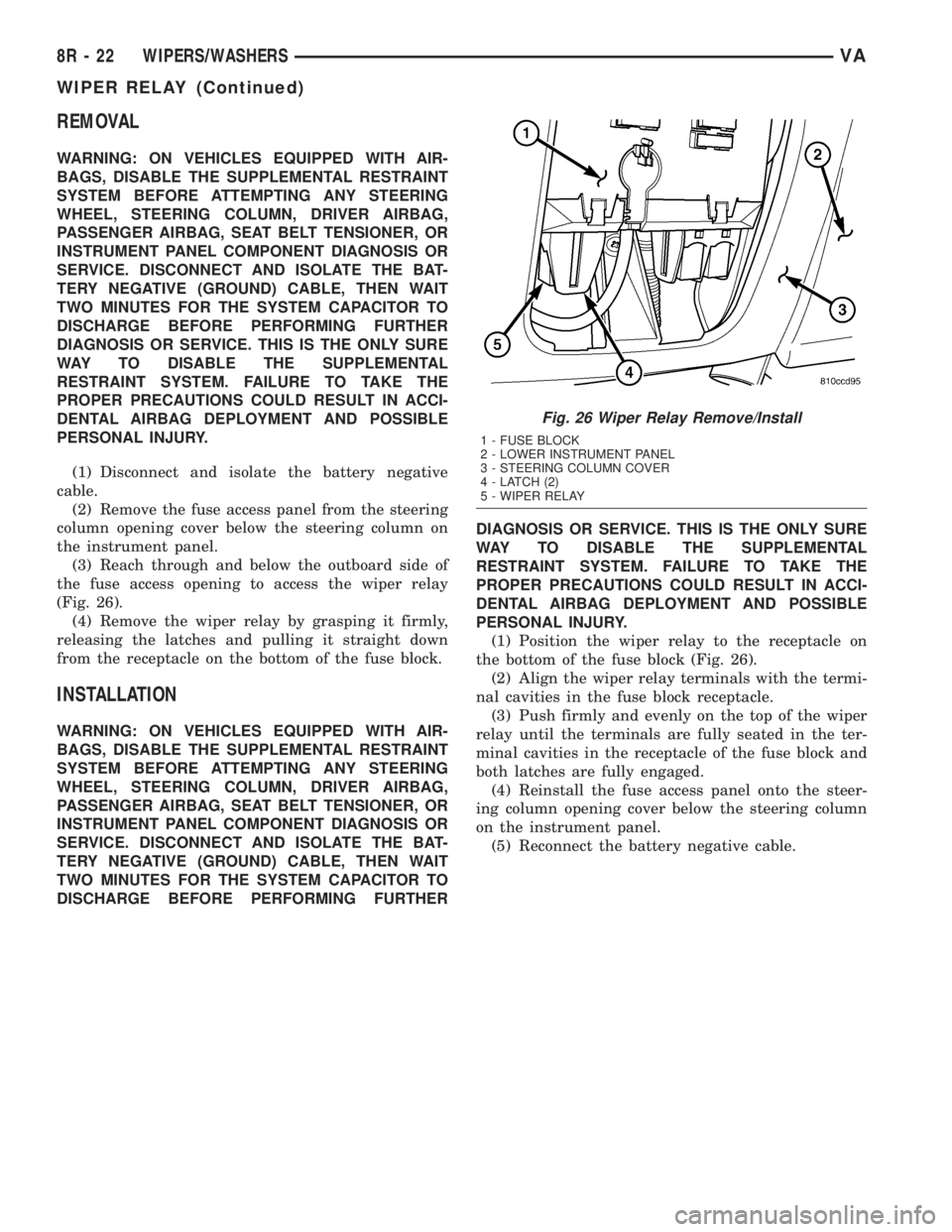
(3) Reach through and below the outboard side of
the fuse access opening to access the wiper relay
(Fig. 26).
(4) Remove the wiper relay by grasping it firmly,
releasing the latches and pulling it straight down
from the receptacle on the bottom of the fuse block.
INSTALLATION
WARNING: ON VEHICLES EQUIPPED WITH AIR-
BAGS, DISABLE THE SUPPLEMENTAL RESTRAINT
SYSTEM BEFORE ATTEMPTING ANY STEERING
WHEEL, STEERING COLUMN, DRIVER AIRBAG,
PASSENGER AIRBAG, SEAT BELT TENSIONER, OR
INSTRUMENT PANEL COMPONENT DIAGNOSIS OR
SERVICE. DISCONNECT AND ISOLATE THE BAT-
TERY NEGATIVE (GROUND) CABLE, THEN WAIT
TWO MINUTES FOR THE SYSTEM CAPACITOR TO
DISCHARGE BEFORE PERFORMING FURTHERDIAGNOSIS OR SERVICE. THIS IS THE ONLY SURE
WAY TO DISABLE THE SUPPLEMENTAL
RESTRAINT SYSTEM. FAILURE TO TAKE THE
PROPER PRECAUTIONS COULD RESULT IN ACCI-
DENTAL AIRBAG DEPLOYMENT AND POSSIBLE
PERSONAL INJURY.
(1) Position the wiper relay to the receptacle on
the bottom of the fuse block (Fig. 26).
(2) Align the wiper relay terminals with the termi-
nal cavities in the fuse block receptacle.
(3) Push firmly and evenly on the top of the wiper
relay until the terminals are fully seated in the ter-
minal cavities in the receptacle of the fuse block and
both latches are fully engaged.
(4) Reinstall the fuse access panel onto the steer-
ing column opening cover below the steering column
on the instrument panel.
(5) Reconnect the battery negative cable.
Fig. 26 Wiper Relay Remove/Install
1 - FUSE BLOCK
2 - LOWER INSTRUMENT PANEL
3 - STEERING COLUMN COVER
4 - LATCH (2)
5 - WIPER RELAY
8R - 22 WIPERS/WASHERSVA
WIPER RELAY (Continued)
Page 695 of 1232
8W-91 CONNECTOR/GROUND/SPLICE LOCATION
TABLE OF CONTENTS
page
CONNECTOR/GROUND/SPLICE LOCATION
DESCRIPTION..........................1
CONNECTOR/GROUND/SPLICE
LOCATION
DESCRIPTION
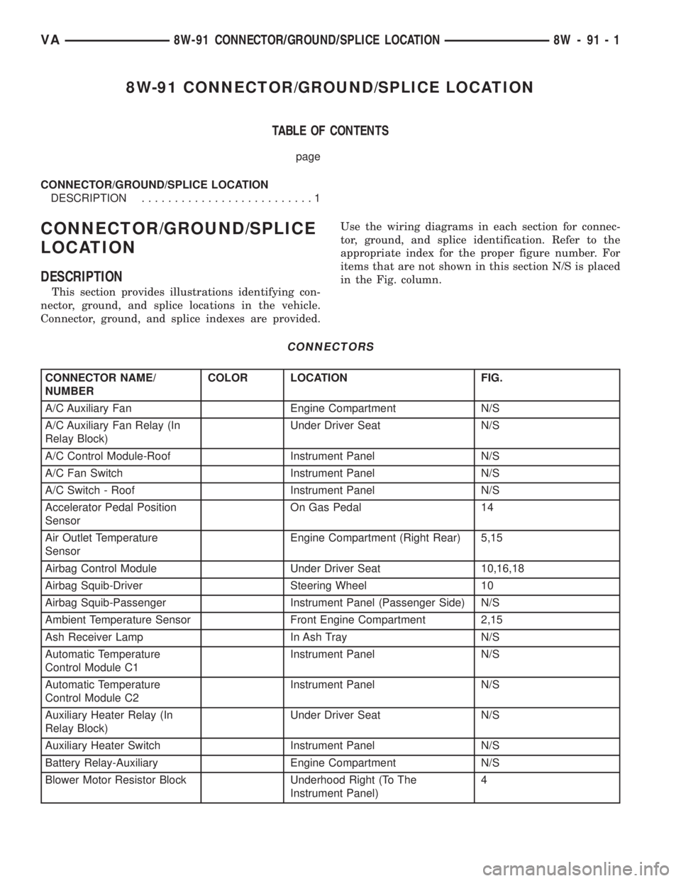
This section provides illustrations identifying con-
nector, ground, and splice locations in the vehicle.
Connector, ground, and splice indexes are provided.Use the wiring diagrams in each section for connec-
tor, ground, and splice identification. Refer to the
appropriate index for the proper figure number. For
items that are not shown in this section N/S is placed
in the Fig. column.
CONNECTORS
CONNECTOR NAME/
NUMBERCOLOR LOCATION FIG.
A/C Auxiliary Fan Engine Compartment N/S
A/C Auxiliary Fan Relay (In
Relay Block)Under Driver Seat N/S
A/C Control Module-Roof Instrument Panel N/S
A/C Fan Switch Instrument Panel N/S
A/C Switch - Roof Instrument Panel N/S
Accelerator Pedal Position
SensorOn Gas Pedal 14
Air Outlet Temperature
SensorEngine Compartment (Right Rear) 5,15
Airbag Control Module Under Driver Seat 10,16,18
Airbag Squib-Driver Steering Wheel 10
Airbag Squib-Passenger Instrument Panel (Passenger Side) N/S
Ambient Temperature Sensor Front Engine Compartment 2,15
Ash Receiver Lamp In Ash Tray N/S
Automatic Temperature
Control Module C1Instrument Panel N/S
Automatic Temperature
Control Module C2Instrument Panel N/S
Auxiliary Heater Relay (In
Relay Block)Under Driver Seat N/S
Auxiliary Heater Switch Instrument Panel N/S
Battery Relay-Auxiliary Engine Compartment N/S
Blower Motor Resistor Block Underhood Right (To The
Instrument Panel)4
VA8W-91 CONNECTOR/GROUND/SPLICE LOCATION 8W - 91 - 1
Page 697 of 1232
CONNECTOR NAME/
NUMBERCOLOR LOCATION FIG.
Cabin Heater Assembly C1 Instrument Panel N/S
Cabin Heater Assembly C2 Instrument Panel N/S
Camshaft Position Sensor Engine Compartment 7
Center High Mounted Stop
LampRear Vehicle N/S
Central Timer Module C1 Instrument Panel N/S
Central Timer Module C2 Instrument Panel N/S
Cigar Lighter Near Ash Tray N/S
Cigar Lighter Lamp Near Cigar Lighter N/S
Circulation Pump (Cabin
Heater Module)Engine Compartment-Front 4
Circulation Pump Diode Engine Compartment N/S
Circulation Pump Relay
(Relay Block)Under Driver Seat N/S
Clockspring C1 Steering Wheel 10
Clockspring C2 Steering Wheel 10,14
Contact Plate-Left Rear
License PlateRear Of Vehicle On Left N/S
Contact Switch Door-Right
RearRight Rear Door 21
Controller Antilock Brake Engine Compartment-Left 2
Courtesy Lamp - Driver Driver Door 20
Courtesy Lamp - Left Sliding
DoorLeft B-Pillar 20
Courtesy Lamp - Passenger
DoorPassenger Door 20
Courtesy Lamp - Right Rear
DoorRight Rear Door 20
Courtesy Lamp - Right
Sliding DoorRight B-Pillar 20
Crankcase Heater Engine Compartment N/S
Crankshaft Position Sensor On Engine N/S
CTEL Connector Instrument Panel N/S
Cylinder Lock Switch-Driver Driver Door 21
D(+) Relay Under Driver Seat N/S
Data Link Connector Under Dash N/S
Daytime Running Lamp
Relay (Relay Block)Under Driver Seat N/S
Daytime Running Lamp
Relay-Left Side (Relay Block)Under Driver Seat N/S
Daytime Running Lamp
Relay-Right Side (Relay
Block)Under Driver Seat N/S
Differential Lock Solenoid
ValveUnderbody 24
VA8W-91 CONNECTOR/GROUND/SPLICE LOCATION 8W - 91 - 3
CONNECTOR/GROUND/SPLICE LOCATION (Continued)
Page 699 of 1232
CONNECTOR NAME/
NUMBERCOLOR LOCATION FIG.
Fog Lamp Switch Instrument Panel N/S
Fuel Injector No. 1 Engine Compartment 7
Fuel Injector No. 2 Engine Compartment 6,7
Fuel Injector No. 3 Engine Compartment 6,7
Fuel Injector No. 4 Engine Compartment 6,7
Fuel Injector No. 5 Engine Compartment 7
Fuel Level Sensor Underbody-Middle 24
Fuel Pressure Sensor Engine Compartment 6
Fuel Pressure Solenoid Engine Compartment-Rear 5
Fuel Temperature Sensor Engine Compartment 7
Fuse Block No.1 C1 Under Fuse Block No.1 N/S
Fuse Block No.1 C2 Under Fuse Block No.1 N/S
Fuse Block No.1 C3 Under Fuse Block No.1 N/S
Fuse Block No.1 C4 Under Fuse Block No.1 N/S
Fuse Block No.1 C5 Under Fuse Block No.1 N/S
Fuse Block No.1 Control
ModuleUnder Driver Seat N/S
Fuses (Fuse Block No. 1) Steering Column 13
Fuses (Fuse Block No. 2) Under Driver Seat 17
Fuses (Fuse Block No. 3) Under Driver Seat N/S
Fuses (Fuse/Relay Block) Under Driver Seat 17,18
Fuses (PDC) Battery Area 3
Generator No.1 Engine Compartment N/S
Generator No.2 Engine Compartment-Right 2,8
Glow Plug Control Module C1 Engine Compartment-Left Front 1
Glow Plug Control Module C2 Engine Compartment-Left Front 1
Glow Plug No. 1 On Engine N/S
Glow Plug No. 2 On Engine N/S
Glow Plug No. 3 On Engine N/S
Glow Plug No. 4 On Engine N/S
Glow Plug No. 5 On Engine N/S
Headlamp Adjust Switch Instrument Panel N/S
Headlamp Assembly-Left On Front Of Vehicle (Left Side) N/S
Headlamp Assembly-Right On Front Of Vehicle (Right Side) N/S
Heat Exchanger Connector Instrument Panel N/S
Heat Exchanger Switch Engine Compartment N/S
Heated Seat Module-Driver Under Driver Seat N/S
Heated Seat Module-
PassengerUnder Passenger Seat N/S
Heated Seat Switch-Driver On Driver Seat N/S
Heated Seat Switch-
PassengerOn Passenger Seat N/S
VA8W-91 CONNECTOR/GROUND/SPLICE LOCATION 8W - 91 - 5
CONNECTOR/GROUND/SPLICE LOCATION (Continued)