2005 MERCEDES-BENZ SPRINTER steering
[x] Cancel search: steeringPage 798 of 1232
(6) Remove the oil filter to allow the oil to flow off
into the oil pan.
(7) Remove the radiator assembly (Refer to 7 -
COOLING/ENGINE/RADIATOR - REMOVAL).
(8) Remove engine cover (Refer to 9 - ENGINE -
REMOVAL).
(9) Remove front cover at cylinder head (Refer to 9
- ENGINE/CYLINDER HEAD - REMOVAL).
(10) Remove accessory drive belt.
(11) Remove the high pressure fuel pump (Refer to
14 - FUEL SYSTEM/FUEL DELIVERY/FUEL PUMP
- REMOVAL).
(12) Remove water pump (Refer to 7 - COOLING/
ENGINE/WATER PUMP - REMOVAL).
(13) Remove accessory drive belt pulley and vibra-
tion damper (Refer to 9 - ENGINE/ENGINE BLOCK/
VIBRATION DAMPER - REMOVAL).
(14) Remove the power steering pump.
NOTE: NO NOT open the air conditioning system.
(15) Unplug AC compressor electrical connector
and unbolt AC compressor. Relocate in lower engine
compartmentwith outopening the system.
(16) Remove the generator with wiring attached
and relocate somewhere in the engine compartment.
(17) Install engine support fixture.
(18) Remove the oil pan.
(19) Detach the coolant hose to oil-water heat
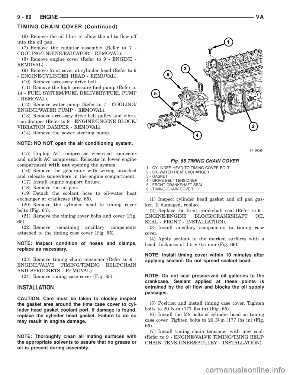
exchanger at crankcase (Fig. 65).
(20) Remove the cylinder head to timing cover
bolts (Fig. 65).
(21) Remove the timing cover bolts and cover (Fig.
65).
(22) Remove remaining ancillary components
attached to the timing case cover (Fig. 65).
NOTE: Inspect condition of hoses and clamps,
replace as necessary.
(23) Remove timing chain tensioner (Refer to 9 -
ENGINE/VALVE TIMING/TIMING BELT/CHAIN
AND SPROCKETS - REMOVAL)
(24) Remove timing case cover (Fig. 65).
INSTALLATION
CAUTION: Care must be taken to closley inspect
the gasket area around the time case cover to cyl-
inder head gasket coolant port. If damage is found,
replace the cylinder head gasket. Failure to do so
may result in engine damage.
NOTE: Thoroughly clean all mating surfaces with
the appropriate solvents to assure that no grease or
oil is present during assembly.(1) Inspect cylinder head gasket and oil pan gas-
ket. If damaged, replace.
(2) Replace the front crankshaft seal (Refer to 9 -
ENGINE/ENGINE BLOCK/CRANKSHAFT OIL
SEAL - FRONT - INSTALLATION).
(3) Install ancillary components to timing case
cover.
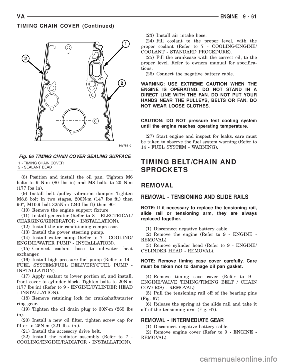
(4) Apply sealant to the marked surfaces with a
bead thickness of 1.5 0.5 mm (Fig. 66).
NOTE: Install timing cover within 10 minutes after
applying sealant. Do not spread sealant bead.
NOTE: Do not seal pressurized oil galleries to the
crankcase. Sealant applied at these points is
entrained by the oil flow and blocks the oil supply
passages.
(5) Position and install timing case cover. Tighten
bolts to 20 N´m (177 lbs in) (Fig. 65).
(6) Install the M8 bolts of cylinder head on timing
case cover. Tighten bolts to 20 N´m (177 lbs in) (Fig.
65).
(7) Install timing chain tensioner with new seal-
(Refer to 9 - ENGINE/VALVE TIMING/TMNG BELT/
CHAIN TENSIONER&PULLEY - INSTALLATION).
Fig. 65 TIMING CHAIN COVER
1 - CYLINDER HEAD TO TIMING COVER BOLT
2 - OIL-WATER HEAT EXCHANGER
3 - GASKET
4 - DRIVE BELT TENSIONER
5 - FRONT CRANKSHAFT SEAL
6 - TIMING CHAIN COVER
9 - 60 ENGINEVA
TIMING CHAIN COVER (Continued)
Page 799 of 1232
(8) Position and install the oil pan. Tighten M6
bolts to 9 N´m (80 lbs in) and M8 bolts to 20 N´m
(177 lbs in).
(9) Install belt /pulley vibration damper. Tighten
M8.8 bolt in two stages, 200N´m (147 lbs ft.) then
90É, M10.9 bolt 325N´m (240 lbs ft) then 90É.
(10) Remove the engine support fixture.
(11) Install generator (Refer to 8 - ELECTRICAL/
CHARGING/GENERATOR - INSTALLATION).
(12) Install the air conditioning compressor.
(13) Install the power steering pump.
(14) Install water pump (Refer to 7 - COOLING/
ENGINE/WATER PUMP - INSTALLATION).
(15) Connect coolant hose to oil-water heat
exchanger.
(16) Install high pressure fuel pump (Refer to 14 -
FUEL SYSTEM/FUEL DELIVERY/FUEL PUMP -
INSTALLATION).
(17) Apply sealant to lower portion of, and install,
front cover to cylinder block. Tighten bolts to 20N´m
(177 lbs in) (Refer to 9 - ENGINE/CYLINDER HEAD
- INSTALLATION).
(18) Remove retaining lock for crankshaft/starter
ring gear.
(19) Tighten the oil drain plug to 30N´m (265 lbs
in).
(20) Install a new oil filter. tighten screw cap for
filter to 25N´m (221 lbs. in.).
(21) Install the accessory drive belt.
(22) Install the radiator assembly (Refer to 7 -
COOLING/ENGINE/RADIATOR - INSTALLATION).(23) Install air intake hose.
(24) Fill coolant to the proper level, with the
proper coolant (Refer to 7 - COOLING/ENGINE/
COOLANT - STANDARD PROCEDURE).
(25) Fill the crankcase with the correct oil, to the
proper level. Refer to owners manual for specifica-
tions.
(26) Connect the negative battery cable.
WARNING: USE EXTREME CAUTION WHEN THE
ENGINE IS OPERATING. DO NOT STAND IN A
DIRECT LINE WITH THE FAN. DO NOT PUT YOUR
HANDS NEAR THE PULLEYS, BELTS OR FAN. DO
NOT WEAR LOOSE CLOTHES.
CAUTION: DO NOT pressure test cooling system
until the engine reaches operating temperature.
(27) Start engine and inspect for leaks. care must
be taken to observe the fuel system warning (Refer to
14 - FUEL SYSTEM - WARNING).
TIMING BELT/CHAIN AND
SPROCKETS
REMOVAL
REMOVAL - TENSIONING AND SLIDE RAILS
NOTE: If it necessary to replace the tensioning rail,
slide rail or tensioning arm, they are always
replaced together.
(1) Disconnect negative battery cable.
(2) Remove the engine (Refer to 9 - ENGINE -
REMOVAL).
(3) Remove cylinder head (Refer to 9 - ENGINE/
CYLINDER HEAD - REMOVAL).
NOTE: Remove timing case cover carefully. Care
must be taken not to damage oil pan gasket.
(4) Remove timing case cover (Refer to 9 -
ENGINE/VALVE TIMING/TIMING BELT / CHAIN
COVER(S) - REMOVAL).
(5) Pull the tensioning rail off of the bearing pins
(Fig. 67).
(6) Release the spring at the slide rail and take it
off of the tensioning arm (Fig. 67).
REMOVAL - INTERMEDIATE GEAR
(1) Disconnect negative battery cable.
(2) Remove engine cover (Refer to 9 - ENGINE -
REMOVAL).
Fig. 66 TIMING CHAIN COVER SEALING SURFACE
1 - TIMING CHAIN COVER
2 - SEALANT BEAD
VAENGINE 9 - 61
TIMING CHAIN COVER (Continued)
Page 815 of 1232
Low turbocharger boost pressure and low engine
performance can be caused by leaks in the charge air
cooler or it's plumbing. The following procedure out-
lines how to check for leaks in the charge air cooler
system.
(1) Loosen clamp and remove turbocharger to air
inlet duct rubber sleeve from turbocharger.
(2) Insert Special Tool 8442 Adapter into the rub-
ber sleeve. Tighten existing clamp to 8 N´m (72
in.lbs.).
CAUTION: Do not apply more than 138 kpa (20 psi)
air pressure to the charge air cooler system, sever
damage to the charge air cooler system may occur.
(3) Connect regulated air supply to air fitting on
Special Tool 8442 Adapter. Set air pressure to a Max-
imum of 138 kpa (20 psi).
(4) Using soapy water check the air inlet ducts,
rubber sleeves, charge air cooler and intake manifold
for leaks.
REMOVAL
(1) Remove front bumper.
(2) Remove headlamp assemblies.
(3) Remove front cross member together with front
grille.
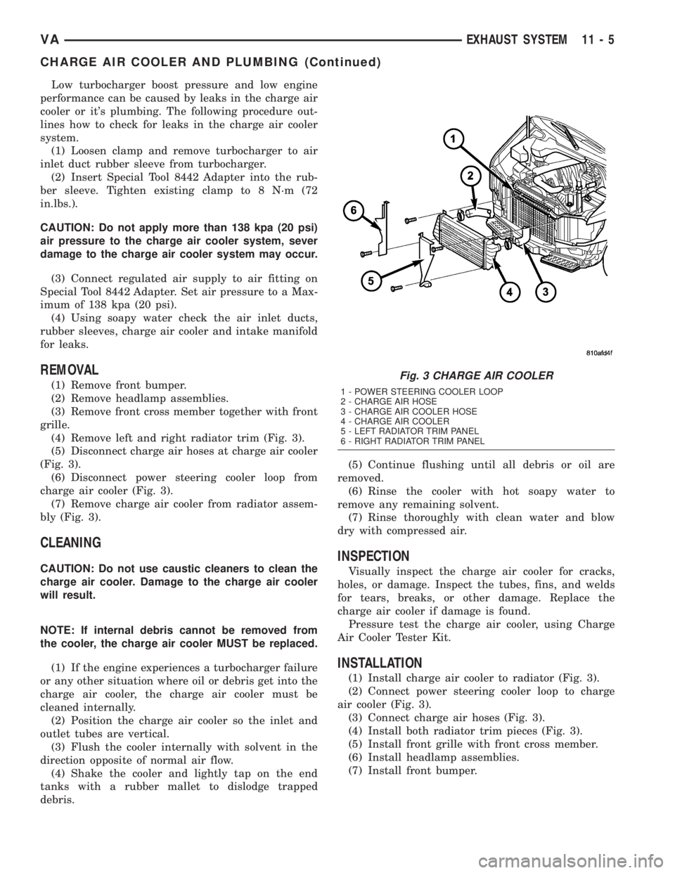
(4) Remove left and right radiator trim (Fig. 3).
(5) Disconnect charge air hoses at charge air cooler
(Fig. 3).
(6) Disconnect power steering cooler loop from
charge air cooler (Fig. 3).
(7) Remove charge air cooler from radiator assem-
bly (Fig. 3).
CLEANING
CAUTION: Do not use caustic cleaners to clean the
charge air cooler. Damage to the charge air cooler
will result.
NOTE: If internal debris cannot be removed from
the cooler, the charge air cooler MUST be replaced.
(1) If the engine experiences a turbocharger failure
or any other situation where oil or debris get into the
charge air cooler, the charge air cooler must be
cleaned internally.
(2) Position the charge air cooler so the inlet and
outlet tubes are vertical.
(3) Flush the cooler internally with solvent in the
direction opposite of normal air flow.
(4) Shake the cooler and lightly tap on the end
tanks with a rubber mallet to dislodge trapped
debris.(5) Continue flushing until all debris or oil are
removed.
(6) Rinse the cooler with hot soapy water to
remove any remaining solvent.
(7) Rinse thoroughly with clean water and blow
dry with compressed air.
INSPECTION
Visually inspect the charge air cooler for cracks,
holes, or damage. Inspect the tubes, fins, and welds
for tears, breaks, or other damage. Replace the
charge air cooler if damage is found.
Pressure test the charge air cooler, using Charge
Air Cooler Tester Kit.
INSTALLATION
(1) Install charge air cooler to radiator (Fig. 3).
(2) Connect power steering cooler loop to charge
air cooler (Fig. 3).
(3) Connect charge air hoses (Fig. 3).
(4) Install both radiator trim pieces (Fig. 3).
(5) Install front grille with front cross member.
(6) Install headlamp assemblies.
(7) Install front bumper.
Fig. 3 CHARGE AIR COOLER
1 - POWER STEERING COOLER LOOP
2 - CHARGE AIR HOSE
3 - CHARGE AIR COOLER HOSE
4 - CHARGE AIR COOLER
5 - LEFT RADIATOR TRIM PANEL
6 - RIGHT RADIATOR TRIM PANEL
VAEXHAUST SYSTEM 11 - 5
CHARGE AIR COOLER AND PLUMBING (Continued)
Page 824 of 1232
SPECIFICATIONS - TORQUE
TORQUE SPECIFICATIONS
DESCRIPTION N´m Ft. Lbs. In. Lbs.
Brake line nuts 14 10 Ð
Brake pads wear
indicator caliper bolt10 7 89
Engine cradle bolts 125 92 Ð
Engine mount bolt
to engine bracket83 61 Ð
Engine mount nuts
to engine cradle45 33 Ð
Power steering line
nuts37 27 Ð
Steering gear
mounting bolts - 1st
stage25 18 Ð
Steering Gear
mounting bolts -
2nd stage45 33 Ð
Steering Gear
mounting bolts - 3rd
stage90ÉÐÐ
Steering gear
u-joint bolt24 18 Ð
Sway bar bushing
bolts30 22 Ð
Trailer hitch angle
bracket bolts/nuts50*
See
Warning37*
See
WarningÐ
Trailer hitch frame
bolts11 0 8 1 Ð
Transmission
crossmember nuts45 33 Ð
Transmission mount
bolts/nuts45 33 Ð
WARNING: Microencapsulated bolts and self-lock-
ing nuts may only be used once. If you use
microencapsulated bolt or self-locking nuts more
than once, the self-locking function is rendered
useless. The trailer hitch may become detached
from the vehicle, possibly resulting in a serious risk
of injury and/or damage to property, including dam-
age to the vehicle.
ENGINE CRADLE
CROSSMEMBER
REMOVAL
(1) Install engine support tool 8534 or equivalent.
(2) Raise and support the vehicle. (Refer to
LUBRICATION & MAINTENANCE/HOISTING -
STANDARD PROCEDURE)
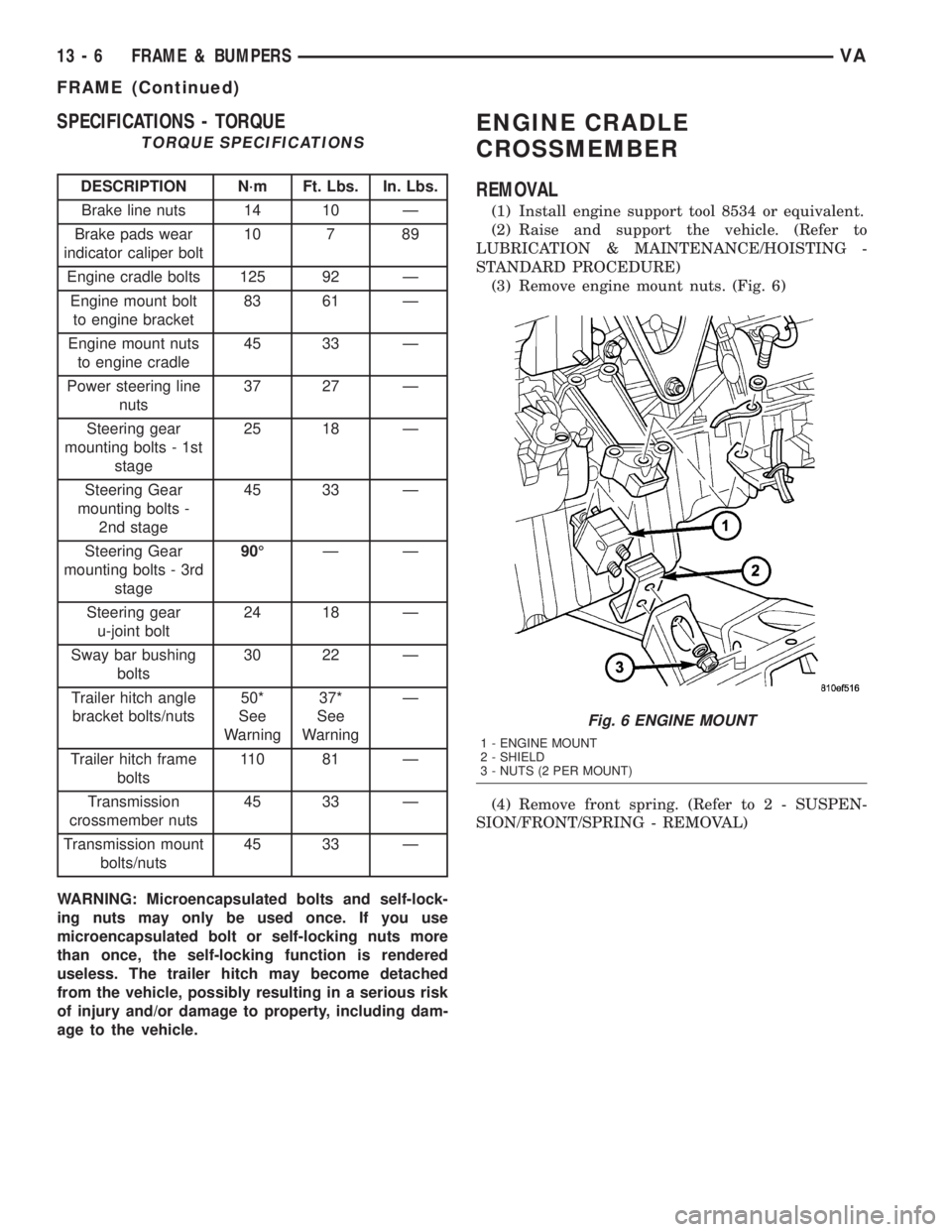
(3) Remove engine mount nuts. (Fig. 6)
(4) Remove front spring. (Refer to 2 - SUSPEN-
SION/FRONT/SPRING - REMOVAL)
Fig. 6 ENGINE MOUNT
1 - ENGINE MOUNT
2 - SHIELD
3 - NUTS (2 PER MOUNT)
13 - 6 FRAME & BUMPERSVA
FRAME (Continued)
Page 825 of 1232
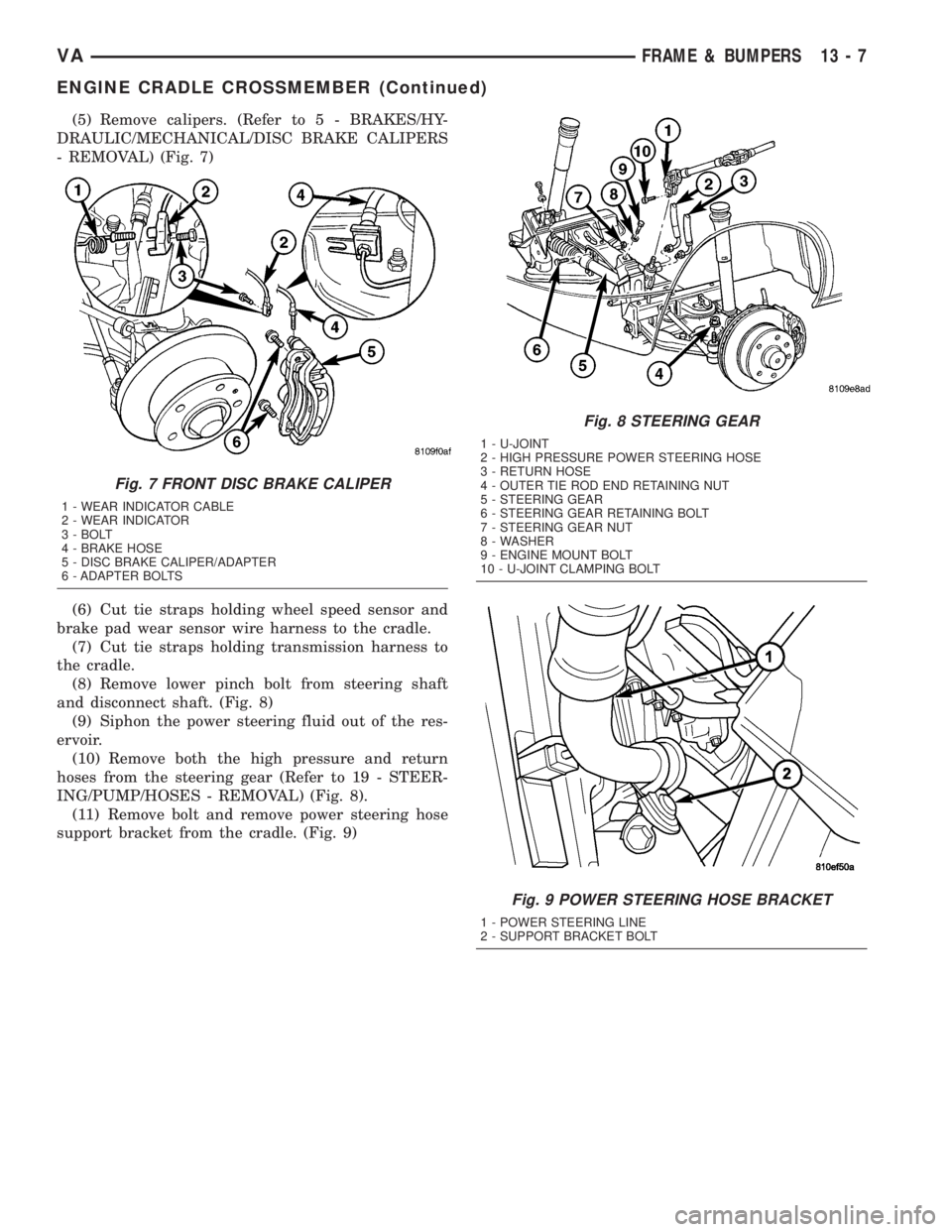
(5) Remove calipers. (Refer to 5 - BRAKES/HY-
DRAULIC/MECHANICAL/DISC BRAKE CALIPERS
- REMOVAL) (Fig. 7)
(6) Cut tie straps holding wheel speed sensor and
brake pad wear sensor wire harness to the cradle.
(7) Cut tie straps holding transmission harness to
the cradle.
(8) Remove lower pinch bolt from steering shaft
and disconnect shaft. (Fig. 8)
(9) Siphon the power steering fluid out of the res-
ervoir.
(10) Remove both the high pressure and return
hoses from the steering gear (Refer to 19 - STEER-
ING/PUMP/HOSES - REMOVAL) (Fig. 8).
(11) Remove bolt and remove power steering hose
support bracket from the cradle. (Fig. 9)
Fig. 7 FRONT DISC BRAKE CALIPER
1 - WEAR INDICATOR CABLE
2 - WEAR INDICATOR
3 - BOLT
4 - BRAKE HOSE
5 - DISC BRAKE CALIPER/ADAPTER
6 - ADAPTER BOLTS
Fig. 8 STEERING GEAR
1 - U-JOINT
2 - HIGH PRESSURE POWER STEERING HOSE
3 - RETURN HOSE
4 - OUTER TIE ROD END RETAINING NUT
5 - STEERING GEAR
6 - STEERING GEAR RETAINING BOLT
7 - STEERING GEAR NUT
8 - WASHER
9 - ENGINE MOUNT BOLT
10 - U-JOINT CLAMPING BOLT
Fig. 9 POWER STEERING HOSE BRACKET
1 - POWER STEERING LINE
2 - SUPPORT BRACKET BOLT
VAFRAME & BUMPERS 13 - 7
ENGINE CRADLE CROSSMEMBER (Continued)
Page 826 of 1232
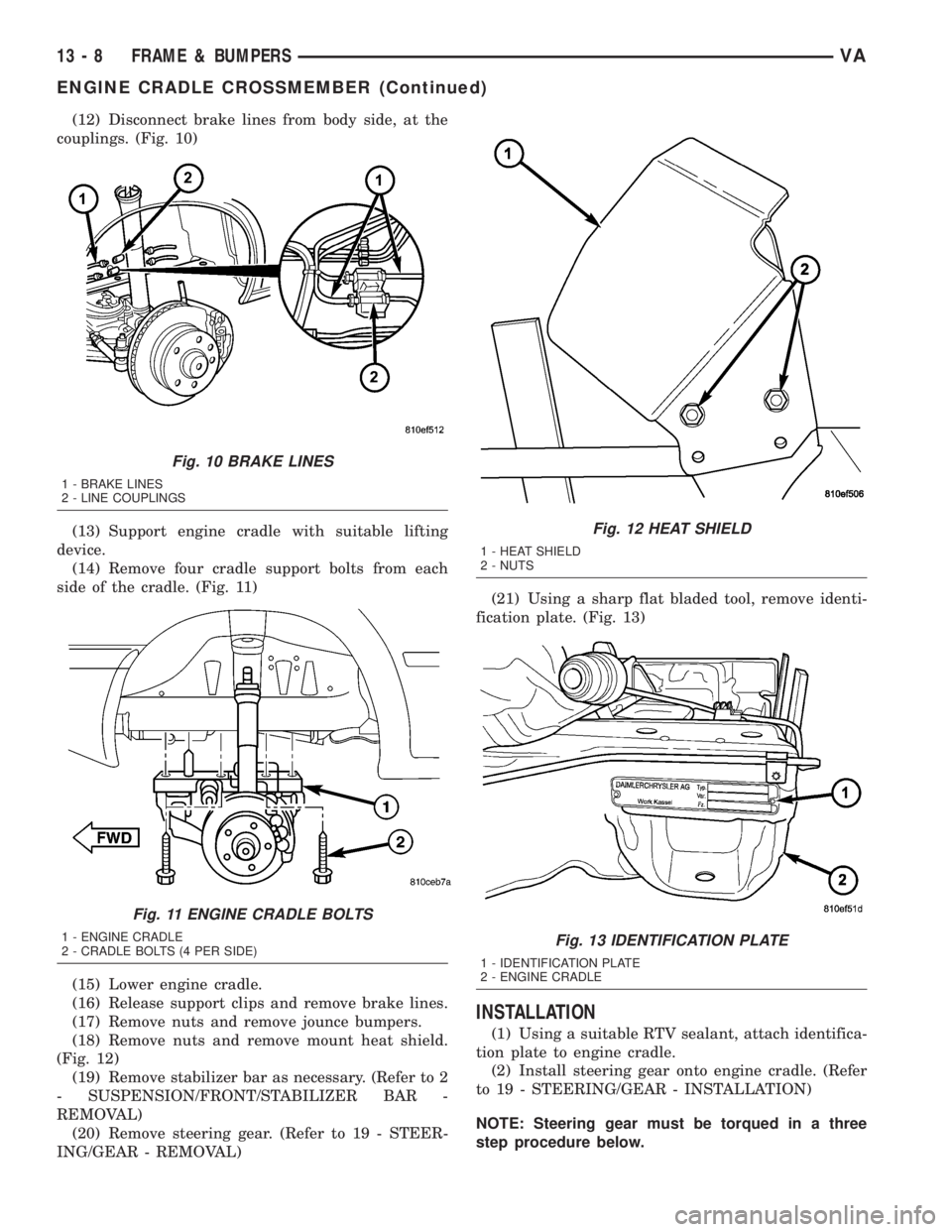
(12) Disconnect brake lines from body side, at the
couplings. (Fig. 10)
(13) Support engine cradle with suitable lifting
device.
(14) Remove four cradle support bolts from each
side of the cradle. (Fig. 11)
(15) Lower engine cradle.
(16) Release support clips and remove brake lines.
(17) Remove nuts and remove jounce bumpers.
(18) Remove nuts and remove mount heat shield.
(Fig. 12)
(19) Remove stabilizer bar as necessary. (Refer to 2
- SUSPENSION/FRONT/STABILIZER BAR -
REMOVAL)
(20) Remove steering gear. (Refer to 19 - STEER-
ING/GEAR - REMOVAL)(21) Using a sharp flat bladed tool, remove identi-
fication plate. (Fig. 13)
INSTALLATION
(1) Using a suitable RTV sealant, attach identifica-
tion plate to engine cradle.
(2) Install steering gear onto engine cradle. (Refer
to 19 - STEERING/GEAR - INSTALLATION)
NOTE: Steering gear must be torqued in a three
step procedure below.
Fig. 10 BRAKE LINES
1 - BRAKE LINES
2 - LINE COUPLINGS
Fig. 11 ENGINE CRADLE BOLTS
1 - ENGINE CRADLE
2 - CRADLE BOLTS (4 PER SIDE)
Fig. 12 HEAT SHIELD
1 - HEAT SHIELD
2 - NUTS
Fig. 13 IDENTIFICATION PLATE
1 - IDENTIFICATION PLATE
2 - ENGINE CRADLE
13 - 8 FRAME & BUMPERSVA
ENGINE CRADLE CROSSMEMBER (Continued)
Page 827 of 1232
(3) Tighten steering gear bolts in three stages as
follows.
1. Tighten to 25 N´m (18 ft. lbs.)
2. Then tighten to 45 N´m (33 ft. lbs.)
3. Then tighten bolts an additional 90É.
(4) Install stabilizer bar. (Refer to 2 - SUSPEN-
SION/FRONT/STABILIZER BAR - INSTALLATION)
(5) Install heat shield and nuts.
(6) Install jounce bumpers and install nuts.
(7) Install support clips and brake lines.
(8) Raise engine cradle into place and install bolts.
(9) Tighten bolts to 125 N´m (92 ft. lbs.).
(10) Connect brake lines at couplings and tighten
to 14 N´m (10 ft. lbs.).
(11) Position power steering hose and install sup-
port bracket bolt.
(12) Install both power steering hoses at steering
gear. (Refer to 19 - STEERING/PUMP/HOSES -
INSTALLATION)
(13) Connect steering shaft to gear and install the
lower pinch bolt.
(14) Tighten lower pinch bolt to 24 N´m (18 ft.
lbs.).
(15) Install new tie straps holding transmission
harness to cradle.
(16) Install front spring. (Refer to 2 - SUSPEN-
SION/FRONT/SPRING - INSTALLATION)
(17) Install engine mount nuts and tighten to 45
N´m (33 ft. lbs.).
(18) Install calipers. (Refer to 5 - BRAKES/HY-
DRAULIC/MECHANICAL/DISC BRAKE CALIPERS
- INSTALLATION)
(19) Install new tie straps holding wheel speed
sensors and brake pad wear sensors wire harness to
cradle.
(20) Check and align vehicle to specifications.
(Refer to 2 - SUSPENSION/WHEEL ALIGNMENT -
STANDARD PROCEDURE)
REAR CROSSMEMBER -
TRANSMISSION
REMOVAL
(1) Raise and support the vehicle. (Refer to
LUBRICATION & MAINTENANCE/HOISTING -
STANDARD PROCEDURE)
(2) Support transmission with a suitable lifting
device.
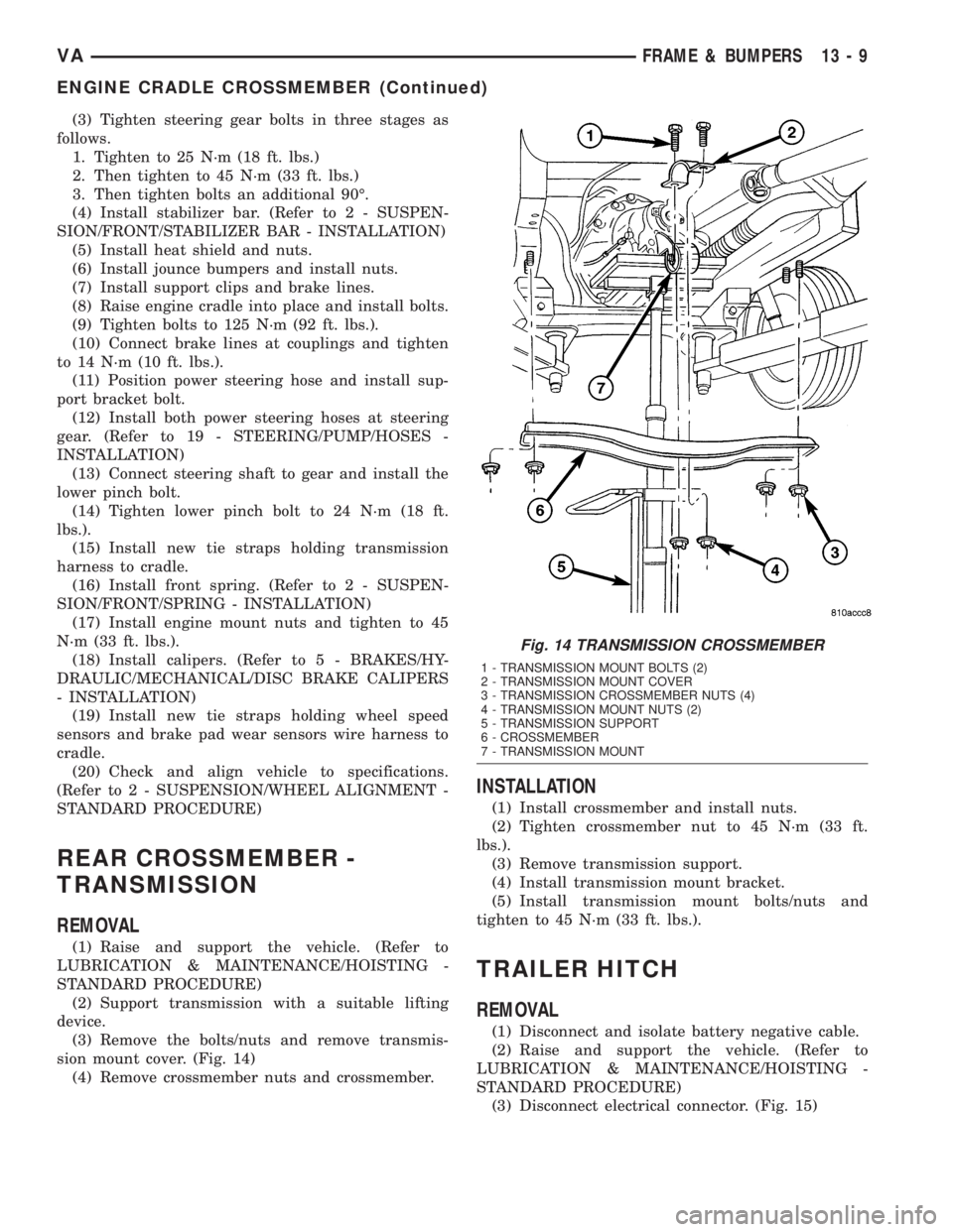
(3) Remove the bolts/nuts and remove transmis-
sion mount cover. (Fig. 14)
(4) Remove crossmember nuts and crossmember.
INSTALLATION
(1) Install crossmember and install nuts.
(2) Tighten crossmember nut to 45 N´m (33 ft.
lbs.).
(3) Remove transmission support.
(4) Install transmission mount bracket.
(5) Install transmission mount bolts/nuts and
tighten to 45 N´m (33 ft. lbs.).
TRAILER HITCH
REMOVAL
(1) Disconnect and isolate battery negative cable.
(2) Raise and support the vehicle. (Refer to
LUBRICATION & MAINTENANCE/HOISTING -
STANDARD PROCEDURE)
(3) Disconnect electrical connector. (Fig. 15)
Fig. 14 TRANSMISSION CROSSMEMBER
1 - TRANSMISSION MOUNT BOLTS (2)
2 - TRANSMISSION MOUNT COVER
3 - TRANSMISSION CROSSMEMBER NUTS (4)
4 - TRANSMISSION MOUNT NUTS (2)
5 - TRANSMISSION SUPPORT
6 - CROSSMEMBER
7 - TRANSMISSION MOUNT
VAFRAME & BUMPERS 13 - 9
ENGINE CRADLE CROSSMEMBER (Continued)
Page 851 of 1232
NOTE: Always replace the seals that seal off the
injectors at the cylinder head to the combustion
chamber and replace the retaining screws.
REMOVAL
WARNING: HIGH-PRESSURE FUEL LINES DELIVER
DIESEL FUEL UNDER EXTREME PRESSURE FROM
THE INJECTION PUMP TO THE FUEL INJECTORS.
THIS MAY BE AS HIGH AS 1600BAR (23,200 PSI).
USE EXTREME CAUTION WHEN INSPECTING FOR
HIGH-PRESSURE FUEL LEAKS. FUEL UNDER THIS
AMOUNT OF PRESSURE CAN PENETRATE SKIN
CAUSING PERSONAL INJURY OR DEATH. INSPECT
FOR HIGH-PRESSURE LEAKS WITH A SHEET OF
CARD BOARD. WEAR SAFETY GOGGLES AND
ADEQUATE PROTECTIVE CLOTHING WHEN SER-
VICING FUEL SYSTEM.
WARNING: NO SPARKS, OPEN FLAMES OR SMOK-
ING. RISK OF POISONING FROM INHALING AND
SWALLOWING FUEL. RISK OF INJURY TO EYES
AND SKIN FROM CONTACT WITH FUEL. POUR
FUELS ONLY INTO SUITABLE AND APPROPRI-
ATELY MARKED CONTAINERS. WEAR PROTECTIVE
CLOTHING.
NOTE: The engine must be lowered in the vehicle to
remove the fourth and fifth cylinders fuel injectors.
(1) Disconnect negative battery cable.
(2) Remove engine cover (Refer to 9 - ENGINE -
REMOVAL).
(3) Raise and suitably support the vehicle.
(4) Remove lower radiator deflector plate.
(5) Drain cooling system (Refer to 7 - COOLING/
ENGINE/COOLANT - STANDARD PROCEDURE).
(6) Remove turbocharger down pipe assembly.
(7) Remove oil dipstick tube retaining bolt and pull
tube from oil pan.
(8) Lower vehicle.
(9) Remove upper radiator hose.
(10) Remove air cleaner box assembly and hoses.
(11) Remove charge air cooler inlet hose.
(12) Remove charge air cooler to turbocharger inlet
adaptor.
(13) Remove turbocharger to right engine mount
bracket.
(14) Disconnect steering coupler at gear box (RHD
Only).
(15) Remove battery (Refer to 8 - ELECTRICAL/
BATTERY SYSTEM/BATTERY - REMOVAL).
(16) Unclip PDC from battery tray and set aside.(17) Remove battery tray (Refer to 8 - ELECTRI-
CAL/BATTERY SYSTEM/TRAY - REMOVAL).
(18) Remove power steering reservoir (Refer to 19 -
STEERING/PUMP/RESERVOIR - REMOVAL).
(19) Remove charger air cooler outlet hose.
(20) Remove intake manifold to left engine mount
bracket.
(21) Evacuate air conditioning system (Refer to 24
- HEATING & AIR CONDITIONING/PLUMBING -
STANDARD PROCEDURE).
(22) Disconnect air conditioning suction / discharge
lines at A/C compressor.
(23) Disconnect pedal position sensor electrical
connector.
(24) Unplug injector electrical connectors.
(25) Remove fuel / water separator to intake man-
ifold retaining bolts.
(26) Support engine with hoist.
(27) Remove engine mount through bolts.
(28) Remove right engine mount sill plate.
NOTE: Counterhold injection lines with wrench
socket at threaded connections of injectors.
(29) Disconnect fuel injector high pressure line.
(30) Remove fuel injector retaining bolt and ten-
sion claw.
(31) Suitably lower engine to gain fuel injector
access and remove injector.
NOTE: If injectors are tight, remove with extraction
claw in place of tensioning claw. If extraction claw
contacts cylinder head cover, remove cylinder head
cover. If necessary, remove injectors with threaded
adaptor and discard injector.
(32) Remove injectors (Fig. 10).
(33) Clean injectors and recesses (Refer to 14 -
FUEL SYSTEM/FUEL INJECTION/FUEL INJEC-
TOR - STANDARD PROCEDURE).
INSTALLATION
WARNING: HIGH-PRESSURE FUEL LINES DELIVER
DIESEL FUEL UNDER EXTREME PRESSURE FROM
THE INJECTION PUMP TO THE FUEL INJECTORS.
THIS MAY BE AS HIGH AS 1600BAR (23,200 PSI).
USE EXTREME CAUTION WHEN INSPECTING FOR
HIGH-PRESSURE FUEL LEAKS. FUEL UNDER THIS
AMOUNT OF PRESSURE CAN PENETRATE SKIN
CAUSING PERSONAL INJURY OR DEATH. INSPECT
FOR HIGH-PRESSURE LEAKS WITH A SHEET OF
CARD BOARD. WEAR SAFETY GOGGLES AND
ADEQUATE PROTECTIVE CLOTHING WHEN SER-
VICING FUEL SYSTEM.
VAFUEL INJECTION 14 - 23
FUEL INJECTOR (Continued)