2005 MERCEDES-BENZ SPRINTER steering
[x] Cancel search: steeringPage 875 of 1232
(5) Install the fan bracket bolts to the radiator
(Fig. 2).
(6) Install the core support bolts and reconnect the
hood latch cable.
(7) Install the right headlight assembly.
(8) Install the bolt for the turbo shield at the core
support.
(9) Install the radiator clips.
(10) Install the return lines to the cooler tube.
(11) Install the left headlight assembly.
(12) Install the grille assembly (Refer to 23 -
BODY/EXTERIOR/GRILLE - INSTALLATION).
(13) Fill the power steering fluid (Refer to 19 -
STEERING/PUMP/FLUID - STANDARD PROCE-
DURE).
HOSES
REMOVAL
REMOVAL - PRESSURE HOSE
(1) Siphon as much power steering fluid as possi-
ble out of the reservoir.
(2) Disconnect the pressure hose at the pump.
(3) Disconnect the pressure hose at the steering
gear.
(4) Remove the pressure hose mounting bracket
from the gear.
(5) Remove the pressure hose from the vehicle.
REMOVAL - RETURN LINE FROM PUMP TO
COOLER TUBE
(1) Siphon as much power steering fluid as possi-
ble out of the reservoir.
(2) Disconnect the return line at the pump.
(3) Remove the grille (Refer to 23 - BODY/EXTE-
RIOR/GRILLE - REMOVAL).
(4) Remove the left headlight assembly.
(5) Disconnect the return line at the cooler tube.
(6) Remove the return line from the vehicle.
REMOVAL - RETURN HOSE FROM GEAR TO
COOLER TUBE
(1) Siphon as much power steering fluid as possi-
ble out of the reservoir.
(2) Disconnect the return hose from the gear.(3) Remove the grille (Refer to 23 - BODY/EXTE-
RIOR/GRILLE - REMOVAL).
(4) Remove the left headlight assembly.
(5) Disconnect the return line at the cooler tube.
(6) Remove the return line from the vehicle.
INSTALLATION
INSTALLATION - PRESSURE HOSE
(1) Install the pressure hose to the vehicle.
(2) Reconnect the pressure hose at the steering
gear. Tighten to 37 N´m (27 ft.lbs.).
(3) Install the pressure hose mounting bracket to
the steering gear.
(4) Reconnect the pressure hose at the power
steering pump. Tighten to 38 N´m (28 ft.lbs.).
(5) Fill the power steering fluid (Refer to 19 -
STEERING/PUMP/FLUID - STANDARD PROCE-
DURE).
INSTALLATION - RETURN LINE FROM PUMP
TO COOLER TUBE
(1) Install the return line to the vehicle.
(2) Reconnect the return line at the cooler tube.
(3) Install the left headlight assembly.
(4) Install the grille assembly (Refer to 23 - BODY/
EXTERIOR/GRILLE - INSTALLATION).
(5) Reconnect the return line at the power steering
pump.
(6) Fill the power steering fluid (Refer to 19 -
STEERING/PUMP/FLUID - STANDARD PROCE-
DURE).
INSTALLATION - RETURN HOSE FROM GEAR
TO COOLER TUBE
(1) Install the return line to the vehicle.
(2) Reconnect the return line at the cooler tube.
(3) Install the left headlight assembly.
(4) Install the grille assembly (Refer to 23 - BODY/
EXTERIOR/GRILLE - INSTALLATION).
(5) Reconnect the return line at the power steering
gear.
(6) Fill the power steering fluid (Refer to 19 -
STEERING/PUMP/FLUID - STANDARD
PROCEDURE).
VAPUMP 19 - 15
FLUID COOLER TUBE (Continued)
Page 904 of 1232
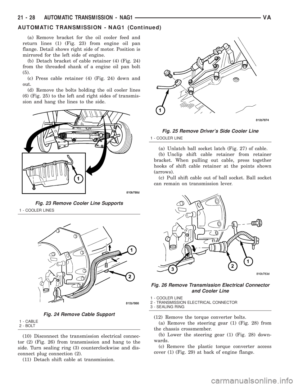
(a) Remove bracket for the oil cooler feed and
return lines (1) (Fig. 23) from engine oil pan
flange. Detail shows right side of motor. Position is
mirrored for the left side of engine.
(b) Detach bracket of cable retainer (4) (Fig. 24)
from the threaded shank of a engine oil pan bolt
(5).
(c) Press cable retainer (4) (Fig. 24) down and
out.
(d) Remove the bolts holding the oil cooler lines
(6) (Fig. 25) to the left and right sides of transmis-
sion and hang the lines to the side.
(10) Disconnect the transmission electrical connec-
tor (2) (Fig. 26) from transmission and hang to the
side. Turn sealing ring (3) counterclockwise and dis-
connect plug connection (2).
(11) Detach shift cable at transmission.(a) Unlatch ball socket latch (Fig. 27) of cable.
(b) Unclip shift cable retainer from retainer
bracket. When pulling out cable, press together
hooks of shift cable retainer at the points shown
(arrows).
(c) Pull shift cable out of ball socket. Ball socket
can remain on transmission lever.
(12) Remove the torque converter bolts.
(a) Remove the steering gear (1) (Fig. 28) from
the chassis crossmember.
(b) Lower the steering gear (1) (Fig. 28) down-
wards.
(c) Remove the plastic torque converter access
cover (1) (Fig. 29) at back of engine flange.
Fig. 23 Remove Cooler Line Supports
1 - COOLER LINES
Fig. 24 Remove Cable Support
1 - CABLE
2 - BOLT
Fig. 25 Remove Driver's Side Cooler Line
1 - COOLER LINE
Fig. 26 Remove Transmission Electrical Connector
and Cooler Line
1 - COOLER LINE
2 - TRANSMISSION ELECTRICAL CONNECTOR
3 - SEALING RING
21 - 28 AUTOMATIC TRANSMISSION - NAG1VA
AUTOMATIC TRANSMISSION - NAG1 (Continued)
Page 905 of 1232
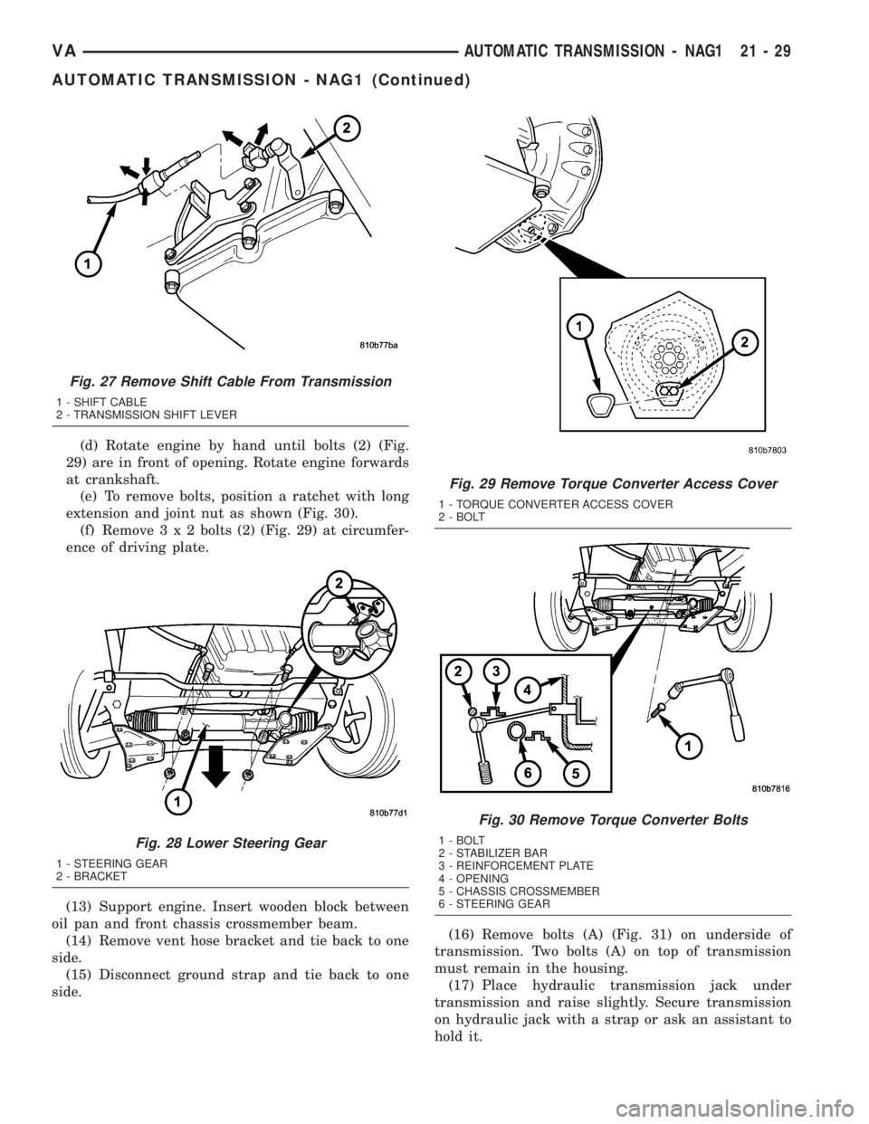
(d) Rotate engine by hand until bolts (2) (Fig.
29) are in front of opening. Rotate engine forwards
at crankshaft.
(e) To remove bolts, position a ratchet with long
extension and joint nut as shown (Fig. 30).
(f) Remove3x2bolts (2) (Fig. 29) at circumfer-
ence of driving plate.
(13) Support engine. Insert wooden block between
oil pan and front chassis crossmember beam.
(14) Remove vent hose bracket and tie back to one
side.
(15) Disconnect ground strap and tie back to one
side.(16) Remove bolts (A) (Fig. 31) on underside of
transmission. Two bolts (A) on top of transmission
must remain in the housing.
(17) Place hydraulic transmission jack under
transmission and raise slightly. Secure transmission
on hydraulic jack with a strap or ask an assistant to
hold it.
Fig. 27 Remove Shift Cable From Transmission
1 - SHIFT CABLE
2 - TRANSMISSION SHIFT LEVER
Fig. 28 Lower Steering Gear
1 - STEERING GEAR
2 - BRACKET
Fig. 29 Remove Torque Converter Access Cover
1 - TORQUE CONVERTER ACCESS COVER
2 - BOLT
Fig. 30 Remove Torque Converter Bolts
1 - BOLT
2 - STABILIZER BAR
3 - REINFORCEMENT PLATE
4 - OPENING
5 - CHASSIS CROSSMEMBER
6 - STEERING GEAR
VAAUTOMATIC TRANSMISSION - NAG1 21 - 29
AUTOMATIC TRANSMISSION - NAG1 (Continued)
Page 919 of 1232
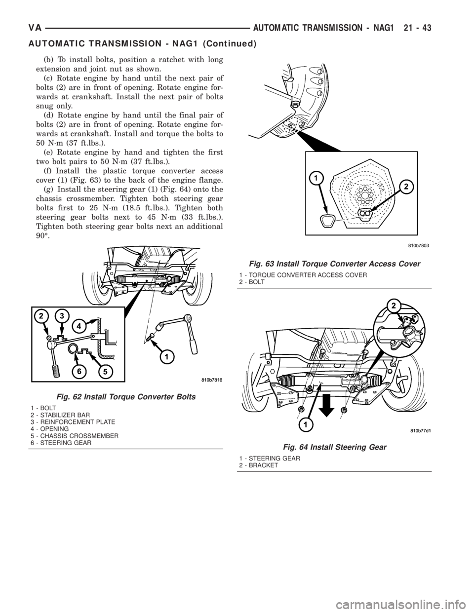
(b) To install bolts, position a ratchet with long
extension and joint nut as shown.
(c) Rotate engine by hand until the next pair of
bolts (2) are in front of opening. Rotate engine for-
wards at crankshaft. Install the next pair of bolts
snug only.
(d) Rotate engine by hand until the final pair of
bolts (2) are in front of opening. Rotate engine for-
wards at crankshaft. Install and torque the bolts to
50 N´m (37 ft.lbs.).
(e) Rotate engine by hand and tighten the first
two bolt pairs to 50 N´m (37 ft.lbs.).
(f) Install the plastic torque converter access
cover (1) (Fig. 63) to the back of the engine flange.
(g) Install the steering gear (1) (Fig. 64) onto the
chassis crossmember. Tighten both steering gear
bolts first to 25 N´m (18.5 ft.lbs.). Tighten both
steering gear bolts next to 45 N´m (33 ft.lbs.).
Tighten both steering gear bolts next an additional
90É.
Fig. 62 Install Torque Converter Bolts
1 - BOLT
2 - STABILIZER BAR
3 - REINFORCEMENT PLATE
4 - OPENING
5 - CHASSIS CROSSMEMBER
6 - STEERING GEAR
Fig. 63 Install Torque Converter Access Cover
1 - TORQUE CONVERTER ACCESS COVER
2 - BOLT
Fig. 64 Install Steering Gear
1 - STEERING GEAR
2 - BRACKET
VAAUTOMATIC TRANSMISSION - NAG1 21 - 43
AUTOMATIC TRANSMISSION - NAG1 (Continued)
Page 1002 of 1232
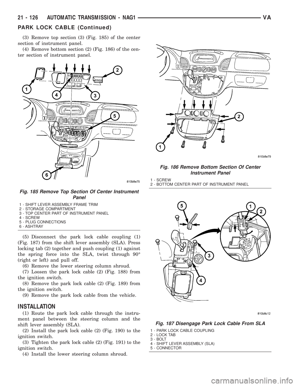
(3) Remove top section (3) (Fig. 185) of the center
section of instrument panel.
(4) Remove bottom section (2) (Fig. 186) of the cen-
ter section of instrument panel.
(5) Disconnect the park lock cable coupling (1)
(Fig. 187) from the shift lever assembly (SLA). Press
locking tab (2) together and push coupling (1) against
the spring force into the SLA, twist through 90É
(right or left) and pull off.
(6) Remove the lower steering column shroud.
(7) Loosen the park lock cable (2) (Fig. 188) from
the ignition switch.
(8) Remove the park lock cable (2) (Fig. 189) from
the ignition switch.
(9) Remove the park lock cable from the vehicle.
INSTALLATION
(1) Route the park lock cable through the instru-
ment panel between the steering column and the
shift lever assembly (SLA).
(2) Install the park lock cable (2) (Fig. 190) to the
ignition switch.
(3) Tighten the park lock cable (2) (Fig. 191) to the
ignition switch.
(4) Install the lower steering column shroud.
Fig. 185 Remove Top Section Of Center Instrument
Panel
1 - SHIFT LEVER ASSEMBLY FRAME TRIM
2 - STORAGE COMPARTMENT
3 - TOP CENTER PART OF INSTRUMENT PANEL
4 - SCREW
5 - PLUG CONNECTIONS
6 - ASHTRAY
Fig. 186 Remove Bottom Section Of Center
Instrument Panel
1 - SCREW
2 - BOTTOM CENTER PART OF INSTRUMENT PANEL
Fig. 187 Disengage Park Lock Cable From SLA
1 - PARK LOCK CABLE COUPLING
2 - LOCK TAB
3 - BOLT
4 - SHIFT LEVER ASSEMBLY (SLA)
5 - CONNECTOR
21 - 126 AUTOMATIC TRANSMISSION - NAG1VA
PARK LOCK CABLE (Continued)
Page 1029 of 1232
STANDARD PROCEDURE - TIRE ROTATION
Tires on the front and rear axles operate at differ-
ent loads and perform different steering, driving, and
braking functions. For these reasons, the tires wear
at unequal rates. They may also develop irregular
wear patterns. These effects can be reduced by rotat-
ing the tires according to the maintenance schedule
in the Owners Manual. This will improve tread life,
traction and maintain a smooth quiet ride.
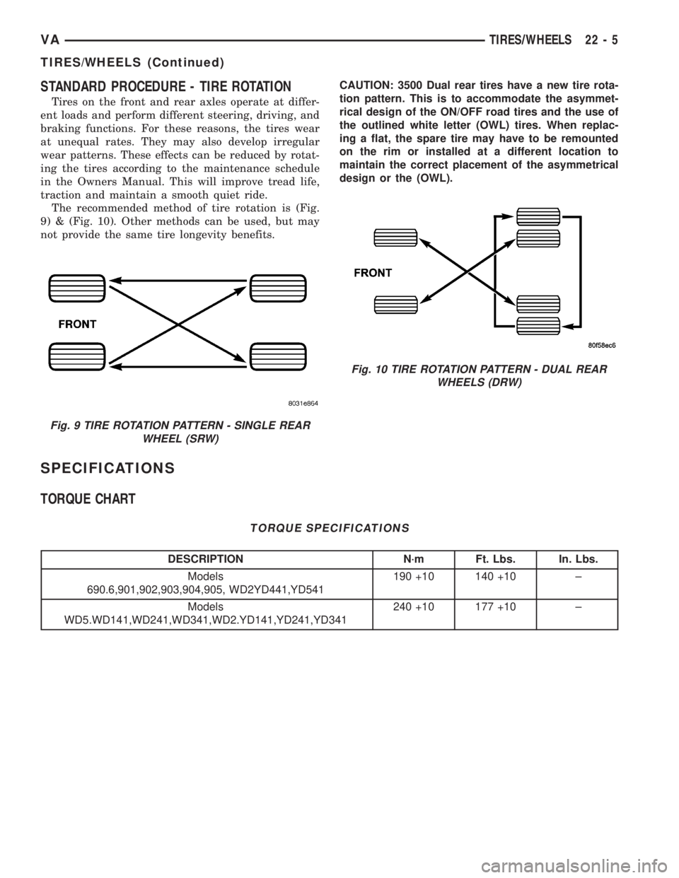
The recommended method of tire rotation is (Fig.
9) & (Fig. 10). Other methods can be used, but may
not provide the same tire longevity benefits.CAUTION: 3500 Dual rear tires have a new tire rota-
tion pattern. This is to accommodate the asymmet-
rical design of the ON/OFF road tires and the use of
the outlined white letter (OWL) tires. When replac-
ing a flat, the spare tire may have to be remounted
on the rim or installed at a different location to
maintain the correct placement of the asymmetrical
design or the (OWL).
SPECIFICATIONS
TORQUE CHART
TORQUE SPECIFICATIONS
DESCRIPTION N´m Ft. Lbs. In. Lbs.
Models
690.6,901,902,903,904,905, WD2YD441,YD541190 +10 140 +10 ±
Models
WD5.WD141,WD241,WD341,WD2.YD141,YD241,YD341240 +10 177 +10 ±
Fig. 9 TIRE ROTATION PATTERN - SINGLE REAR
WHEEL (SRW)
Fig. 10 TIRE ROTATION PATTERN - DUAL REAR
WHEELS (DRW)
VATIRES/WHEELS 22 - 5
TIRES/WHEELS (Continued)
Page 1031 of 1232
shown on the tire placard. For continuous speeds in
excess of 120 km/h (75 mph), tires must be inflated
to the maximum pressure specified on the tire side-
wall.
Vehicles loaded to the maximum capacity should
not be driven at continuous speeds above 75 mph
(120 km/h).
For emergency vehicles that are driven at speeds
over 90 mph (144 km/h), special high speed tires
must be used. Consult tire manufacturer for correct
inflation pressure recommendations.
DESCRIPTION - REPLACEMENT TIRES
The original equipment tires provide a proper bal-
ance of many characteristics such as:
²Ride
²Noise
²Handling
²Durability
²Tread life
²Traction
²Rolling resistance
²Speed capability
It is recommended that tires equivalent to the orig-
inal equipment tires be used when replacement is
needed.
Failure to use equivalent replacement tires may
adversely affect the safety and handling of the vehi-
cle.
The use of oversize tires may cause interference
with vehicle components. Under extremes of suspen-
sion and steering travel, interference with vehicle
components may cause tire damage.
WARNING: FAILURE TO EQUIP THE VEHICLE WITH
TIRES HAVING ADEQUATE SPEED CAPABILITY
CAN RESULT IN SUDDEN TIRE FAILURE.
DESCRIPTION - TIRE INFLATION PRESSURES
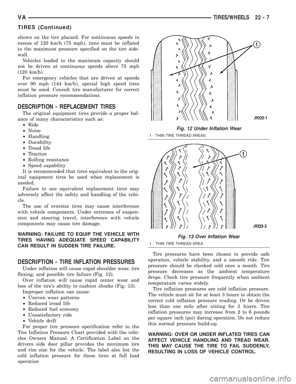
Under inflation will cause rapid shoulder wear, tire
flexing, and possible tire failure (Fig. 12).
Over inflation will cause rapid center wear and
loss of the tire's ability to cushion shocks (Fig. 13).
Improper inflation can cause:
²Uneven wear patterns
²Reduced tread life
²Reduced fuel economy
²Unsatisfactory ride
²Vehicle drift
For proper tire pressure specification refer to the
Tire Inflation Pressure Chart provided with the vehi-
cles Owners Manual. A Certification Label on the
drivers side door pillar provides the minimum tire
and rim size for the vehicle. The label also list the
cold inflation pressure for these tires at full load
operationTire pressures have been chosen to provide safe
operation, vehicle stability, and a smooth ride. Tire
pressure should be checked cold once a month. Tire
pressure decreases as the ambient temperature
drops. Check tire pressure frequently when ambient
temperature varies widely.
Tire inflation pressures are cold inflation pressure.
The vehicle must sit for at least 3 hours to obtain the
correct cold inflation pressure reading. Or be driven
less than one mile after sitting for 3 hours. Tire
inflation pressures may increase from 2 to 6 pounds
per square inch (psi) during operation. Do not reduce
this normal pressure build-up.
WARNING: OVER OR UNDER INFLATED TIRES CAN
AFFECT VEHICLE HANDLING AND TREAD WEAR.
THIS MAY CAUSE THE TIRE TO FAIL SUDDENLY,
RESULTING IN LOSS OF VEHICLE CONTROL.
Fig. 12 Under Inflation Wear
1 - THIN TIRE THREAD AREAS
Fig. 13 Over Inflation Wear
1 - THIN TIRE THREAD AREA
VATIRES/WHEELS 22 - 7
TIRES (Continued)
Page 1042 of 1232
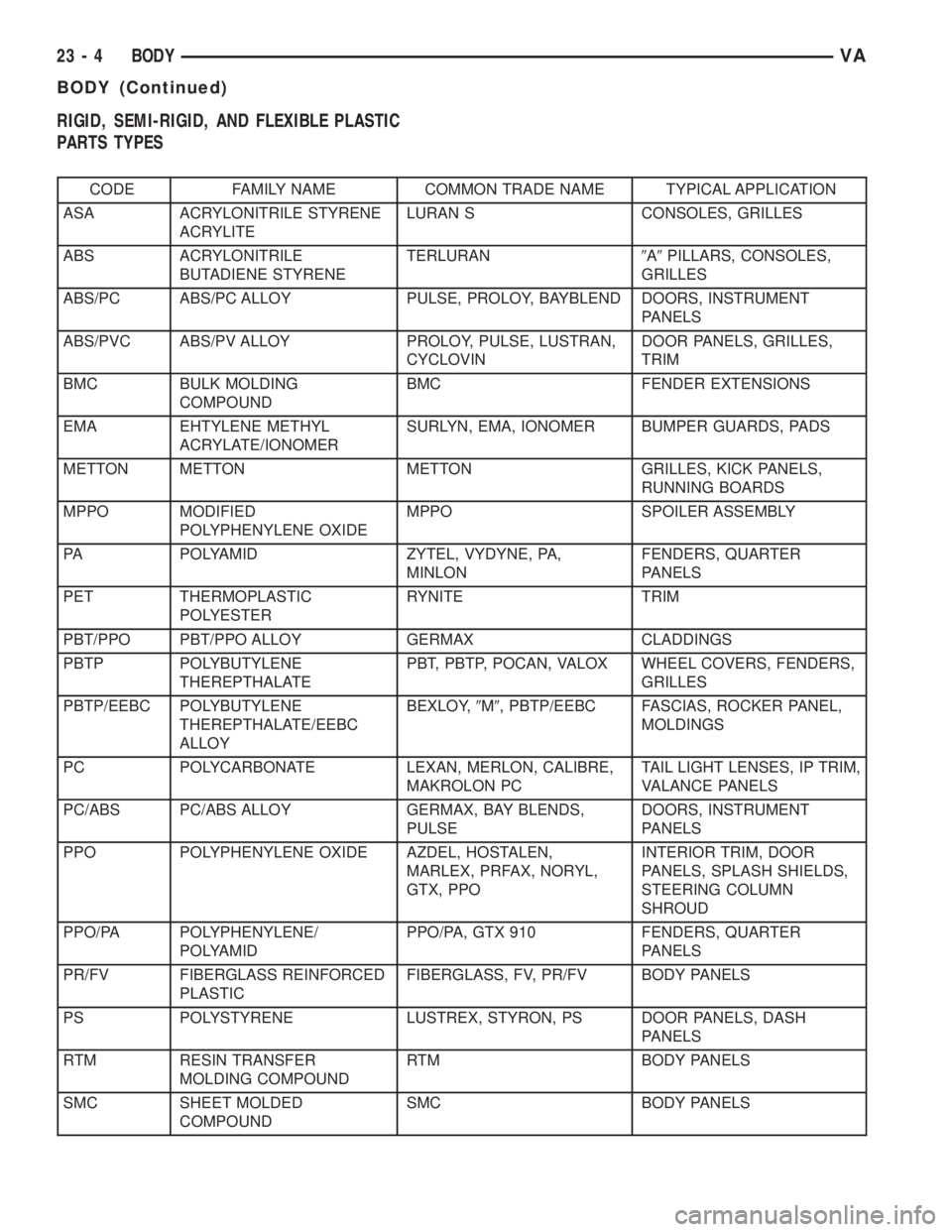
RIGID, SEMI-RIGID, AND FLEXIBLE PLASTIC
PARTS TYPES
CODE FAMILY NAME COMMON TRADE NAME TYPICAL APPLICATION
ASA ACRYLONITRILE STYRENE
ACRYLITELURAN S CONSOLES, GRILLES
ABS ACRYLONITRILE
BUTADIENE STYRENETERLURAN9A9PILLARS, CONSOLES,
GRILLES
ABS/PC ABS/PC ALLOY PULSE, PROLOY, BAYBLEND DOORS, INSTRUMENT
PANELS
ABS/PVC ABS/PV ALLOY PROLOY, PULSE, LUSTRAN,
CYCLOVINDOOR PANELS, GRILLES,
TRIM
BMC BULK MOLDING
COMPOUNDBMC FENDER EXTENSIONS
EMA EHTYLENE METHYL
ACRYLATE/IONOMERSURLYN, EMA, IONOMER BUMPER GUARDS, PADS
METTON METTON METTON GRILLES, KICK PANELS,
RUNNING BOARDS
MPPO MODIFIED
POLYPHENYLENE OXIDEMPPO SPOILER ASSEMBLY
PA POLYAMID ZYTEL, VYDYNE, PA,
MINLONFENDERS, QUARTER
PANELS
PET THERMOPLASTIC
POLYESTERRYNITE TRIM
PBT/PPO PBT/PPO ALLOY GERMAX CLADDINGS
PBTP POLYBUTYLENE
THEREPTHALATEPBT, PBTP, POCAN, VALOX WHEEL COVERS, FENDERS,
GRILLES
PBTP/EEBC POLYBUTYLENE
THEREPTHALATE/EEBC
ALLOYBEXLOY,9M9, PBTP/EEBC FASCIAS, ROCKER PANEL,
MOLDINGS
PC POLYCARBONATE LEXAN, MERLON, CALIBRE,
MAKROLON PCTAIL LIGHT LENSES, IP TRIM,
VALANCE PANELS
PC/ABS PC/ABS ALLOY GERMAX, BAY BLENDS,
PULSEDOORS, INSTRUMENT
PANELS
PPO POLYPHENYLENE OXIDE AZDEL, HOSTALEN,
MARLEX, PRFAX, NORYL,
GTX, PPOINTERIOR TRIM, DOOR
PANELS, SPLASH SHIELDS,
STEERING COLUMN
SHROUD
PPO/PA POLYPHENYLENE/
POLYAMIDPPO/PA, GTX 910 FENDERS, QUARTER
PANELS
PR/FV FIBERGLASS REINFORCED
PLASTICFIBERGLASS, FV, PR/FV BODY PANELS
PS POLYSTYRENE LUSTREX, STYRON, PS DOOR PANELS, DASH
PANELS
RTM RESIN TRANSFER
MOLDING COMPOUNDRTM BODY PANELS
SMC SHEET MOLDED
COMPOUNDSMC BODY PANELS
23 - 4 BODYVA
BODY (Continued)