Page 60 of 969

- PREPARATIONAUTOMATIC TRANSMISSION / TRANS
02-3
12 Author�: Date�:
U151E, U151F A/T REPAIR MANUAL (RM1021U)
09527-1701 1Rear Axle Shaft Bearing RemoverAUTOMATIC TRANSAXLE
ASSY(U151E/U151F)
FRONT DIFFERENTIAL
ASSY(U151F)
09550-60010Differential Side Bearing
ReplacerFRONT DIFFERENTIAL
ASSY(U151E)
(09951-00490)Replacer 49FRONT DIFFERENTIAL
ASSY(U151E)
09564-3201 1Differential Preload AdaptorFRONT DIFFERENTIAL
ASSY(U151E)
FRONT DIFFERENTIAL
ASSY(U151F)
09608-10010Steering Knuckle Oil Seal
ReplacerFRONT DIFFERENTIAL
ASSY(U151E)
FRONT DIFFERENTIAL
ASSY(U151F)
09649-17010Steering Knuckle ToolAUTOMATIC TRANSAXLE
ASSY(U151E/U151F)
FRONT DIFFERENTIAL
ASSY(U151F)
09710-30050Suspension Arm Bushing ReplacerFRONT DIFFERENTIAL
ASSY(U151E)
09726-40010Lower Control Shaft Bearing
ReplacerUNDERDRIVE PLANETARY GEAR
ASSY(U151E/U151F)
09930-00010Drive Shaft Nut ChiselUNDERDRIVE PLANETARY GEAR
ASSY(U151E/U151F)
(09931-00010)HandleUNDERDRIVE PLANETARY GEAR
ASSY(U151E/U151F)
(09931-00020)Nut ChiselUNDERDRIVE PLANETARY GEAR
ASSY(U151E/U151F)
09950-00020Bearing RemoverFRONT DIFFERENTIAL
ASSY(U151E)
AUTOMATIC TRANSAXLE
ASSY(U151E/U151F)
UNDERDRIVE PLANETARY GEAR
ASSY(U151E/U151F)
FRONT DIFFERENTIAL
ASSY(U151F)
Page 352 of 969
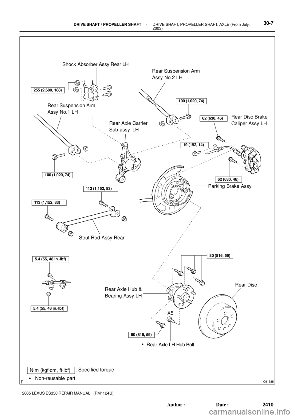
C91585
NVm (kgfVcm, ftVlbf): Specified torque
� Non-reusable partShock Absorber Assy Rear LH
Rear Suspension Arm
Assy No.2 LH
Rear Disc Brake
Caliper Assy LH Rear Axle Carrier
Sub-assy LH
Parking Brake Assy
Rear Axle Hub &
Bearing Assy LHRear Disc Strut Rod Assy Rear
100 (1,020, 74)
62 (630, 46)
100 (1,020, 74)
113 (1,152, 83)
113 (1,152, 83)
5.4 (55, 48 in.Vlbf)
5.4 (55, 48 in.Vlbf)
Rear Axle LH Hub Bolt
80 (816, 59)
X5
�
255 (2,600, 188)
19 (192, 14)
62 (630, 46)
80 (816, 59)
Rear Suspension Arm
Assy No.1 LH
- DRIVE SHAFT / PROPELLER SHAFTDRIVE SHAFT, PROPELLER SHAFT, AXLE (From July,
2003)30-7
2410 Author�: Date�:
2005 LEXUS ES330 REPAIR MANUAL (RM1124U)
Page 374 of 969
3006J-06
C83017
C83018
C83019
- DRIVE SHAFT / PROPELLER SHAFTREAR AXLE CARRIER SUB-ASSY LH
30-29
2432 Author�: Date�:
2005 LEXUS ES330 REPAIR MANUAL (RM1124U)
REAR AXLE CARRIER SUB-ASSY LH
REPLACEMENT
HINT:
�COMPONENTS: See page 30-4
�Replace the RH side by the same procedures with the LH side.
1. REMOVE REAR WHEEL
2. REMOVE STRUT ROD ASSY REAR (SEE PAGE 27-18)
3. DISCONNECT REAR DISC BRAKE CALIPER ASSY LH (SEE PAGE 30-26)
4. REMOVE REAR DISC
5. DISCONNECT SKID CONTROL SENSOR WIRE
6. REMOVE REAR AXLE HUB & BEARING ASSY LH (SEE PAGE 30-26)
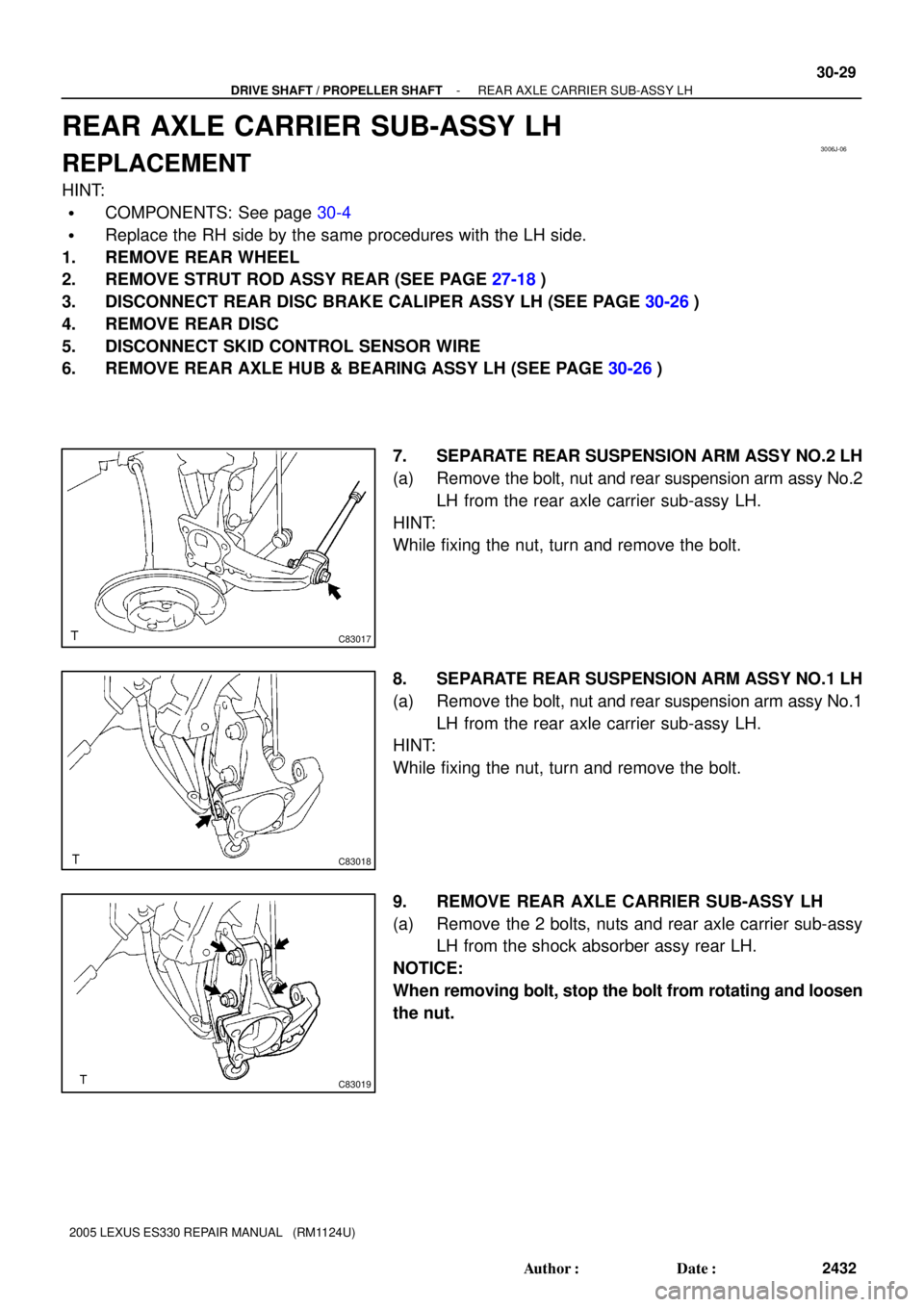
7. SEPARATE REAR SUSPENSION ARM ASSY NO.2 LH
(a) Remove the bolt, nut and rear suspension arm assy No.2
LH from the rear axle carrier sub-assy LH.
HINT:
While fixing the nut, turn and remove the bolt.
8. SEPARATE REAR SUSPENSION ARM ASSY NO.1 LH
(a) Remove the bolt, nut and rear suspension arm assy No.1
LH from the rear axle carrier sub-assy LH.
HINT:
While fixing the nut, turn and remove the bolt.
9. REMOVE REAR AXLE CARRIER SUB-ASSY LH
(a) Remove the 2 bolts, nuts and rear axle carrier sub-assy
LH from the shock absorber assy rear LH.
NOTICE:
When removing bolt, stop the bolt from rotating and loosen
the nut.
Page 375 of 969
C83019
C83018
C83017
30-30
- DRIVE SHAFT / PROPELLER SHAFTREAR AXLE CARRIER SUB-ASSY LH
2433 Author�: Date�:
2005 LEXUS ES330 REPAIR MANUAL (RM1124U)
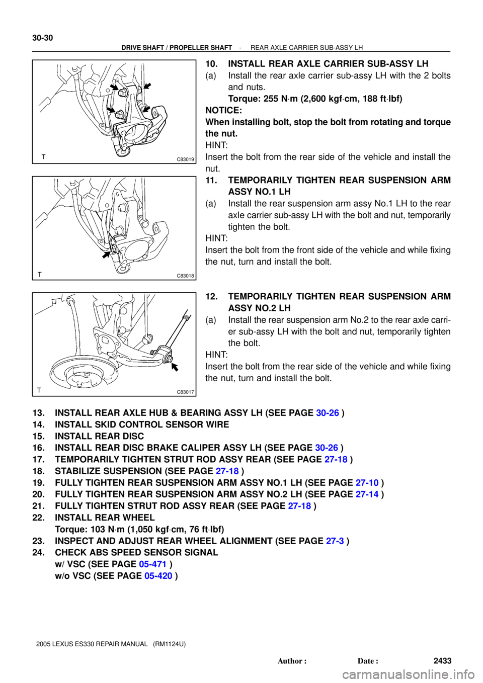
10. INSTALL REAR AXLE CARRIER SUB-ASSY LH
(a) Install the rear axle carrier sub-assy LH with the 2 bolts
and nuts.
Torque: 255 NVm (2,600 kgfVcm, 188 ftVlbf)
NOTICE:
When installing bolt, stop the bolt from rotating and torque
the nut.
HINT:
Insert the bolt from the rear side of the vehicle and install the
nut.
11. TEMPORARILY TIGHTEN REAR SUSPENSION ARM
ASSY NO.1 LH
(a) Install the rear suspension arm assy No.1 LH to the rear
axle carrier sub-assy LH with the bolt and nut, temporarily
tighten the bolt.
HINT:
Insert the bolt from the front side of the vehicle and while fixing
the nut, turn and install the bolt.
12. TEMPORARILY TIGHTEN REAR SUSPENSION ARM
ASSY NO.2 LH
(a) Install the rear suspension arm No.2 to the rear axle carri-
er sub-assy LH with the bolt and nut, temporarily tighten
the bolt.
HINT:
Insert the bolt from the rear side of the vehicle and while fixing
the nut, turn and install the bolt.
13. INSTALL REAR AXLE HUB & BEARING ASSY LH (SEE PAGE 30-26)
14. INSTALL SKID CONTROL SENSOR WIRE
15. INSTALL REAR DISC
16. INSTALL REAR DISC BRAKE CALIPER ASSY LH (SEE PAGE 30-26)
17. TEMPORARILY TIGHTEN STRUT ROD ASSY REAR (SEE PAGE 27-18)
18. STABILIZE SUSPENSION (SEE PAGE 27-18)
19. FULLY TIGHTEN REAR SUSPENSION ARM ASSY NO.1 LH (SEE PAGE 27-10)
20. FULLY TIGHTEN REAR SUSPENSION ARM ASSY NO.2 LH (SEE PAGE 27-14)
21. FULLY TIGHTEN STRUT ROD ASSY REAR (SEE PAGE 27-18)
22. INSTALL REAR WHEEL
Torque: 103 NVm (1,050 kgfVcm, 76 ftVlbf)
23. INSPECT AND ADJUST REAR WHEEL ALIGNMENT (SEE PAGE 27-3)
24. CHECK ABS SPEED SENSOR SIGNAL
w/ VSC (SEE PAGE 05-471)
w/o VSC (SEE PAGE 05-420)
Page 394 of 969
A84926
N´m (kgf´cm, ft´lbf)
: Specified torque
49 (500, 36)
74 (755, 55)
75 (765, 55)
Steering Intermediate Shaft Assy
Front Suspension Arm
Sub-assy Lower No. 1 LH
Front Axle Hub LH Nut
Tie Rod Assy LH
Speed Sensor Front LH
� Cotter Pin
294 (2,998, 217)�
62 (633, 46)
Exhaust Pipe Assy Front
Exhaust Pipe No. 1
Support Bracket Front
8.0 (82, 71 in.Vlbf)
75 (765, 55)
� Exhaust Pipe Gasket
� Non-reusable part33 (337, 24)
35 (360, 26)
Front Stabilizer Link
Assy LH
35 (360, 26)
�
56 (571, 41)
� Exhaust Pipe
Gasket
33 (337, 24)
Exhaust Pipe No. 1
Support Bracket Rear
�
� Exhaust Pipe
Gasket
62 (633, 46)
14-18
- ENGINE MECHANICALPARTIAL ENGINE ASSY (3MZ-FE)
2110 Author�: Date�:
2005 LEXUS ES330 REPAIR MANUAL (RM1124U)
Page 395 of 969
A84927N´m (kgf´cm, ft´lbf)
: Specified torque
7.8 (80, 69 in.Vlbf)
43 (439, 32)
87 (887, 64)
Vane Pump V Belt
Vane Pump Assy
Front Frame Assy
Frame Side Rail Plate
Sub-assy RH
Frame Side Rail Plate
Sub-assy LHFront Suspension Member
Brace Rear RH
Front Suspension Member
Brace Rear LH
43 (439, 32)
95 (969, 70)
85 (867, 63)
32 (326, 24)
95 (969, 70)
85 (867, 63)
32 (326, 24)
- ENGINE MECHANICALPARTIAL ENGINE ASSY (3MZ-FE)
14-19
2111 Author�: Date�:
2005 LEXUS ES330 REPAIR MANUAL (RM1124U)
Page 407 of 969

A59877
A59878
A36439
- ENGINE MECHANICALPARTIAL ENGINE ASSY (3MZ-FE)
14-31
2123 Author�: Date�:
2005 LEXUS ES330 REPAIR MANUAL (RM1124U)
51. SEPARATE FRONT SUSPENSION ARM SUB-ASSY LOWER NO.1 LH (See page 30-8)
52. SEPARATE FRONT SUSPENSION ARM SUB-ASSY LOWER NO.1 RH
HINT:
Perform the same procedure as above on the opposite side.
53. SEPARATE FRONT AXLE ASSY LH (See page 30-8)
54. SEPARATE FRONT AXLE ASSY RH
HINT:
Perform the same procedure as above on the opposite side.
55. SEPARATE STEERING INTERMEDIATE SHAFT ASSY (See page 51-21)
56. REMOVE ENGINE ASSEMBLY WITH TRANSAXLE
(a) Set the engine lifter.
(b) Remove the 4 bolts and 2 nuts, then remove the frame
side rail plate RH and LH.
(c) Remove the 4 bolts and 2 nuts, then remove the front sus-
pension member brace rear RH and LH.
(d) Carefully remove the engine assembly from the vehicle.
(e) Install the engine hanger No. 2 in the correct direction as
shown in the illustration.
Torque: 20 NVm (199 kgfVcm, 14 ftVlbf)
HINT:
Engine hanger No. 212282-20020
Bolt91621-60822
(f) Attach the engine sling and hang the engine assembly
with the chain block.
57. REMOVE VANE PUMP V BELT (See page 14-5)
Page 413 of 969
A59877
BNut
A
BNut
A
A59878
Nut
D
CNut
D
C
- ENGINE MECHANICALPARTIAL ENGINE ASSY (3MZ-FE)
14-37
2129 Author�: Date�:
2005 LEXUS ES330 REPAIR MANUAL (RM1124U)
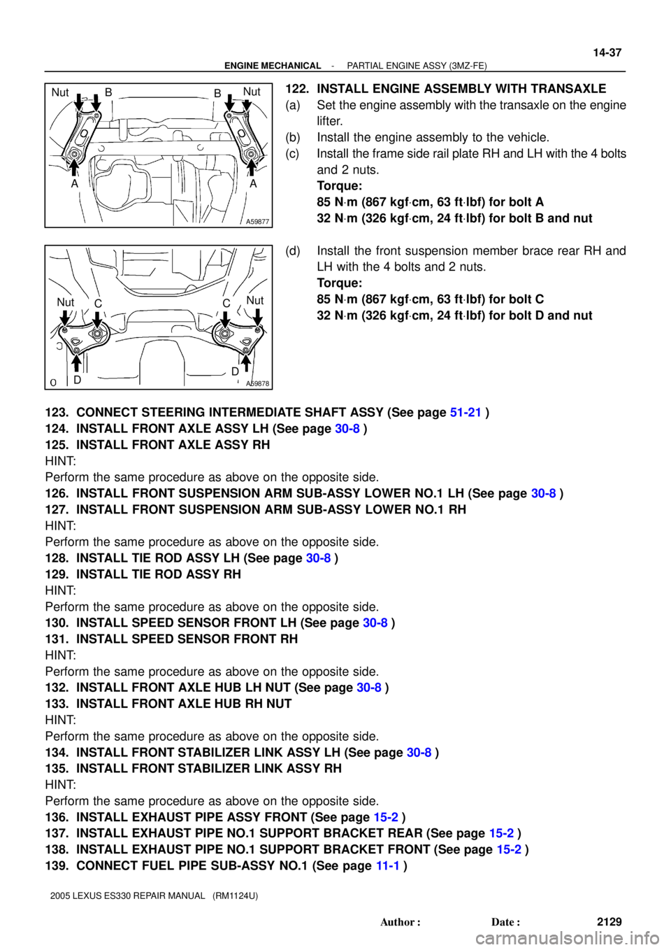
122. INSTALL ENGINE ASSEMBLY WITH TRANSAXLE
(a) Set the engine assembly with the transaxle on the engine
lifter.
(b) Install the engine assembly to the vehicle.
(c) Install the frame side rail plate RH and LH with the 4 bolts
and 2 nuts.
Torque:
85 NVm (867 kgfVcm, 63 ftVlbf) for bolt A
32 NVm (326 kgfVcm, 24 ftVlbf) for bolt B and nut
(d) Install the front suspension member brace rear RH and
LH with the 4 bolts and 2 nuts.
Torque:
85 NVm (867 kgfVcm, 63 ftVlbf) for bolt C
32 NVm (326 kgfVcm, 24 ftVlbf) for bolt D and nut
123. CONNECT STEERING INTERMEDIATE SHAFT ASSY (See page 51-21)
124. INSTALL FRONT AXLE ASSY LH (See page 30-8)
125. INSTALL FRONT AXLE ASSY RH
HINT:
Perform the same procedure as above on the opposite side.
126. INSTALL FRONT SUSPENSION ARM SUB-ASSY LOWER NO.1 LH (See page 30-8)
127. INSTALL FRONT SUSPENSION ARM SUB-ASSY LOWER NO.1 RH
HINT:
Perform the same procedure as above on the opposite side.
128. INSTALL TIE ROD ASSY LH (See page 30-8)
129. INSTALL TIE ROD ASSY RH
HINT:
Perform the same procedure as above on the opposite side.
130. INSTALL SPEED SENSOR FRONT LH (See page 30-8)
131. INSTALL SPEED SENSOR FRONT RH
HINT:
Perform the same procedure as above on the opposite side.
132. INSTALL FRONT AXLE HUB LH NUT (See page 30-8)
133. INSTALL FRONT AXLE HUB RH NUT
HINT:
Perform the same procedure as above on the opposite side.
134. INSTALL FRONT STABILIZER LINK ASSY LH (See page 30-8)
135. INSTALL FRONT STABILIZER LINK ASSY RH
HINT:
Perform the same procedure as above on the opposite side.
136. INSTALL EXHAUST PIPE ASSY FRONT (See page 15-2)
137. INSTALL EXHAUST PIPE NO.1 SUPPORT BRACKET REAR (See page 15-2)
138. INSTALL EXHAUST PIPE NO.1 SUPPORT BRACKET FRONT (See page 15-2)
139. CONNECT FUEL PIPE SUB-ASSY NO.1 (See page 11-1)