Page 72 of 969

TORQUE SPECIFICATION
Part TightenedNVmkgfVcmftVlbf
Differential")
0305L-1 1
03-8
- SERVICE SPECIFICATIONSAUTOMATIC TRANSMISSION / TRANSAXLE
24 Author�: Date�:
U151E, U151F A/T REPAIR MANUAL (RM1021U)
TORQUE SPECIFICATION
Part TightenedNVmkgfVcmftVlbf
Differential gear lube apply tube x Transaxle housing9.810087 in.Vlbf
Front planetary gear lock nut210-3502141-3569155-258
Brake apply tube clamp x Transaxle case5.45548 in.Vlbf
Transaxle case No. 1 plug x Transaxle rear cover7.47565 in.Vlbf
Transaxle rear cover x Transaxle case Bolt A
Other bolt19
25190
25014
18
Pawl shaft clamp x Transaxle case9.810087 in.Vlbf
Oil pump assy x Transaxle case2222616
Transaxle housing x Transaxle case Bolt A
Bolt B
Bolt C
Bolt D25
33
29
22255
337
295
22618
24
21
16
Automatic transmission case plug x Transaxle housing7.47565 in.Vlbf
Automatic transmission case plug x Transaxle case7.47565 in.Vlbf
Parking lock pawl bracket x Transaxle case2020515
Manual detent spring x Transaxle case Bolt A
Bolt B20
12205
12015
9
Transmission wire x Transaxle housing5.45548 in.Vlbf
Transmission valve body x Transaxle case1111 08
ATF temperature sensor clamp x Transmission valve body6.66758 inVlbf
Valve body oil strainer assy x Transmission valve body1111 08
Automatic transaxle oil pan sub-assy x Transaxle case7.88069 in.Vlbf
Drain plug x Automatic transaxle oil pan sub-assy4950036
Speed sensor x Transaxle case1111 58
Oil cooler tube union x Transaxle case Union
Elbow27
27276
27620
20
Park/neutral start switch x nut6.97061 in.Vlbf
Park/neutral start switch x Bolt5.45548 in.Vlbf
Park/neutral start switch x Control shaft lever131309
Speedometer driven hole cover sub-assy x Transaxle case6.97061
Oil pump body x Stator shaft assy9.810087 in.Vlbf
Line pressure control solenoid assy x Transmission valve body assy6.66758 in.Vlbf
Shift solenoid valve SL1x Transmission valve body assy6.66758 in.Vlbf
Shift solenoid valve SL2x Transmission valve body assy10.811 08
Shift solenoid valve SL3x Transmission valve body assy6.66758 in.Vlbf
Shift solenoid valve S4x Transmission valve body assy10.811 08
Shift solenoid valve DSL x Transmission valve body assy10.811 08
Front differential case x Front differential ring gear95.197070
Page 74 of 969
: Specified torque
� Non-reusable partO-Ring �
� Precoated part�x 18
Automatic Transaxle
Oil Pan Sub-assyAutomatic Transaxle
Oil Pan Gasket Valve Body
Oil Strainer Ass")
C89119
N´m (kgf´cm, ft´lbf): Specified torque
� Non-reusable partO-Ring �
� Precoated part�x 18
Automatic Transaxle
Oil Pan Sub-assyAutomatic Transaxle
Oil Pan Gasket Valve Body
Oil Strainer AssyOil Cleaner
Magnet
� �
Oil Strainer Gasket
11 (110, 8 )
x 17 Transmission Valve Body Assy
Parking Lock
Rod Sub-assy
Parking Lock
Pawl Bracket
Manual Detent
Spring Sub-assy11 (110, 8)
20 (205, 15)
20 (205, 15)
C-3 Accumulator
Piston
O-Ring �
Compression
Spring
O-Ring �O-Ring �
B-3 Accumulator
Piston Compression Spring
Reverse Clutch
Accumulator PistonCompression Spring
Washer Control Shaft Lever
Nut Stopper Park/ Neutral
Position SwitchManual Valve Lever Shaft Oil Seal Manual Valve Lever Shaft Sloted Spring Pin Retainer Spring �Spacer
13 (130, 9)
6.9 (70, 61 in.Vlbf)
5.4 (55, 48 in.Vlbf)
�x 5 O-Ring �x 8O-Ring � Transaxle Apply Tube ClampAutomatic Transaxle
Case Sub-assyTransaxle Rear Cover
x 11
Governor Apply Gasket
Transaxle Case
2nd Brake Gasket Differential Gear
Lube Apply Tube
Brake Drum Gasket
7.4 (75, 65 in.Vlbf)
29 (295, 21)
9.8 (100, 87 in.Vlbf)
25 (255, 18)
Case Plug
Spring
Check Ball
Body
Bolt A: 18.6 (190, 14)
Other bolt: 24.5 (250, 18)
U151E:
x 3
33 (337, 24)
11.8 (120, 9)
7.8 (80, 69 in.Vlbf)
40-2- AUTOMATIC TRANSMISSION / TRANSAUTOMATIC TRANSMISSION /
TRANSAXLE (U151E/U151F)
26 Author�: Date�:
U151E, U151F A/T REPAIR MANUAL (RM1021U)
Page 76 of 969
D26594
O-Ring �
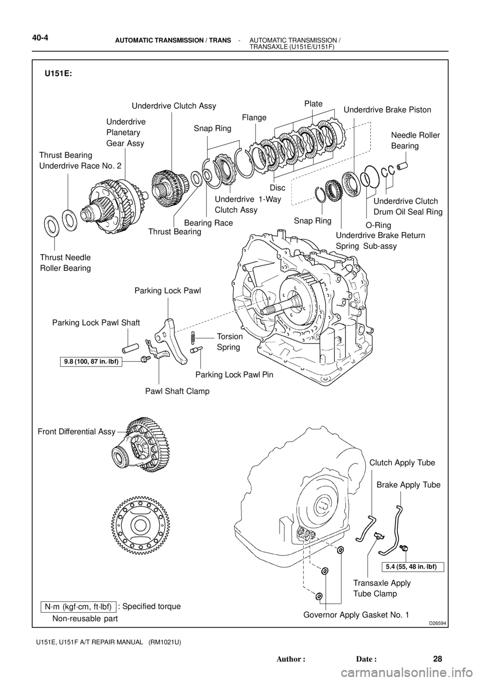
N´m (kgf´cm, ft´lbf): Specified torque
� Non-reusable part Thrust Needle
Roller Bearing Thrust Bearing
Underdrive Race No. 2Underdrive
Planetary
Gear AssyUnderdrive Clutch Assy
Snap RingFlangePlate
Disc
Underdrive 1-Way
Clutch Assy
Bearing Race
Snap Ring
Underdrive Brake Return
Spring Sub-assyUnderdrive Clutch
Drum Oil Seal RingNeedle Roller
Bearing Underdrive Brake Piston
�
Parking Lock Pawl
Parking Lock Pawl Shaft
Torsion
Spring
Parking Lock Pawl Pin
Pawl Shaft Clamp
9.8 (100, 87 in.Vlbf)
Front Differential Assy
Clutch Apply Tube
Brake Apply Tube
Transaxle Apply
Tube Clamp
Governor Apply Gasket No. 1 �
5.4 (55, 48 in.Vlbf)
U151E:
Thrust Bearing 40-4
- AUTOMATIC TRANSMISSION / TRANSAUTOMATIC TRANSMISSION /
TRANSAXLE (U151E/U151F)
28 Author�: Date�:
U151E, U151F A/T REPAIR MANUAL (RM1021U)
Page 78 of 969
: Specified torque
� Non-reusable partO-Ring �
� Precoated part�x 18
Automatic Transaxle
Oil Pan Sub-assyAutomatic Transaxle
Oil Pan Gasket Valve Body
Oil Strainer Ass")
C89116
N´m (kgf´cm, ft´lbf): Specified torque
� Non-reusable partO-Ring �
� Precoated part�x 18
Automatic Transaxle
Oil Pan Sub-assyAutomatic Transaxle
Oil Pan Gasket Valve Body
Oil Strainer AssyOil Cleaner
Magnet
� �
Oil Strainer Gasket
11 (110, 8 )
x 17 Transmission Valve Body Assy
Parking Lock
Rod Sub-assy
Parking Lock
Pawl Bracket
Manual Detent
Spring Sub-assy11 (110, 8)
20.1 (205, 15)
20 (205, 15)
C-3 Accumulator
Piston
O-Ring �
Compression
Spring
O-Ring �O-Ring �
B-3 Accumulator
Piston Compression Spring
Reverse Clutch
Accumulator PistonCompression Spring
Washer Control Shaft Lever
Nut Stopper Park/ Neutral
Position SwitchManual Valve Lever Shaft Oil Seal Manual Valve Lever Shaft Sloted Spring Pin Retainer Spring �Spacer
13 (130, 9)
6.9 (70, 61 in.Vlbf)
5.4 (55, 48 in.Vlbf)
�x 5 O-Ring �x 8O-Ring � Transaxle Apply Tube ClampAutomatic Transaxle
Case Sub-assyTransaxle Rear Cover
x 11
Governor Apply Gasket
Transaxle Case
2nd Brake Gasket Differential Gear
Lube Apply Tube
Brake Drum Gasket
7.4 (75, 65 in.Vlbf)
29.4 (300, 21.7)
9.8 (100, 87 in.Vlbf)Case Plug
Spring
Check Ball
Body
Bolt A: 18.6 (190, 14)
Other bolt: 24.5 (250, 18)
U151F:
x 3
33 (337, 24)
12 (120, 9)
7.8 (80, 69 in.Vlbf)
25 (255, 18)
40-6- AUTOMATIC TRANSMISSION / TRANSAUTOMATIC TRANSMISSION /
TRANSAXLE (U151E/U151F)
30 Author�: Date�:
U151E, U151F A/T REPAIR MANUAL (RM1021U)
Page 80 of 969
C89125
O-Ring �
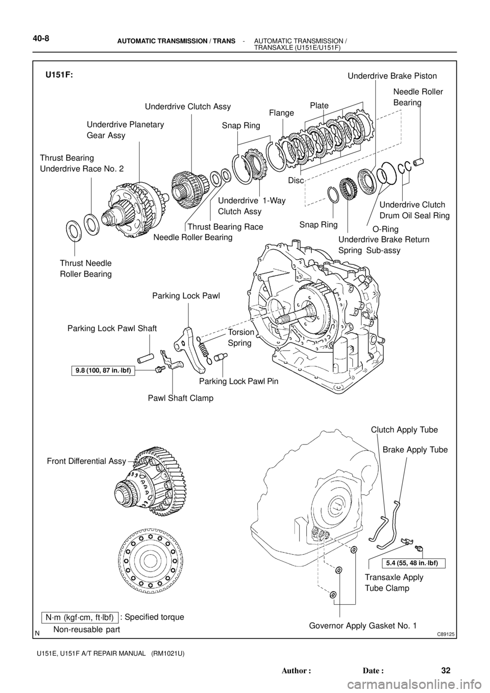
N´m (kgf´cm, ft´lbf): Specified torque
� Non-reusable partThrust Needle
Roller Bearing Thrust Bearing
Underdrive Race No. 2Underdrive Planetary
Gear AssyUnderdrive Clutch Assy
Snap RingFlangePlate
Disc
Underdrive 1-Way
Clutch Assy
Thrust Bearing Race
Needle Roller Bearing
Snap Ring
Underdrive Brake Return
Spring Sub-assyUnderdrive Clutch
Drum Oil Seal RingNeedle Roller
Bearing Underdrive Brake Piston
�
Parking Lock Pawl
Parking Lock Pawl Shaft
Torsion
Spring
Parking Lock Pawl Pin
Pawl Shaft Clamp
9.8 (100, 87 in.Vlbf)
Front Differential Assy
Clutch Apply Tube
Brake Apply Tube
Transaxle Apply
Tube Clamp
Governor Apply Gasket No. 1 �
U151F:
5.4 (55, 48 in.Vlbf)
40-8- AUTOMATIC TRANSMISSION / TRANSAUTOMATIC TRANSMISSION /
TRANSAXLE (U151E/U151F)
32 Author�: Date�:
U151E, U151F A/T REPAIR MANUAL (RM1021U)
Page 200 of 969
4005R-08
D25120
Add if hotOK if hot
- AUTOMATIC TRANSMISSION / TRANSAUTOMATIC TRANSAXLE FLUID
40-1
2516 Author�: Date�:
2005 LEXUS ES330 REPAIR MANUAL (RM1124U)
AUTOMATIC TRANSAXLE FLUID
ON-VEHICLE INSPECTION
1. CHECK THE FLUID LEVEL
HINT:
Drive the vehicle so that the engine and transaxle are at normal
operating temperature.
Fluid temperature: 70 - 80 °C (158 - 176 °F)
(a) Park the vehicle on a level surface and set the parking
brake.
(b) With the engine idling and the brake pedal depressed,
shift the shift lever into all positions from P to L position,
and return to P position.
(c) take out the dipstick and wipe it clean.
(d) Put it back fully into the pipe.
(e) take it out and check that the fluid level is in the HOT posi-
tion.
If there are leaks, it is necessary to repair or replace O-rings,
FIPGs, oil seals, plugs and/or other parts.
Page 206 of 969
4010P-03
C99453
Groove
Neutral
Basic Line
- AUTOMATIC TRANSMISSION / TRANSPARK/NEUTRAL POSITION SWITCH ASSY (U151E)
40-7
2522 Author�: Date�:
2005 LEXUS ES330 REPAIR MANUAL (RM1124U)
ADJUSTMENT
1. INSPECT PARK/NEUTRAL POSITION SWITCH ASSY
(a) Apply the parking brake and turn the ignition switch to ON.
(b) Depress the brake pedal and check that the engine starts only when the shift lever is set in N or P posi-
tion.
(c) Check that the back-up light is lit and the reverse warning buzzer sounds only when the shift lever is
set in R position.
If a failure is found, check the continuity of the park/neutral position switch.
2. ADJUST PARK/NEUTRAL POSITION SWITCH ASSY
(a) Loosen the 2 bolts of park/neutral position switch and set
the shift lever to the N position.
(b) Align the groove with neutral basic line.
(c) Hold the switch in position and tighten the 2 bolts.
Torque: 5.4 NVm (55 kgfVcm, 48 in.Vlbf)
(d) After adjustment, perform the inspection described in
step 1.
Page 247 of 969

PROBLEM SYMPTOMS TABLE
Use the table below to help you find the cause of the problem. The numbers indi")
32039-18
32-2
- BRAKEBRAKE SYSTEM
2436 Author�: Date�:
2005 LEXUS ES330 REPAIR MANUAL (RM1124U)
PROBLEM SYMPTOMS TABLE
Use the table below to help you find the cause of the problem. The numbers indicate the priority of the likely
cause of the problem. Check each part in order. If necessary, replace these parts.
SymptomSuspect AreaSee page
Low pedal or spongy pedal
2. Fluid leaks for brake system
3. Air in brake system
4. Piston seals (Worn or damaged)
5. Master cylinder (Fauly)
6. Booster push rod (Out of adjustment)-
32-4
32-33
32-41
32-21
32-8
32-12
Brake drag
1. Brake pedal free play (Minimal)
2. Parking brake pedal travel (Out of adjustment)
3. Parking brake wire (Sticking)
4. Parking brake shoe clearance (Out of adjustment)
5. Pad (Cracked or distorted)
6. Piston (Stuck)
7. Piston (Frozen)
8. Tension or return spring (Faulty)
9. Booster push rod (Out of adjustment)
10.Vacuum leaks for booster system
11. Master cylinder (Faulty)32-8
32-12
33-2
33-8
33-1 1
33-14
33-2
32-33
32-41
32-33
32-41
32-33
32-41
33-16
32-8
32-12
32-26
32-21
Brake pull
1. Piston (Stuck)
2. Pad (Oily)
3. Piston (Frozen)
4. Disc (Scored)
5. Pad (Cracked or distorted) 32-33
32-41
32-33
32-41
32-33
32-41
32-33
32-41
32-33
32-41
Hard pedal but brake inefficient
1. Fluid leaks for brake system
2. Air in brake system
3. Pad (Worn)
4. Pad (Cracked or distorted)
5. Pad (Oily)
6. Pad (Glanzed)
7. Disc (Scored)
8. Booster push rod (Out of adjustment)
9. Vacuum leaks for booster system-
32-4
32-33
32-41
32-33
32-41
32-33
32-41
32-33
32-41
32-33
32-41
32-8
32-12
32-26