Page 130 of 969

D26387AA
D26414
Flange
Plate Disc
D26466
Snap Ring
D08082
40-58
- AUTOMATIC TRANSMISSION / TRANSAUTOMATIC TRANSAXLE ASSY (U151E/U151F)
82 Author�: Date�:
U151E, U151F A/T REPAIR MANUAL (RM1021U)
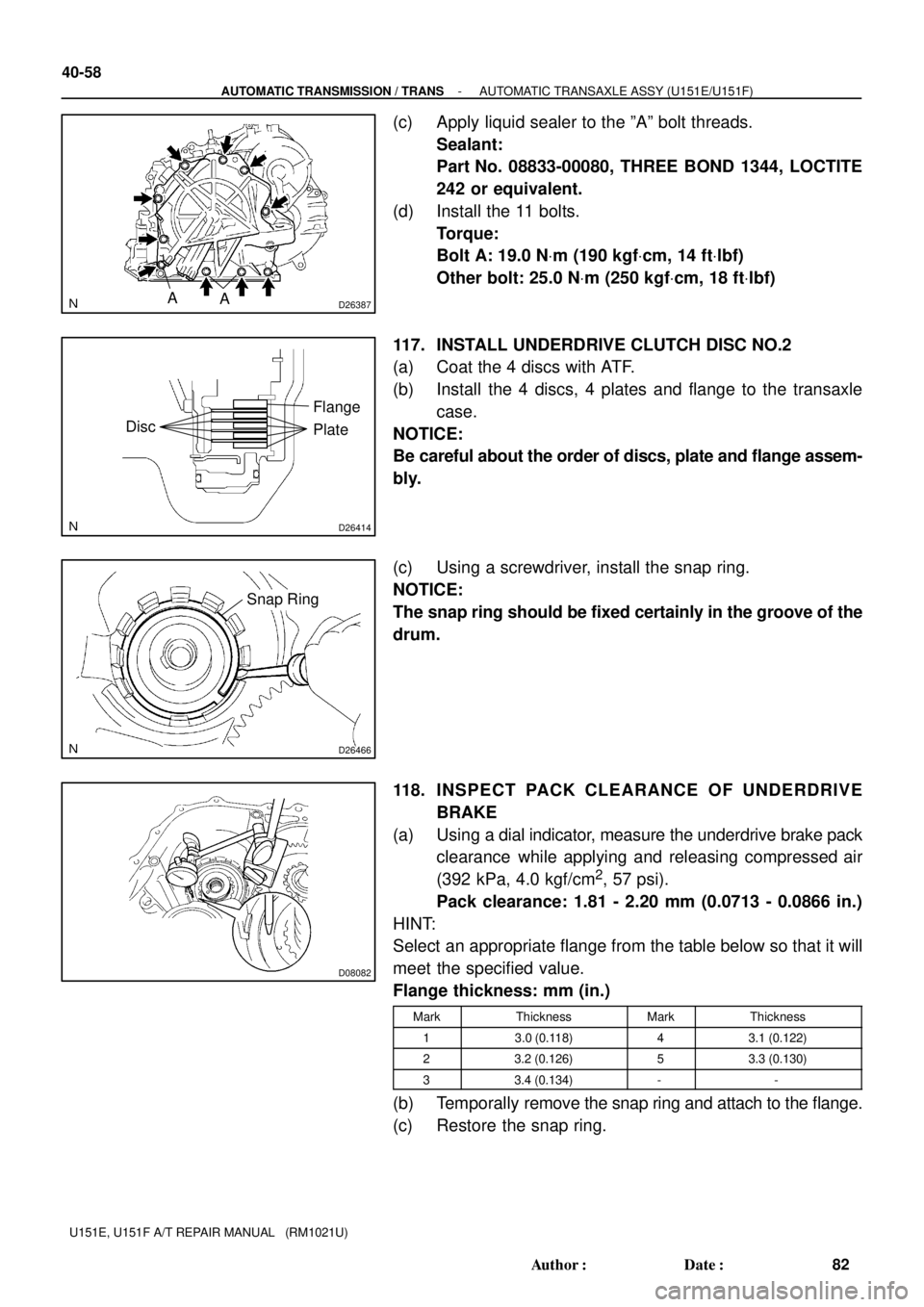
(c) Apply liquid sealer to the ºAº bolt threads.
Sealant:
Part No. 08833-00080, THREE BOND 1344, LOCTITE
242 or equivalent.
(d) Install the 11 bolts.
Torque:
Bolt A: 19.0 NVm (190 kgfVcm, 14 ftVlbf)
Other bolt: 25.0 NVm (250 kgfVcm, 18 ftVlbf)
117. INSTALL UNDERDRIVE CLUTCH DISC NO.2
(a) Coat the 4 discs with ATF.
(b) Install the 4 discs, 4 plates and flange to the transaxle
case.
NOTICE:
Be careful about the order of discs, plate and flange assem-
bly.
(c) Using a screwdriver, install the snap ring.
NOTICE:
The snap ring should be fixed certainly in the groove of the
drum.
118. INSPECT PACK CLEARANCE OF UNDERDRIVE
BRAKE
(a) Using a dial indicator, measure the underdrive brake pack
clearance while applying and releasing compressed air
(392 kPa, 4.0 kgf/cm
2, 57 psi).
Pack clearance: 1.81 - 2.20 mm (0.0713 - 0.0866 in.)
HINT:
Select an appropriate flange from the table below so that it will
meet the specified value.
Flange thickness: mm (in.)
MarkThicknessMarkThickness
13.0 (0.118)43.1 (0.122)
23.2 (0.126)53.3 (0.130)
33.4 (0.134)--
(b) Temporally remove the snap ring and attach to the flange.
(c) Restore the snap ring.
Page 137 of 969

D25608
C
C
CAB2WD:
4WD:
B
D
C CC
CB
B
A
A
D08091
D03631
D26468
SST
- AUTOMATIC TRANSMISSION / TRANSAUTOMATIC TRANSAXLE ASSY (U151E/U151F)
40-65
89 Author�: Date�:
U151E, U151F A/T REPAIR MANUAL (RM1021U)
(c) Install the transaxle housing and 16 bolts to the transaxle
case.
Torque:
Bolt A: 25 NVm (255 kgfVcm, 18 ftVlbf)
Bolt B: 33 NVm (337 kgfVcm, 24 ftVlbf)
Bolt C: 29 NVm (295 kgfVcm, 21 ftVlbf)
Bolt D: 22 NVm (226 kgfVcm, 16.0 ftVlbf)
HINT:
Apply seal packing or equivalent to the bolt A and D.
Seal packing:
THREE BOND 2403 or equivalent
Bolt length:
Bolt A: 50 mm (1.969 in.)
Bolt B: 50 mm (1.969 in.)
Bolt C: 42 mm (1.654 in.)
Bolt D: 72 mm (2.835 in.)
NOTICE:
Because the bolt A is a seal bolt, apply the seal packing to
new bolts and tighten them within 10 minutes after applica-
tion.
132. INSPECT INPUT SHAFT ENDPLAY
(a) Using a dial indicator, measure the input shaft end play.
End play: 0.262 - 1.249 mm (0.0100 - 0.0494 in.)
133. FIX AUTOMATIC TRANSAXLE ASSY
(a) Fix the transaxle assy.
134. INSTALL MANUAL VALVE LEVER SHAFT OIL SEAL
(a) Coat a new oil seal with MP grease.
(b) Install the oil seal to the transaxle case.
SST 09950- 60010 (09951- 00230), 09950- 70010
(09951-07100)
Oil seal drive in depth: 0 � 0.5 mm (0 � 0.0197 in.)
Page 171 of 969

4006K-03
D25593
SST Underdrive
Planetary Gear
D25594
SST
D03686
SST
D03687
Underdrive
Planetary Gear
- AUTOMATIC TRANSMISSION / TRANSUNDERDRIVE PLANETARY GEAR
ASSY (U151E/U151F)40-99
123 Author�: Date�:
U151E, U151F A/T REPAIR MANUAL (RM1021U)
UNDERDRIVE PLANETARY GEAR ASSY (U151E/U151F)
OVERHAUL
1. INSPECT UNDERDRIVE PLANETARY GEAR
PRELOAD
(a) Using SST, fix the underdrive planetary gear assy.
SST 09387-00050
(b) Using SST and a torque wrench, measure the turning
torque of underdrive planetary gear assy while rotating
the torque wrench at 60 rpm.
SST 09387-00050
Turning torque at 60 rpm.:
0.50 - 1.42 NVm (5.1 - 14.5 kgfVcm, 0.06 - 0.17 in.Vlbf)
HINT:
Use a torque wrench with a fulcrum length of 160 mm (6.3 in.).
2. REMOVE FRONT PLANETARY GEAR NUT
(a) Using SST, loosen the staked part of the lock nut.
SST 09930- 00010 (09931- 00010, 09931- 00020),
09387-00050
(b) Clamp the underdrive planetary gear in soft jaw vise.
NOTICE:
Be careful not to damage the differential drive pinion.
Page 175 of 969

D26434
SST
Differential
Drive Pinion
D26432
SST
D25609
Underdrive
Planetary Gear
D25594
SST Underdrive
Planetary Gear
C56809
- AUTOMATIC TRANSMISSION / TRANSUNDERDRIVE PLANETARY GEAR
ASSY (U151E/U151F)40-103
127 Author�: Date�:
U151E, U151F A/T REPAIR MANUAL (RM1021U)
8. INSTALL DIFFERENTIAL DRIVE PINION
(a) Using a press, press the differential drive pinion.
SST 09726- 40010, 09950- 60010 (09951- 00260),
09950-70010 (09951-07100)
NOTICE:
Press the counter driven gear while rotating it.
9. INSTALL CYLINDRICAL ROLLER BEARING RACE
INNER
(a) Using a press, press the cylindrical roller bearing race in-
ner.
SST 09506- 35010, 09950- 60010 (09951- 00260),
09950-70010 (09951-07100)
NOTICE:
Press the counter driven gear while rotating it.
10. INSTALL FRONT PLANETARY GEAR NUT
(a) Clamp the underdrive planetary gear in soft jaw vise.
NOTICE:
Be careful not to damage the differential drive pinion.
(b) Using a socket wrench, install a new lock nut.
Torque: 280 NVm (2,855 kgfVcm, 207 in.Vlbf)
HINT:
Use a torque wrench with a fulcrum length of 750 mm (29.53
in.).
11. INSPECT UNDERDRIVE PLANETARY GEAR
PRELOAD
(a) Using SST and a torque wrench, measure the turning
torque of underdrive planetary gear assy while rotating
the torque wrench at 60 rpm.
SST 09387-00050
Turning torque at 60 rpm.:
0.5 - 1.42 NVm (5.1 - 14.5 kgfVcm, 0.06 - 0.17 in.Vlbf)
HINT:
Use a torque wrench with a fulcrum length of 160 mm (6.30 in.).
(b) Using a pin punch and hammer, stake the lock nut.
NOTICE:
Make sure that there are no cracks on the nut.
Page 184 of 969

D26384
C
C
C
CAB
A
D25604
SST
40-1 12
- AUTOMATIC TRANSMISSION / TRANSFRONT DIFFERENTIAL ASSY (U151E)
136 Author�: Date�:
U151E, U151F A/T REPAIR MANUAL (RM1021U)
(b) Clean the matching surfaces of the transaxle case and
transaxle housing.
(c) Install the transaxle housing to the transaxle case and
tighten them with the 16 bolts.
Torque:
Bolt A: 25 NVm (255 kgfVcm, 18 ftVlbf)
Bolt B: 33 NVm (337 kgfVcm, 24 ftVlbf)
Bolt C: 29 NVm (295 kgfVcm, 21 ftVlbf)
Bolt D: 22 NVm (226 kgfVcm, 16.0 ftVlbf)
HINT:
Apply seal packing or equivalent to the A and D.
Seal packing:
THREE BOND 2403 or equivalent
Bolt length:
Bolt A: 50 mm (1.969 in.)
Bolt B: 50 mm (1.969 in.)
Bolt C: 42 mm (1.654 in.)
Bolt D: 72 mm (2.835 in.)
HINT:
Usually, bolt A is a non-reusable bolt. In this case, however, it
can be used after cleaning it.
(d) Using SST, turn the differential assy right and left 2
or 3
times to settle the bearing.
SST 09564-3201 1
(e) Using SST and a torque wrench, measure the turning
torque of the differential.
SST 09564-3201 1
Turning torque at 60 rpm:
New bearing
0.20 - 0.69 NVm (2.0 - 7.0 kgfVcm, 1.8 - 6.1 in.Vlbf)
Used bearing
0.10 - 0.35 NVm (1.0 - 3.6 kgfVcm, 0.9 - 3.1 in.Vlbf)
HINT:
If the turning torque is not within the specified value, refer to the
table below to select a thrust washer which turning torque is
within the specified value.
Flange thickness: mm (in.)
MarkThicknessMarkThickness
02.00 (0.0787)92.45 (0.0965)
12.05 (0.0807)A2.50 (0.0984)
22.10 (0.0827)B2.55 (0.1004)
32.15 (0.0846)C2.60 (0.1024)
42.20 (0.0866)D2.65 (0.1043)
52.25 (0.0886)E2.70 (0.1063)
62.30 (0.0906)F2.75 (0.1083)
Page 197 of 969

SST
C50227
D25614
C50224
- AUTOMATIC TRANSMISSION / TRANSFRONT DIFFERENTIAL ASSY (U151F)
40-125
149 Author�: Date�:
U151E, U151F A/T REPAIR MANUAL (RM1021U)
(e) Using SST, turn the differential assy right and left 2or 3
times to allow the bearing settle.
SST 09564-3201 1
(f) Using SST and a torque wrench, measure the turning
torque of the differential case assy.
SST 09564-3201 1
Turning torque at 60 rpm:
New bearing
0.20 - 0.69 NVm (2.0 - 7.0 kgfVcm, 1.8 - 6.1 in.Vlbf)
Used bearing
0.10 - 0.35 NVm (1.0 - 3.6 kgfVcm, 0.9 - 3.1 in.Vlbf)
HINT:
If the turning torque is not within the specified value, refer to the
table below and select a thrust washer which turning torque is
within the specified value.
Flange thickness: mm (in.)
MarkThicknessMarkThickness
02.00 (0.0787)92.45 (0.0965)
12.05 (0.0807)A2.50 (0.0984)
22.10 (0.0827)B2.55 (0.1004)
32.15 (0.0846)C2.60 (0.1024)
42.20 (0.0866)D2.65 (0.1043)
52.25 (0.0886)E2.70 (0.1063)
62.30 (0.0906)F2.75 (0.1083)
72.35 (0.0925)G2.80 (0.1102)
82.40 (0.0945)H2.85 (0.1122)
(g) Remove the 16 bolts and the transaxle housing.
(h) Remove the differential assy.
Page 206 of 969
4010P-03
C99453
Groove
Neutral
Basic Line
- AUTOMATIC TRANSMISSION / TRANSPARK/NEUTRAL POSITION SWITCH ASSY (U151E)
40-7
2522 Author�: Date�:
2005 LEXUS ES330 REPAIR MANUAL (RM1124U)
ADJUSTMENT
1. INSPECT PARK/NEUTRAL POSITION SWITCH ASSY
(a) Apply the parking brake and turn the ignition switch to ON.
(b) Depress the brake pedal and check that the engine starts only when the shift lever is set in N or P posi-
tion.
(c) Check that the back-up light is lit and the reverse warning buzzer sounds only when the shift lever is
set in R position.
If a failure is found, check the continuity of the park/neutral position switch.
2. ADJUST PARK/NEUTRAL POSITION SWITCH ASSY
(a) Loosen the 2 bolts of park/neutral position switch and set
the shift lever to the N position.
(b) Align the groove with neutral basic line.
(c) Hold the switch in position and tighten the 2 bolts.
Torque: 5.4 NVm (55 kgfVcm, 48 in.Vlbf)
(d) After adjustment, perform the inspection described in
step 1.
Page 207 of 969

4010Q-02
D31337
Bearing Bracket Hole Snap Ring
32 (326, 24)
12 (122, 9)
64 (653, 47)
46 (470, 34)
Front Drive Shaft Assy RH
Transmission Control
Cable Bracket No.2
41 (418, 30)
12 (122, 9)
37 (377, 27)
5.5 (56, 49 in.Vlbf)
9.8 (100, 87 in.Vlbf)
�
� Wire Harness
Automatic
Transmission Case
Cover
Front Drive
ShaftLH Hole
Snap Ring
Front Drive Shaft
Assy LH
Starter Assy
�O-ring
Transimission Oil
Filler Tube Sub-assy
ATF Level
Gauge Oil Cooler
Outlet Tube No.1 Oil Cooler Inlet
Tube No.1Oil Cooler Tube ClampTransmission Control
Cable Bracket No.1 Flywheel Housing
Under CoverTorque Converter ClutchEngine
Mounting
Bracket FR
X6
N´m (kgf´cm, ft´lbf): Specified torque
� Non-reusable partWire Harness Clamp
12 (122, 9)
12 (122, 9)
34 (350, 25)
8.4 (86, 74 in.Vlbf)
64 (653, 47)
5.4 (55, 48 in.Vlbf)
7.8 (80, 69 in.Vlbf)
13 (130, 9)
Exhaust Pipe Support Bracket
37 (377, 27)
34 (350, 25)
x 5 40-8
- AUTOMATIC TRANSMISSION / TRANSAUTOMATIC TRANSAXLE ASSY (U151E)
2523 Author�: Date�:
2005 LEXUS ES330 REPAIR MANUAL (RM1124U)
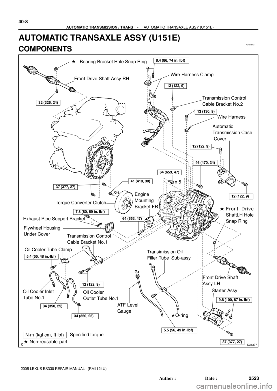
AUTOMATIC TRANSAXLE ASSY (U151E)
COMPONENTS