Page 55 of 969

GLOSSARY OF SAE AND TOYOTA TERMS
This glossary lists all SAE-J1930 t")
0103D-09
- INTRODUCTIONTERMS FOR AUTOMATIC TRANSAXLE REPAIR
MANUAL01-7
7 Author�: Date�:
U151E, U151F A/T REPAIR MANUAL (RM1021U)
GLOSSARY OF SAE AND TOYOTA TERMS
This glossary lists all SAE-J1930 terms and abbreviations used in this manual in compliance with SAE rec-
ommendations, as well as their Toyota equivalents.
SAE
ABBREVIATIONSSAE TERMSTOYOTA TERMS
( )--ABBREVIATIONS
A/CAir ConditioningAir Conditioner
ACLAir CleanerAir Cleaner
AIRSecondary Air InjectionAir Injection (AI)
APAccelerator Pedal-
B+Battery Positive Voltage+B, Battery Voltage
BAROBarometric Pressure-
CACCharge Air CoolerInter cooler
CARBCarburetorCarburetor
CFIContinuous Fuel Injection-
CKPCrankshaft PositionCrank Angle
CLClosed LoopClosed Loop
CMPCamshaft positionCam Angle
CPPClutch Pedal Position-
CTOXContinuous Trap Oxidizer-
CTPClosed Throttle Potion-
DFIDirect Fuel Injection (Diesel)Direct Injection (DI)
DIDistributor Ignition-
DLC1
DLC2
DLC3Data Link Connector 1
Data Link Connector 2
Data Link Connector 31: Check Connector
2: Total Diagnosis Communication Link (TDCL)
3: OBD II Diagnostic Connector
DTCDiagnostic Trouble CodeDiagnostic Code
DTMDiagnostic Test Mode-
ECLEngine Control Level-
ECMEngine Control ModuleEngine ECU (Electronic Control Unit)
ECTEngine Control TemperatureCoolant Temperature, Water Temperature (THW)
EEPROMElectrically Erasable Programmable Read Only
memoryElectrically Erasable Programmable Read Only memory
(EEPROM),
Erasable Programmable Read Only memory (EPROM)
EFEEarly Fuel EvaporationCold Mixture Heater (CMH), Heat Control Valve (HCV)
EGRExhaust Gas RecirculationExhaust Gas Recirculation (EGR)
EIElectronic IgnitionDistributorless Ignition (DI)
EMEngine ModificationEngine Modification (EM)
EPROMErasable Programmable Read Only MemoryProgrammable Read Only Memory (PROM)
EVAPEvaporative EmissionEvaporative Emission Control (EVAP)
FCFan Control-
FEEPROMFlash Electrically Erasable Programmable
Read Only Memory-
FEPROMFlash Erasable Programmable Read Only Memory-
FFFlexible Fuel-
FPFuel PumpFuel Pump
GENGeneratorAlternator
GNDGroundGround (GND)
HO2SHeated Oxygen SensorHeated Oxygen Sensor (HO2S)
IACIdol Air ControlIdol Speed Control (ISC)
IATIntake Air TemperatureIntake or Inlet Air Temperature
ICMIgnition Control Module-
IFIIndirect Fuel InjectionIndirect Injection
IFSInertia Fuel-Shutoff-
Page 380 of 969
14-4
- ENGINE MECHANICALENGINE (3MZ-FE)
2096 Author�: Date�:
2005 LEXUS ES330 REPAIR MANUAL (RM1124U)
(2) See the table below for possible causes, then inspect the applicable causes and repair them if
necessary.
COHCProblemsCauses
NormalHighRough idle
5. Faulty ignitions:
�Incorrect timing
�Fouled, shorted or improperly gapped plugs
6. Incorrect valve clearance
7. Leaks in intake and exhaust valves
8. Leaks in cylinders
LowHighRough idle
(Fluctuating HC reading)
1. Vacuum leaks:
�PCV hoses
�Intake manifold
�Throttle body
�Brake booster line
2. Lean mixture causing misfire
HighHighRough idle
(Black smoke from exhaust)
1. Restricted air filter
2. Plugged PCV valve
3. Faulty SFI systems:
�Faulty pressure regulator
�Defective engine coolant temperature sensor
�Defective mass air flow meter
�Faulty ECM
�Faulty injectors
�Faulty throttle body
Page 490 of 969
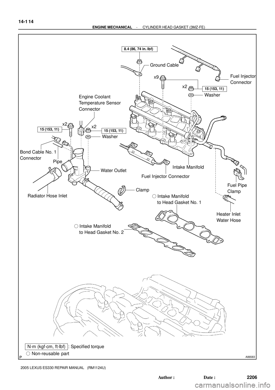
A86583� Non-reusable part
: Specified torqueN´m (kgf´cm, ft´lbf)� Intake Manifold
to Head Gasket No. 2� Intake Manifold
to Head Gasket No. 1
Radiator Hose InletWater Outlet
Heater Inlet
Water Hose Intake Manifold Ground Cable
Washer
8.4 (86, 74 in.Vlbf)
x2x9
x2
Washer
15 (153, 11)
15 (153, 11)
Fuel Pipe
Clamp
15 (153, 11)
Fuel Injector
Connector
Clamp
Fuel Injector Connector
x2
Engine Coolant
Temperature Sensor
Connector
Bond Cable No. 1
Connector
Pipe
14-1 14
- ENGINE MECHANICALCYLINDER HEAD GASKET (3MZ-FE)
2206 Author�: Date�:
2005 LEXUS ES330 REPAIR MANUAL (RM1124U)
Page 503 of 969
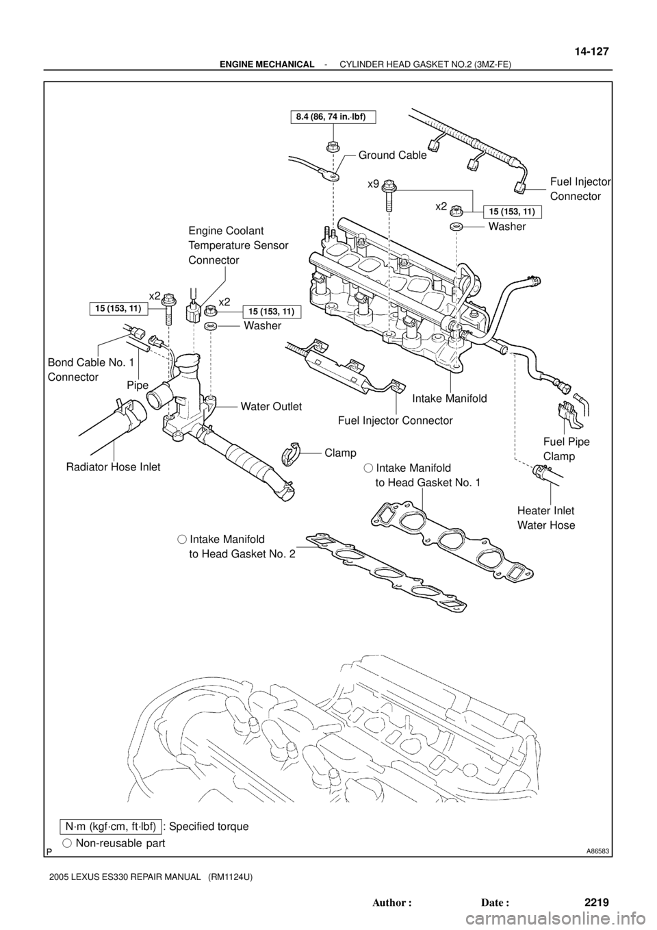
A86583� Non-reusable part
: Specified torqueN´m (kgf´cm, ft´lbf)� Intake Manifold
to Head Gasket No. 2� Intake Manifold
to Head Gasket No. 1
Radiator Hose InletWater Outlet
Heater Inlet
Water Hose Intake Manifold Ground Cable
Washer
8.4 (86, 74 in.Vlbf)
x2x9
x2
Washer
15 (153, 11)
15 (153, 11)
Fuel Pipe
Clamp
15 (153, 11)
Fuel Injector
Connector
Clamp
Fuel Injector Connector
x2
Engine Coolant
Temperature Sensor
Connector
Bond Cable No. 1
Connector
Pipe
- ENGINE MECHANICALCYLINDER HEAD GASKET NO.2 (3MZ-FE)
14-127
2219 Author�: Date�:
2005 LEXUS ES330 REPAIR MANUAL (RM1124U)
Page 560 of 969
 (32) (68)(104)(140)(176)
Temperature �C (�F) 30
0.2 0.515 10 20
Resistance kW
A84678
Ohmmeter
-20 0 20406080
(-4) (32) (68)(104)(140)(176)
Temperature �C (�F) 30
0.")
A84677
Ohmmeter
-20 0 20406080
(-4) (32) (68)(104)(140)(176)
Temperature �C (�F) 30
0.2 0.515 10 20
Resistance kW
A84678
Ohmmeter
-20 0 20406080
(-4) (32) (68)(104)(140)(176)
Temperature �C (�F) 30
0.2 0.515 10 20
Resistance kW
- ENGINE CONTROL SYSTEMSFI SYSTEM (3MZ-FE)
10-3
2008 Author�: Date�:
2005 LEXUS ES330 REPAIR MANUAL (RM1124U)
(b) Inspect the resistance.
(1) Using an ohmmeter, measure the resistance be-
tween the terminals.
Standard:
Tester ConnectionSpecified Condition
4 (THA) - 5 (E2)13.6 to 18.4 kW at -20�C (-4�F)
4 (THA) - 5 (E2)2.21 to 2.69 kW at 20�C (68�F)
4 (THA) - 5 (E2)0.493 to 0.667 kW at 60�C (140�F)
If the resistance is not as specified, replace the mass air flow
sensor.
3. INSPECT ENGINE COOLANT TEMPERATURE
SENSOR
(a) Inspect the resistance.
(1) Using an ohmmeter, measure the resistance be-
tween the terminals.
Standard:
Tester ConnectionSpecified Condition
1 (E2) - 2 (THW)2.32 to 2.59 kW at 20�C (68�F)
1 (E2) - 2 (THW)0.310 to 0.326 kW at 80�C (176�F)
NOTICE:
When checking the engine coolant temperature sensor in
water, be careful not to allow water to intrude into the termi-
nals. Then dry the engine coolant temperature sensor after
checking.
If the resistance is not as specified, replace the engine coolant
temperature sensor.
Page 565 of 969

(b)
Deep Socket
Wrench 19
10-8- ENGINE CONTROL SYSTEMENGINE COOLANT TEMPERATURE
SENSOR (3MZ-FE)
2013 Author�: Date�:
2005 LEXUS ES330 REPAIR MANUAL (RM1124U)
ENGINE COOLANT TEMP")
100J3-02
A86247
(a)
(b)
Deep Socket
Wrench 19
10-8- ENGINE CONTROL SYSTEMENGINE COOLANT TEMPERATURE
SENSOR (3MZ-FE)
2013 Author�: Date�:
2005 LEXUS ES330 REPAIR MANUAL (RM1124U)
ENGINE COOLANT TEMPERATURE SENSOR (3MZ-FE)
REPLACEMENT
1. DISCONNECT ENGINE WIRE NO. 3 (BATTERY NEGATIVE TERMINAL)
2. REMOVE RADIATOR LOWER AIR DEFLECTOR (See page 19-5)
3. DRAIN ENGINE COOLANT (See page 16-9)
4. REMOVE ENGINE COOLANT TEMPERATURE
SENSOR
(a) Disconnect the engine coolant temperature sensor con-
nector.
(b) Using a deep socket wrench 19, remove the engine cool-
ant temperature sensor and gasket.
5. INSTALL ENGINE COOLANT TEMPERATURE SENSOR
(a) Using a deep socket wrench 19, install a new gasket and the engine coolant temperature sensor.
Torque: 20 NVm (200 kgfVcm, 14 ftVlbf)
(b) Connect the engine coolant temperature sensor connector.
6. CONNECT ENGINE WIRE NO. 3 (BATTERY NEGATIVE TERMINAL)
Torque: 5.4 NVm (55 kgfVcm, 48 in.Vlbf)
7. ADD ENGINE COOLANT (See page 16-9)
8. CHECK FOR ENGINE COOLANT LEAKS (See page 16-1)
9. INSTALL RADIATOR LOWER AIR DEFLECTOR
10. SYSTEM INITIALIZATION (See page 19-15)
Page 572 of 969
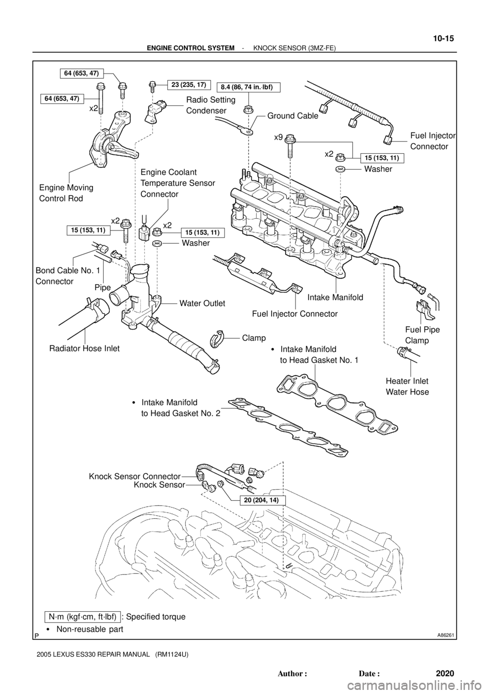
A86261� Non-reusable part
: Specified torqueN´m (kgf´cm, ft´lbf)Knock Sensor
Knock Sensor Connector
20 (204, 14)
� Intake Manifold
to Head Gasket No. 2� Intake Manifold
to Head Gasket No. 1
Radiator Hose InletWater Outlet
Heater Inlet
Water Hose Intake Manifold Ground Cable
Washer
8.4 (86, 74 in.Vlbf)
x2x9
x2
Washer
15 (153, 11)
15 (153, 11)
Fuel Pipe
Clamp
Engine Moving
Control Rod
23 (235, 17)
15 (153, 11)
x2
Fuel Injector
Connector
Clamp
Fuel Injector Connector
64 (653, 47)
x2
Engine Coolant
Temperature Sensor
Connector
Radio Setting
Condenser
64 (653, 47)
Bond Cable No. 1
Connector
Pipe
- ENGINE CONTROL SYSTEMKNOCK SENSOR (3MZ-FE)
10-15
2020 Author�: Date�:
2005 LEXUS ES330 REPAIR MANUAL (RM1124U)
Page 575 of 969

(e)
(f)
(f)
(f)
(f)
(g)
A79749
(a)
(b)
(a)
(b)
A79750
Upper
Engine
Front0 to 5� 10-18
- ENGINE CONTROL SYSTEMKNOCK SENSOR (3MZ-FE)
2023 Author�: Date�:
2005 LEXUS ES330 REPAIR MANUAL (RM")
A86268
(d)
(e)
(f)
(f)
(f)
(f)
(g)
A79749
(a)
(b)
(a)
(b)
A79750
Upper
Engine
Front0 to 5� 10-18
- ENGINE CONTROL SYSTEMKNOCK SENSOR (3MZ-FE)
2023 Author�: Date�:
2005 LEXUS ES330 REPAIR MANUAL (RM1124U)
(d) Disconnect the engine coolant temperature sensor con-
nector.
(e) Remove the clamp.
(f) Remove the 2 bolts, 2 nuts and 2 washers.
(g) Lock the hose clamp as shown in the illustration. Then re-
move the water outlet together with water by-pass hose
No. 1.
(h) Remove the 2 gaskets from the 2 cylinder heads.
12. REMOVE KNOCK SENSOR
(a) Disconnect the 2 knock sensor connectors.
(b) Remove the 2 nuts, then remove the 2 knock sensors.
13. INSTALL KNOCK SENSOR
(a) Install the 2 knock sensors with the 2 nuts as shown in the
illustration.
Torque: 20 NVm (204 kgfVcm, 14 ftVlbf)
(b) Connect the 2 knock sensor connectors.
14. INSTALL WATER OUTLET
(a) Install 2 new gaskets to the 2 cylinder heads.
(b) Install the water outlet together with water by-pass hose No. 1, then unlock the hose clamp.
(c) Tighten the 2 bolts, 2 nuts and 2 washers.
Torque: 15 NVm (153 kgfVcm, 11 ftVlbf)
(d) Install the clamp.
(e) Connect the engine coolant temperature sensor connector.
(f) Connect the bond cable No. 3 connector.
(g) Connect the pipe of the radiator reserve tank.
(h) Connect the radiator hose inlet, then unlock the hose clamp.