Page 446 of 969

2162 Author�: Date�:
2005 LEXUS ES330 REPAIR MANUAL (RM1124U)
92. INSTALL ENGINE MOUNTING BRACKET RH
Torque: 28 NVm (286 kgfVc")
A78753
SST
A52345
14-70
- ENGINE MECHANICALPARTIAL ENGINE ASSY (3MZ-FE)
2162 Author�: Date�:
2005 LEXUS ES330 REPAIR MANUAL (RM1124U)
92. INSTALL ENGINE MOUNTING BRACKET RH
Torque: 28 NVm (286 kgfVcm, 21 ftVlbf)
93. INSTALL TIMING BELT NO.2 COVER
(a) Visually check for cracks and breaks on the gasket of the timing belt cover.
If there is a trace of water intrusion when checking visually, replace the timing belt cover.
(b) Install the timing belt cover.
Torque: 8.5 NVm (87 kgfVcm, 75 in.Vlbf)
94. INSTALL TIMING BELT NO.1 COVER
(a) Visually check for cracks and breaks on the gasket of the timing belt cover.
If there is a trace of water intrusion when checking visually, replace the timing belt cover.
(b) Install the timing belt cover.
Torque: 8.5 NVm (87 kgfVcm, 75 in.Vlbf)
95. INSTALL CRANKSHAFT PULLEY
(a) Align the keyway of the pulley with the key located on the
crankshaft, then slide the pulley into place.
(b) Using SST, install the pulley bolt.
SST 09213-54015 (91651-60855), 09330-00021
Torque: 220 NVm (2,250 kgfVcm, 162 ftVlbf)
96. INSTALL VVT SENSOR
Torque: 8.0 NVm (82 kgfVcm, 71 in.Vlbf)
97. INSTALL CAMSHAFT TIMING OIL CONTROL VALVE ASSY
Torque: 8.0 NVm (82 kgfVcm, 71 in.Vlbf)
98. INSTALL ENGINE HANGER NO.2
Torque: 20 NVm (199 kgfVcm, 14 ftVlbf)
99. INSPECT VALVE CLEARANCE
(a) Turn the crankshaft pulley, then align the timing notch with
the timing mark º0º of the timing belt No. 1 cover.
(b) Check that the valve lifters on the intake side of the No.
1 cylinder are not pushed by the cam.
If the valve lifters are pushed, turn the crankshaft 1 revolution
(360�) and align the marks as above.
Page 461 of 969

14-85
2177 Author�: Date�:
2005 LEXUS ES330 REPAIR MANUAL (RM1124U)
18. INSTALL ENGINE MOUNTING BRACKET RH
(a) Install the engine mou")
P18814
A78760
SST
A52344
- ENGINE MECHANICALTIMING BELT (3MZ-FE)
14-85
2177 Author�: Date�:
2005 LEXUS ES330 REPAIR MANUAL (RM1124U)
18. INSTALL ENGINE MOUNTING BRACKET RH
(a) Install the engine mounting bracket RH with the 2 bolts
and nut.
Torque: 28 NVm (286 kgfVcm, 21 ftVlbf)
19. INSTALL TIMING BELT NO.2 COVER
(a) Visually check for cracks and breaks on the gasket of the timing belt cover.
If there is a trace of water intrusion when checking visually, replace the timing belt cover.
(b) Install the timing belt cover.
Torque: 8.5 NVm (87 kgfVcm, 75 in.Vlbf)
20. INSTALL TIMING BELT NO.1 COVER
(a) Visually check for cracks and breaks on the gasket of the timing belt cover.
If there is a trace of water intrusion when checking visually, replace the timing belt cover.
(b) Install the timing belt cover.
Torque: 8.5 NVm (87 kgfVcm, 75 in.Vlbf)
(c) Install the 2 engine wire protector clamps to the timing belt No. 3 cover.
21. INSTALL CRANKSHAFT PULLEY
(a) Align the keyway of the pulley with the key located on the
crankshaft, then slide the pulley into place.
(b) Using SST, install the pulley bolt.
SST 09213-54015 (91651-60855), 09330-00021
Torque: 220 NVm (2250 kgfVcm, 162 ftVlbf)
22. INSTALL GENERATOR BRACKET NO.2
Torque: 28 NVm (286 kgfVcm, 21 ftVlbf)
23. INSTALL ENGINE MOUNTING STAY NO.2 RH
(a) Install the engine mounting stay No. 2 and engine mount-
ing bracket No. 2 with the bolt.
Torque: 64 NVm (653 kgfVcm, 47 ftVlbf)
Page 515 of 969

14-139
2231 Author�: Date�:
2005 LEXUS ES330 REPAIR MANUAL (RM1124U)
16. INSTALL OIL PUMP SEAL
(a) Apply multi-purpose greas")
A78766
SST
A78746
Inward
Sensor
- ENGINE MECHANICALOIL PUMP SEAL (3MZ-FE)
14-139
2231 Author�: Date�:
2005 LEXUS ES330 REPAIR MANUAL (RM1124U)
16. INSTALL OIL PUMP SEAL
(a) Apply multi-purpose grease to a new oil seal lip.
NOTICE:
Keep the lip free of foreign objects.
(b) Using SST and a hammer, tap in the new oil seal until its
surface is flush with the oil pump edge.
SST 09223-00010
NOTICE:
�Be careful not to tap the oil seal at an angle.
�Wipe off extra grease on the crankshaft.
17. INSTALL CRANKSHAFT TIMING PULLEY
(a) Align the keyway of the pulley with the key located on the
crankshaft, then slide the pulley into place.
NOTICE:
Do not scratch the sensor area of the crankshaft timing
pulley.
(b) Install the timing belt plate with the bolt.
Torque: 8.0 NVm (82 kgfVcm, 71 in.Vlbf)
18. INSPECT TIMING BELT (See page 14-79)
19. INSTALL TIMING BELT (See page 14-79)
SST 09960-10010 (09962-01000, 09963-01000)
20. INSTALL TIMING BELT TENSIONER ASSY (See page 14-79)
21. INSTALL TIMING BELT GUIDE NO.2 (See page 14-79)
22. INSTALL ENGINE MOUNTING BRACKET RH (See page 14-79)
23. INSTALL TIMING BELT NO.2 COVER (See page 14-79)
24. INSTALL TIMING BELT NO.1 COVER (See page 14-79)
25. INSTALL CRANKSHAFT PULLEY (See page 14-79)
SST 09213-54015 (91651-60855), 09330-00021
26. INSTALL GENERATOR BRACKET NO.2 (See page 14-79)
27. INSTALL ENGINE MOUNTING STAY NO.2 RH (See page 14-79)
28. INSTALL ENGINE MOVING CONTROL ROD (See page 14-79)
29. INSTALL VANE PUMP V BELT (See page 14-5)
30. INSTALL V (COOLER COMPRESSOR TO CRANKSHAFT PULLEY) BELT NO.1
(See page 14-5)
31. INSPECT DRIVE BELT DEFLECTION AND TENSION (See page 14-1)
32. INSTALL FRONT WHEEL RH (See page 14-5)
33. CHECK FOR ENGINE OIL LEAKS
Page 544 of 969
 14-168
- ENGINE MECHANICALCYLINDER BLOCK ASSY (3MZ-FE)
2260 Author�: Date�:
2005 LEXUS ES330 REPAIR MANUAL (")
P12599
A78807
Mark
1, 2, 3 or 4
A78808
Plastigage
A10530
A78809Less than 6 mm (0.23 in.) 14-168
- ENGINE MECHANICALCYLINDER BLOCK ASSY (3MZ-FE)
2260 Author�: Date�:
2005 LEXUS ES330 REPAIR MANUAL (RM1124U)
(b) Align the key of the bearing with the keyway of the cylinder
block, then push in the 4 upper bearings.
NOTICE:
Do not apply engine oil to the bearing and its contact sur-
face.
(c) Align the key of the bearing with the keyway of the bearing
cap, then push in the 4 lower bearings.
NOTICE:
Do not apply engine oil to the bearing and its contact sur-
face.
HINT:
A number is marked on each bearing cap to indicate the instal-
lation position.
(d) Place the crankshaft on the cylinder block.
(e) Lay a strip of Plastigage across each journal.
(f) Examine the front marks and numbers, then install the
bearing caps on the cylinder block.
(g) Apply a light coat of engine oil to the threads of the bear-
ing cap bolts.
(h) Temporarily install the 8 bearing cap bolts to the inside
positions.
(i) Install the bearing cap by hand using the inner bolt as a
guide. Stop when the bearing cap is about 6 mm (0.23 in.)
away from contact with the cylinder block.
Page 552 of 969
No.")
P12418A32958
A78320
No. 1:
No. 2:2A
A86598
Lower Side
Rail
No. 2
Compression Expander No. 1
Compression
Front Mark
Upper Side
Rail
P12402
A78806
No. 1 and No. 4:
Upper
Lower
22.4 mm (0.882 in.)No. 2 and No. 3:
19.0 mm (0.748 in.) 14-176
- ENGINE MECHANICALCYLINDER BLOCK ASSY (3MZ-FE)
2268 Author�: Date�:
2005 LEXUS ES330 REPAIR MANUAL (RM1124U)
36. INSTALL PISTON PIN HOLE SNAP RING
(a) Using a small screwdriver, install a new snap ring on the
other end of the piston pin hole.
HINT:
Be sure that the end of gap of the snap ring is not aligned with
the pin hole cutout of the piston.
37. INSTALL PISTON RING SET
(a) Install the expander and 2 side rails by hand.
(b) Using a piston ring expander, install the 2 compression
rings.
HINT:
The No. 2 compression ring is installed with the code mark º2Aº
facing upward as shown in the illustration.
(c) Position the piston rings so that the ring ends are ar-
ranged as shown in the illustration.
NOTICE:
Do not align the ring ends.
38. INSTALL CONNECTING ROD BEARING
(a) Align the key of the bearing with the keyway of the con-
necting rod or cap.
NOTICE:
Clean the backside of the bearing and bearing surface of
the connecting rod. The surface should be free of dust and
oils.
39. INSTALL CRANKSHAFT BEARING
HINT:
Crankshaft bearings come in widths of 22.4 mm (0.882 in.) and
19.0 mm (0.748 in.). Install the 22.4 mm (0.882 in.) bearings in
the No. 1 and No. 4 cylinder block journal positions with the
main bearing caps. Install the 19.0 mm (0.748 in.) bearings in
the No. 2 and No. 3 positions.
(a) Clean each main journal and the bearing.
Page 553 of 969

14-177
2269 Author�: Date�:
2005 LEXUS ES330 REPAIR MANUAL (RM1124U)
(b) Align the key of the be")
P12599
A78807
Mark
1, 2, 3 or 4
P12600
A05264
A10530
- ENGINE MECHANICALCYLINDER BLOCK ASSY (3MZ-FE)
14-177
2269 Author�: Date�:
2005 LEXUS ES330 REPAIR MANUAL (RM1124U)
(b) Align the key of the bearing with the keyway of the cylinder
block, then push in the 4 upper bearings.
NOTICE:
Do not apply engine oil to the bearing and its contact sur-
face.
(c) Align the key of the bearing with the keyway of the bearing
cap, then push in the 4 lower bearings.
NOTICE:
Do not apply engine oil to the bearing and its contact sur-
face.
HINT:
A number is marked on each bearing cap to indicate the instal-
lation position.
40. INSTALL CRANKSHAFT THRUST WASHER SET
(a) Install the 2 thrust washers under the No. 2 journal posi-
tion of the cylinder block with the oil grooves facing out-
ward.
(b) Install the 2 thrust washers on the No. 2 bearing cap with
the grooves facing outward.
41. INSTALL CRANKSHAFT
(a) Apply engine oil to the upper bearing, then install the
crankshaft on the cylinder block.
(b) Examine the front marks and numbers, then install the
bearing caps on the cylinder block.
(c) Apply a light coat of engine oil to the threads of the bear-
ing cap bolts.
Page 649 of 969
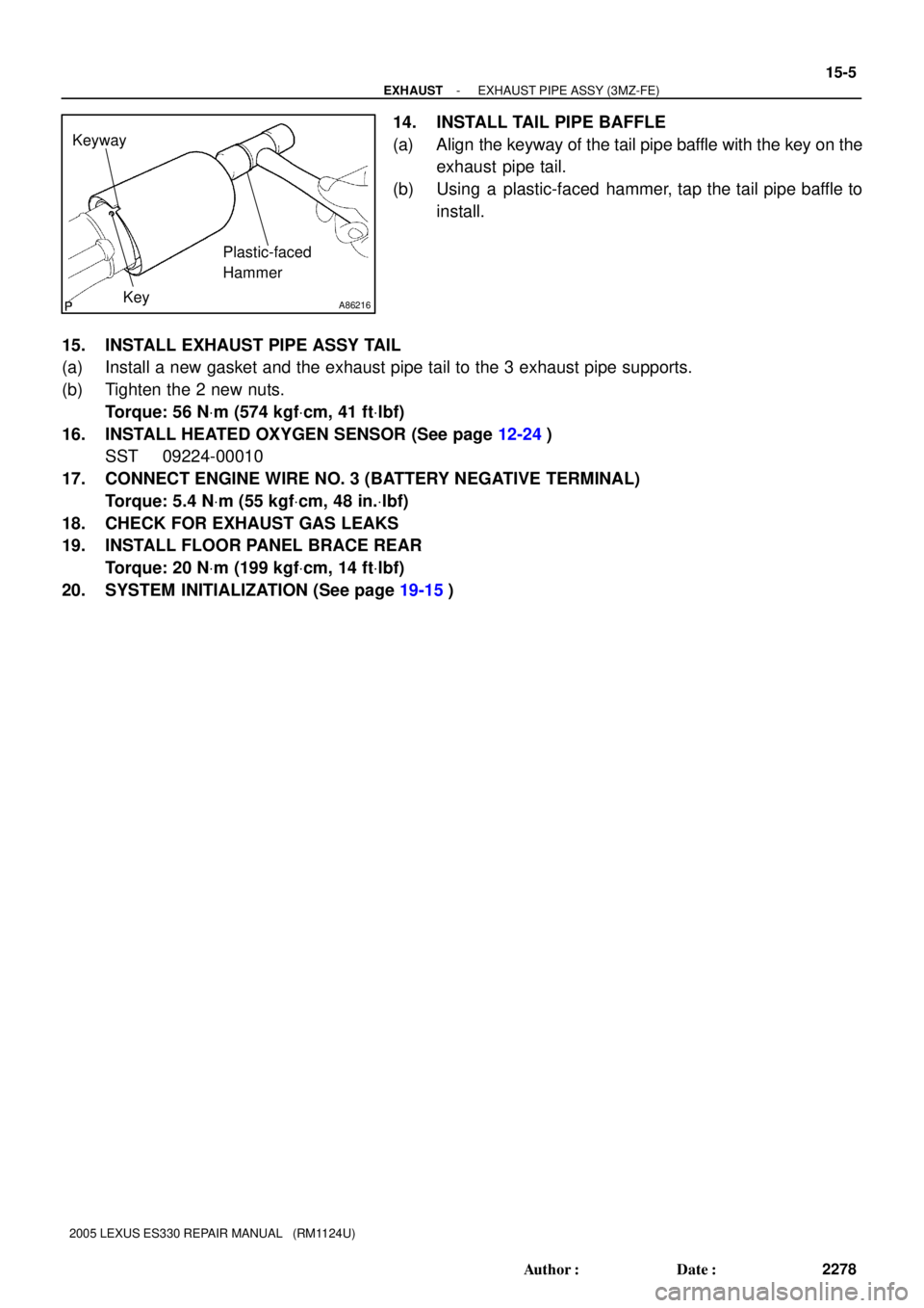
A86216
Keyway
KeyPlastic-faced
Hammer
- EXHAUSTEXHAUST PIPE ASSY (3MZ-FE)
15-5
2278 Author�: Date�:
2005 LEXUS ES330 REPAIR MANUAL (RM1124U)
14. INSTALL TAIL PIPE BAFFLE
(a) Align the keyway of the tail pipe baffle with the key on the
exhaust pipe tail.
(b) Using a plastic-faced hammer, tap the tail pipe baffle to
install.
15. INSTALL EXHAUST PIPE ASSY TAIL
(a) Install a new gasket and the exhaust pipe tail to the 3 exhaust pipe supports.
(b) Tighten the 2 new nuts.
Torque: 56 NVm (574 kgfVcm, 41 ftVlbf)
16. INSTALL HEATED OXYGEN SENSOR (See page 12-24)
SST 09224-00010
17. CONNECT ENGINE WIRE NO. 3 (BATTERY NEGATIVE TERMINAL)
Torque: 5.4 NVm (55 kgfVcm, 48 in.Vlbf)
18. CHECK FOR EXHAUST GAS LEAKS
19. INSTALL FLOOR PANEL BRACE REAR
Torque: 20 NVm (199 kgfVcm, 14 ftVlbf)
20. SYSTEM INITIALIZATION (See page 19-15)
Page 689 of 969
A36784
A78725
Seal Packing
Seal Width
2 to 3 mm
(0.08 to 0.12 in.) A
A
BB
C
C
A36785
- LUBRICATIONOIL PUMP ASSY (3MZ-FE)
17-13
2318 Author�: Date�:
41. INSTALL OIL PUMP ASSY
(a) Remove any old seal packing material from the contact
surface.
(b) Apply a light coat of engine oil to a new O-ring, then place
it on the cylinder block.
(c) Apply a continuous bead of seal packing (Diameter 2 to
3 mm (0.08 to 0.12 in.)) as shown in the illustration.
Seal packing: Part No. 08826-00080 or equivalent
NOTICE:
�Remove any oil from contact surface.
�Apply seal packing to the inner side of the bolt holes.
�Install the oil pump within 3 minutes after applying
seal packing.
�Do not expose the seal packing to engine oil within 2
hours after installing.
(d) Align the key of the oil pump drive gear with the keyway
located on the crankshaft, then slide the oil pump into
place.