Page 230 of 969

SHIFT LOCK SYSTEM
ON-VEHICLE INSPECTION
1. CHECK SHIFT")
40067-09
C63995IG
E STP
- AUTOMATIC TRANSMISSION / TRANSSHIFT LOCK SYSTEM
40-31
2546 Author�: Date�:
2005 LEXUS ES330 REPAIR MANUAL (RM1124U)
SHIFT LOCK SYSTEM
ON-VEHICLE INSPECTION
1. CHECK SHIFT LOCK OPERATION
(a) Shift the shift lever to P position.
(b) Turn the ignition switch to LOCK.
(c) Check that the shift lever cannot be shifted to any other positions other than P.
(d) Turn the ignition switch to ON, depress the brake pedal and check that the shift lever can be shifted
to any other positions.
2. CHECK SHIFT LOCK RELEASE BUTTON OPERATION
(a) Using a small screwdriver, remove the shift lock release cover.
(b) When operating the shift lever with the shift lock release button pressed, check that the lever can be
shifted to any position other than P.
3. CHECK KEY INTERLOCK OPERATION
(a) Turn the ignition switch to ON.
(b) Depress the brake pedal and shift the shift lever to any other position other than P.
(c) Check that the ignition key cannot be turned to LOCK.
(d) Shift the shift lever to P position, turn the ignition key to LOCK and check that the ignition key can be
removed.
4. INSPECT SHIFT LOCK CONTROL UNIT ASSEMBLY
(a) Using a voltmeter, measure the voltage at each terminal.
HINT:
Do not disconnect the shift lock control unit assembly connec-
tor.
TerminalMeasuring ConditionVoltage (V)
3 (STP) - 1 (E)Depress brake pedal10 - 14
3 (STP) - 1 (E)Release brake pedal0
5 (IG) - (E)Ignition switch ON10 - 14
5 (IG) - (E)Ignition switch OFF0
Page 238 of 969
C93323
Lock Key
C92370
C93015
C93325
- AUTOMATIC TRANSMISSION / TRANSFLOOR SHIFT ASSY
40-39
2554 Author�: Date�:
2005 LEXUS ES330 REPAIR MANUAL (RM1124U)
40. INSTALL FLOOR SHIFT PARKING LOCK CABLE
ASSY
(a) Using a screwdriver, unlock the claw of the lock key of au-
tomatic adjustment part.
(b) Insert the slide cap into the through hole and install.
(c) Shift the shift lever to P position and turn the ignition
switch to Lock.
(d) Insert the lever pin into the hole of the parking lock cable.
(e) Lock the lock key.
41. INSTALL BATTERY
42. ADJUST SHIFT LEVER POSITION(SEE PAGE 40-40)
43. INSPECT SHIFT LEVER POSITION(SEE PAGE 40-40)
44. INSPECT CHECK KEY INTERLOCK OPERATION(SEE PAGE 40-31)
45. INSPECT CHECK SHIFT LOCK OPERATION(SEE PAGE 40-31)
46. INSPECT CHECK SHIFT LOCK RELEASE BUTTON OPERATION(SEE PAGE 40-31)
47. INSTALL CONSOLE BOX DUCT NO.1(SEE PAGE 55-17)
48. INSTALL AIR DUCT REAR NO.2(SEE PAGE 55-17)
49. INSTALL AIR DUCT REAR NO.1(SEE PAGE 55-17)
Page 241 of 969
C93152
C93323
Lock Key
C92370
C93015
C93325
40-42
- AUTOMATIC TRANSMISSION / TRANSFLOOR SHIFT PARKING LOCK CABLE ASSY
2557 Author�: Date�:
2005 LEXUS ES330 REPAIR MANUAL (RM1124U)
16. INSTALL FLOOR SHIFT PARKING LOCK CABLE
ASSY
(a) Turn the ignition switch to ACC or ON.
(b) Connect the cable to the upper bracket.
(c) Connect the cable clamp.
(d) Shift the shift lever to P range and turn the ignition switch
to LOCK.
(e) Using a screwdriver, unlock the claw of the lock key of au-
tomatic adjustment part.
(f) Insert the slide cap into the through hole and install.
(g) Insert the lever pin into the hole of the parking lock cable.
(h) Lock the lock key.
Page 242 of 969
- AUTOMATIC TRANSMISSION / TRANSFLOOR SHIFT PARKING LOCK CABLE ASSY
40-43
2558 Author�: Date�:
2005 LEXUS ES330 REPAIR MANUAL (RM1124U)
17. INSPECT CHECK KEY INTERLOCK OPERATION(See page 40-31)
18. INSTALL CONSOLE BOX DUCT NO.1
19. INSTALL AIR DUCT REAR NO.2
20. INSTALL AIR DUCT REAR NO.1
21. INSTALL INSTRUMENT PANEL FINISH PANEL END RH
22. INSTALL INSTRUMENT PANEL FINISH PANEL END LH
23. INSTALL CONSOLE BOX ASSY
24. INSTALL CONSOLE BOX CARPET
25. INSTALL CONSOLE PANEL UPPER REAR
26. INSTALL INSTRUMENT PANEL INSERT SUB-ASSY LOWER LH
27. INSTALL INSTRUMENT PANEL SUB-ASSY UPPER
28. INSTALL INSTRUMENT PANEL SUB-ASSY LOWER
29. INSTALL INSTRUMENT PANEL UNDER COVER SUB-ASSY NO.1
30. INSTALL FRONT DOOR SCUFF PLATE RH
31. INSTALL FRONT DOOR SCUFF PLATE LH
Page 265 of 969

2454 Author�: Date�:
2005 LEXUS ES330 REPAIR MANUAL (RM1124U)
34. INSTALL BRAKE PEDAL RETURN SPRING
35. INSTALL DRIVER SI")
F16914
F16911
32-20- BRAKEACCELERATOR & BRAKE PEDAL ASSY (From August,
2002)
2454 Author�: Date�:
2005 LEXUS ES330 REPAIR MANUAL (RM1124U)
34. INSTALL BRAKE PEDAL RETURN SPRING
35. INSTALL DRIVER SIDE JUNCTION BLOCK ASSY
(a) Install the junction block assy with the 3 nuts, then con-
nect the each connector.
36. INSTALL STEERING COLUMN ASSY (SEE PAGE 50-8)
37. CONNECT STEERING SLIDING YOKE SUB-ASSY (SEE PAGE 50-8)
38. CONNECT FLOOR SHIFT PARKING LOCK CABLE ASSY (SEE PAGE 50-8)
39. INSPECT CHECK KEY INTERLOCK OPERATION (SEE PAGE 50-8)
40. INSTALL TURN SIGNAL SWITCH ASSY (SEE PAGE 50-8)
41. INSPECT SPIRAL CABLE SUB-ASSY (SEE PAGE 60-31)
42. INSTALL STEERING COLUMN COVER (SEE PAGE 50-8)
43. INSTALL STEERING COLUMN COVER LWR NO.2 (SEE PAGE 50-8)
44. INSTALL HEATER TO FOOT DUCT NO.3 (SEE PAGE 32-14)
45. INSTALL INSTRUMENT PANEL INSERT SUB-ASSY LOWER LH (SEE PAGE 71-1 1)
46. INSTALL INSTRUMENT PANEL SUB-ASSY UPPER (SEE PAGE 71-1 1)
47. INSTALL FRONT DOOR SCUFF PLATE LH (SEE PAGE 71-1 1)
48. PLACE FRONT WHEELS FACING STRAIGHT AHEAD
49. INSTALL STEERING WHEEL ASSY (SEE PAGE 50-8)
50. INSPECT HORN BUTTON ASSY (SEE PAGE 60-22)
51. INSTALL HORN BUTTON ASSY (SEE PAGE 60-22)
52. INSTALL STEERING PAD SWITCH (SEE PAGE 82-1)
53. INSTALL CONNECTOR COVER (SEE PAGE 82-1)
54. INSTALL STEERING WHEEL COVER LOWER NO.2
55. INSPECT SRS WARNING LIGHT (SEE PAGE 05-818)
Page 304 of 969
320E4-03
F45687
F45687
- BRAKEYAWRATE SENSOR (From July, 2003)
32-59
2493 Author�: Date�:
2005 LEXUS ES330 REPAIR MANUAL (RM1124U)
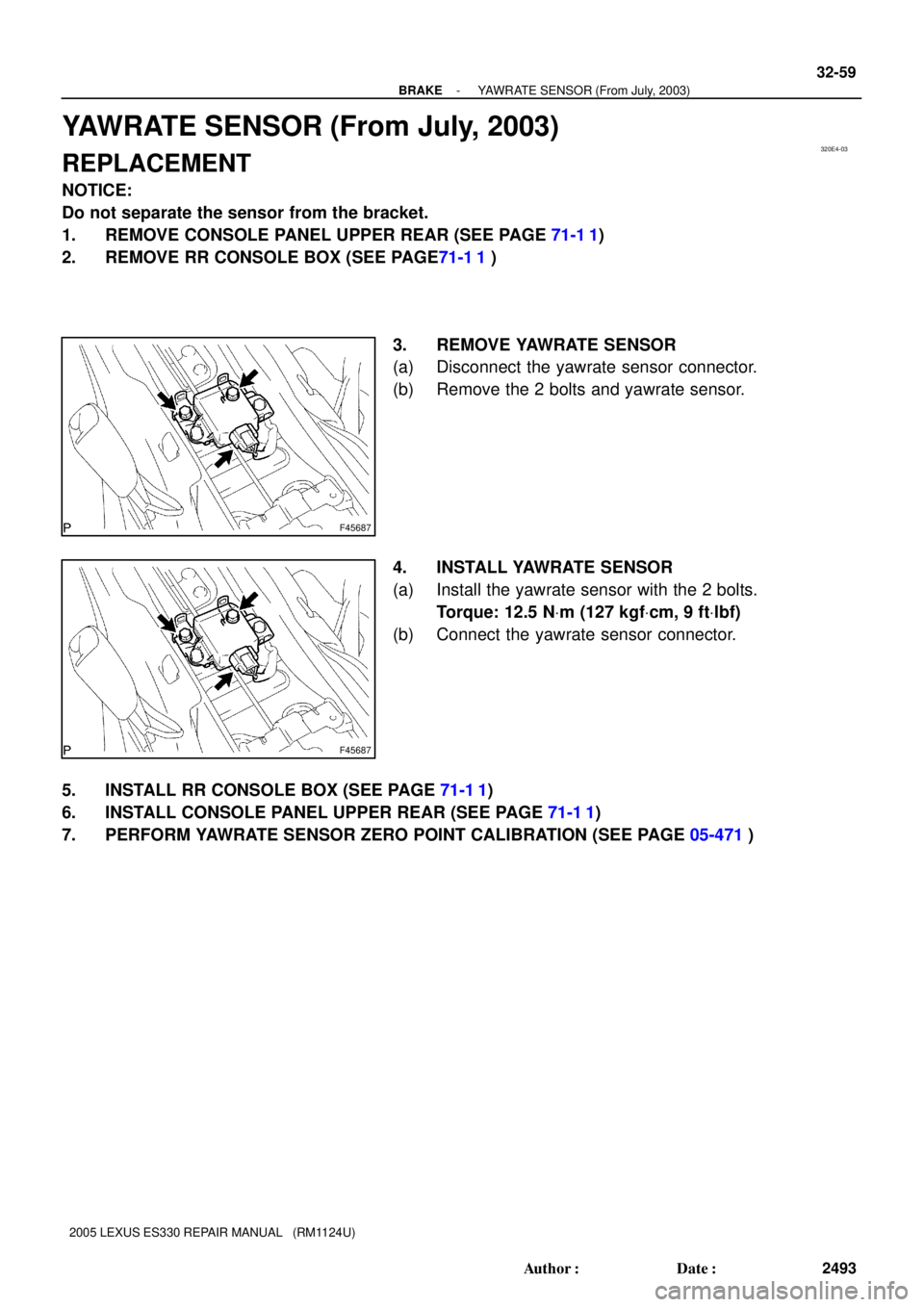
YAWRATE SENSOR (From July, 2003)
REPLACEMENT
NOTICE:
Do not separate the sensor from the bracket.
1. REMOVE CONSOLE PANEL UPPER REAR (SEE PAGE 71-1 1)
2. REMOVE RR CONSOLE BOX (SEE PAGE71-1 1 )
3. REMOVE YAWRATE SENSOR
(a) Disconnect the yawrate sensor connector.
(b) Remove the 2 bolts and yawrate sensor.
4. INSTALL YAWRATE SENSOR
(a) Install the yawrate sensor with the 2 bolts.
Torque: 12.5 NVm (127 kgfVcm, 9 ftVlbf)
(b) Connect the yawrate sensor connector.
5. INSTALL RR CONSOLE BOX (SEE PAGE 71-1 1)
6. INSTALL CONSOLE PANEL UPPER REAR (SEE PAGE 71-1 1)
7. PERFORM YAWRATE SENSOR ZERO POINT CALIBRATION (SEE PAGE 05-471)
Page 430 of 969
A36784
A78725
Seal Packing
Seal Width
2 to 3 mm
(0.08 to 0.12 in.) A
A
BB
C
C
A36785
14-54
- ENGINE MECHANICALPARTIAL ENGINE ASSY (3MZ-FE)
2146 Author�: Date�:
2005 LEXUS ES330 REPAIR MANUAL (RM1124U)
60. INSTALL OIL PUMP ASSY
(a) Remove any old packing material from the contact sur-
face.
(b) Apply a light coat of engine oil to a new O-ring, then place
it on the cylinder block.
(c) Apply a continuous bead of seal packing (Diameter 2 to
3 mm (0.08 to 0.12 in.)) as shown in the illustration.
Seal packing: Part No. 08826-00080 or equivalent
NOTICE:
�Remove any oil from contact surface.
�Apply seal packing to the inner side of the bolt holes.
�Install the oil pump within 3 minutes after applying
seal packing.
�Do not expose the seal packing to engine oil within 2
hours after installing.
(d) Align the key of the oil pump drive gear with the keyway
located on the crankshaft, then slide the oil pump into
place.
Page 440 of 969

2156 Author�: Date�:
2005 LEXUS ES330 REPAIR MANUAL (RM1124U)
79. INSTALL NO")
A78744
Align
A05214
A78745
10
1
2
3
45
6
7
8
9
A78746
Inward
Sensor 14-64
- ENGINE MECHANICALPARTIAL ENGINE ASSY (3MZ-FE)
2156 Author�: Date�:
2005 LEXUS ES330 REPAIR MANUAL (RM1124U)
79. INSTALL NO.3 CAMSHAFT SUB-ASSY
NOTICE:
Since the thrust clearance of the camshaft is small, the
camshaft must be kept level while being installed. If the
camshaft is not kept level, the cylinder head or camshaft
may be damaged. To avoid this, the following steps must
be carried out.
(a) Apply new engine oil to the thrust portion and journal of
the camshaft.
(b) Align the timing marks (1 dot marks) of the camshaft drive
and driven gears.
(c) Place the camshaft on the cylinder head.
(d) Install the 5 bearing caps in their proper locations.
(e) Apply a light coat of engine oil to the threads of the bear-
ing cap bolts.
(f) Using several steps, tighten the 10 bearing cap bolts uni-
formly in the sequence shown in the illustration.
Torque: 16 NVm (163 kgfVcm, 12 ftVlbf)
(g) Remove the service bolt.
80. INSTALL CRANKSHAFT TIMING PULLEY
(a) Align the keyway of the timing pulley with the key located
on the crankshaft, then slide the timing pulley into place.
NOTICE:
Do not scratch the sensor area of the crankshaft timing
pulley.
(b) Install the timing belt plate with the bolt.
Torque: 8.0 NVm (82 kgfVcm, 71 in.Vlbf)