Page 290 of 969

F41559
F41865
Anti Squeal
Shim No.2 Anti Squeal
Shim No.2
Anti Squeal
Shim No.1
Anti Squeal
Shim No.1
Wear Indicator
- BRAKEREAR BRAKE
32-45
2479 Author�: Date�:
2005 LEXUS ES330 REPAIR MANUAL (RM1124U)
32. INSTALL PISTON SEAL
(a) Apply the lithium soap base glycol grease to a new piston seal.
(b) Install the piston seal to the disc brake cylinder.
33. INSTALL REAR DISC BRAKE PISTON
(a) Apply the lithium soap base glycol grease to the piston.
(b) Install the piston to the disc brake cylinder.
NOTICE:
Do not screw the piston forcibly into the disc brake cylinder.
34. INSTALL CYLINDER BOOT
(a) Apply the lithium soap base glycol grease to a new cylin-
der boot.
(b) Install the cylinder boot to the disc brake cylinder.
HINT:
Install the boot securely to the grooves of the cylinder and pis-
ton.
(c) Using a screwdriver, install a new set ring.
NOTICE:
Do not damage the cylinder boot.
35. INSTALL REAR DISC BRAKE CYLINDER MOUNTING LH
(a) Install the disc brake cylinder mounting with the 2 bolts.
Torque: 61.8 NVm (630 kgfVcm, 46 ftVlbf)
36. INSTALL REAR DISC BRAKE PAD SUPPORT PLATE
(a) Install the bottom side rear disc brake pad support plate.
37. INSTALL REAR DISC BRAKE PAD SUPPORT PLATE
(a) Install the upper side rear disc brake pad support plate.
38. INSTALL REAR DISC BRAKE ANTI SQUEAL SHIM KIT
(a) Apply the both sides of anti squeal shim No.1 with pad
grease, and install the shim together with anti squeal shim
No.2 to each pad.
(b) Install the wear indicator to the 2 brake pads.
NOTICE:
�When replacing worn pads, the anti squeal shims
must be replaced together with the pads.
�Install the shims and pad wear indicator correctly of
which positions and directions.
39. INSTALL DISC BRAKE PAD KIT REAR (PAD ONLY)
(a) Install the 2 disc brake pads with the pad wear indicator facing downward.
NOTICE:
There should be no oil or grease on the friction surface of the pads and the disc.
Page 291 of 969

F41551
F41562
Cylinder Slide Pin
Cylinder Mounting
Lithium soap base glycol grease
F41558Lithium soap base glycol grease
32-46
- BRAKEREAR BRAKE
2480 Author�: Date�:
2005 LEXUS ES330 REPAIR MANUAL (RM1124U)
40. INSTALL REAR DISC BRAKE CYLINDER SLIDE PIN
(a) Using a hexagon wrench (8 mm), install the cylinder slide
pin.
Torque: 39.2 NVm (400 kgfVcm, 29 ftVlbf)
41. INSTALL REAR DISC BRAKE BUSH DUST BOOT
(a) Apply the lithium soap base glycol grease to seal surface
of a new bush dust boot.
(b) Install the bush dust boot to the cylinder slide pin.
42. INSTALL REAR DISC BRAKE CYLINDER SLIDE BUSH
(a) Apply the lithium soap base glycol grease to a new cylin-
der slide bush.
(b) Install the cylinder slide bush to the disc brake cylinder.
43. INSTALL DISC BRAKE CYLINDER ASSY REAR LH
(a) Apply the lithium soap base glycol grease to the cylinder slide pin.
(b) Install the disc brake cylinder to the cylinder slide pin.
44. INSTALL REAR DISC BRAKE CYLINDER SLIDE PIN
(a) Apply the lithium soap base glycol grease to the cylinder slide pin.
(b) Install the cylinder slide pin to the disc brake cylinder.
Torque: 34.3 NVm (350 kgfVcm, 25 ftVlbf)
45. CONNECT REAR LH FLEXIBLE HOSE
(a) Connect a new gasket and flexible hose with the union bolt.
Torque: 29.4 NVm (300 kgfVcm, 22 ftVlbf)
HINT:
Install the flexible hose lock securely in the lock hole of the disc brake cylinder.
46. FILL RESERVOIR WITH BRAKE FLUID
47. BLEED MASTER CYLINDER (SEE PAGE 32-4)
SST 09023-00101
48. BLEED BRAKE LINE (SEE PAGE 32-4)
49. CHECK FLUID LEVEL IN RESERVOIR (SEE PAGE 32-4)
50. CHECK BRAKE FLUID LEAKAGE
51. INSTALL REAR WHEEL
Torque: 103 NVm (1050 kgfVcm, 76 ftVlbf)
Page 293 of 969

2482 Author�: Date�:
2005 LEXUS ES330 REPAIR MANUAL (RM1124")
320E2-04
F40998
C84798
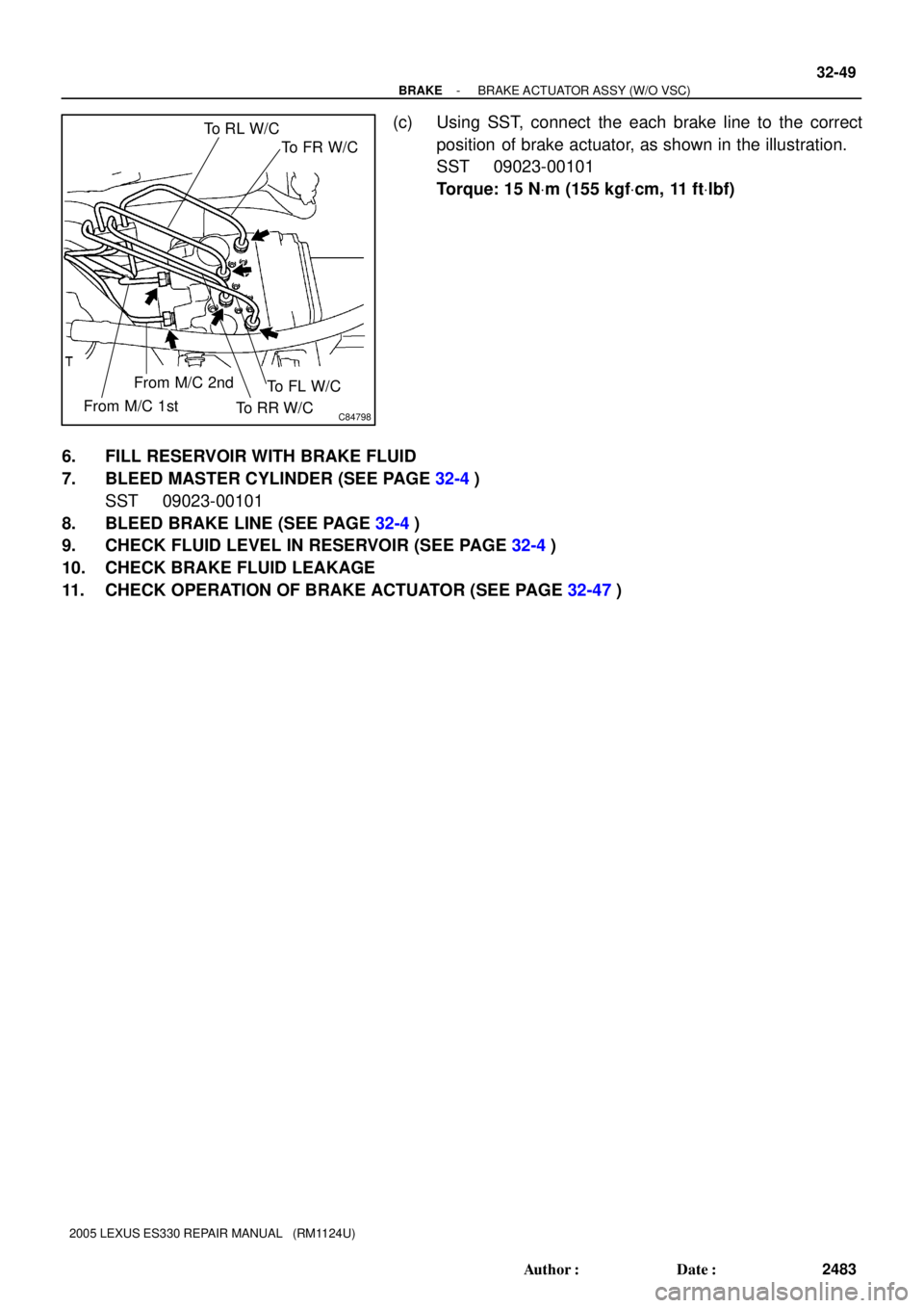
To RL W/C
To FR W/C
To FL W/C
To RR W/C From M/C 2nd
From M/C 1st
F40998
32-48
- BRAKEBRAKE ACTUATOR ASSY (W/O VSC)
2482 Author�: Date�:
2005 LEXUS ES330 REPAIR MANUAL (RM1124U)
REPLACEMENT
1. DRAIN BRAKE FLUID
NOTICE:
Wash off the brake fluid immediately if it comes into contact with a painted surface.
2. REMOVE BRAKE ACTUATOR WITH BRACKET
(a) Using SST, disconnect the 6 brake lines from the actuator.
SST 09023-00101
(b) Use tags or make a memo to identify the place to recon-
nect.
(c) Disconnect the brake actuator connector.
(d) Remove the 3 nuts and brake actuator with bracket.
3. REMOVE BRAKE ACTUATOR ASSY
(a) Remove the 2 nuts and brake actuator from the bracket.
(b) Remove the 2 holders and 3 cushions from the brake actuator.
4. INSTALL BRAKE ACTUATOR ASSY
(a) Install the 3 cushions and 2 holders to the brake actuator.
(b) Install the brake actuator to the bracket with the 2 nuts.
Torque: 5.4 NVm (55 kgfVcm, 48 in.Vlbf)
5. INSTALL BRAKE ACTUATOR WITH BRACKET
(a) Install the brake actuator with the 3 nuts.
Torque: 19 NVm (194 kgfVcm, 14 ftVlbf)
(b) Connect the brake actuator connector.
Page 294 of 969
C84798
To RL W/C
To FR W/C
To FL W/C
To RR W/C From M/C 2nd
From M/C 1st
- BRAKEBRAKE ACTUATOR ASSY (W/O VSC)
32-49
2483 Author�: Date�:
2005 LEXUS ES330 REPAIR MANUAL (RM1124U)
(c) Using SST, connect the each brake line to the correct
position of brake actuator, as shown in the illustration.
SST 09023-00101
Torque: 15 NVm (155 kgfVcm, 11 ftVlbf)
6. FILL RESERVOIR WITH BRAKE FLUID
7. BLEED MASTER CYLINDER (SEE PAGE 32-4)
SST 09023-00101
8. BLEED BRAKE LINE (SEE PAGE 32-4)
9. CHECK FLUID LEVEL IN RESERVOIR (SEE PAGE 32-4)
10. CHECK BRAKE FLUID LEAKAGE
11. CHECK OPERATION OF BRAKE ACTUATOR (SEE PAGE 32-47)
Page 297 of 969
F45683
F40999
C86250
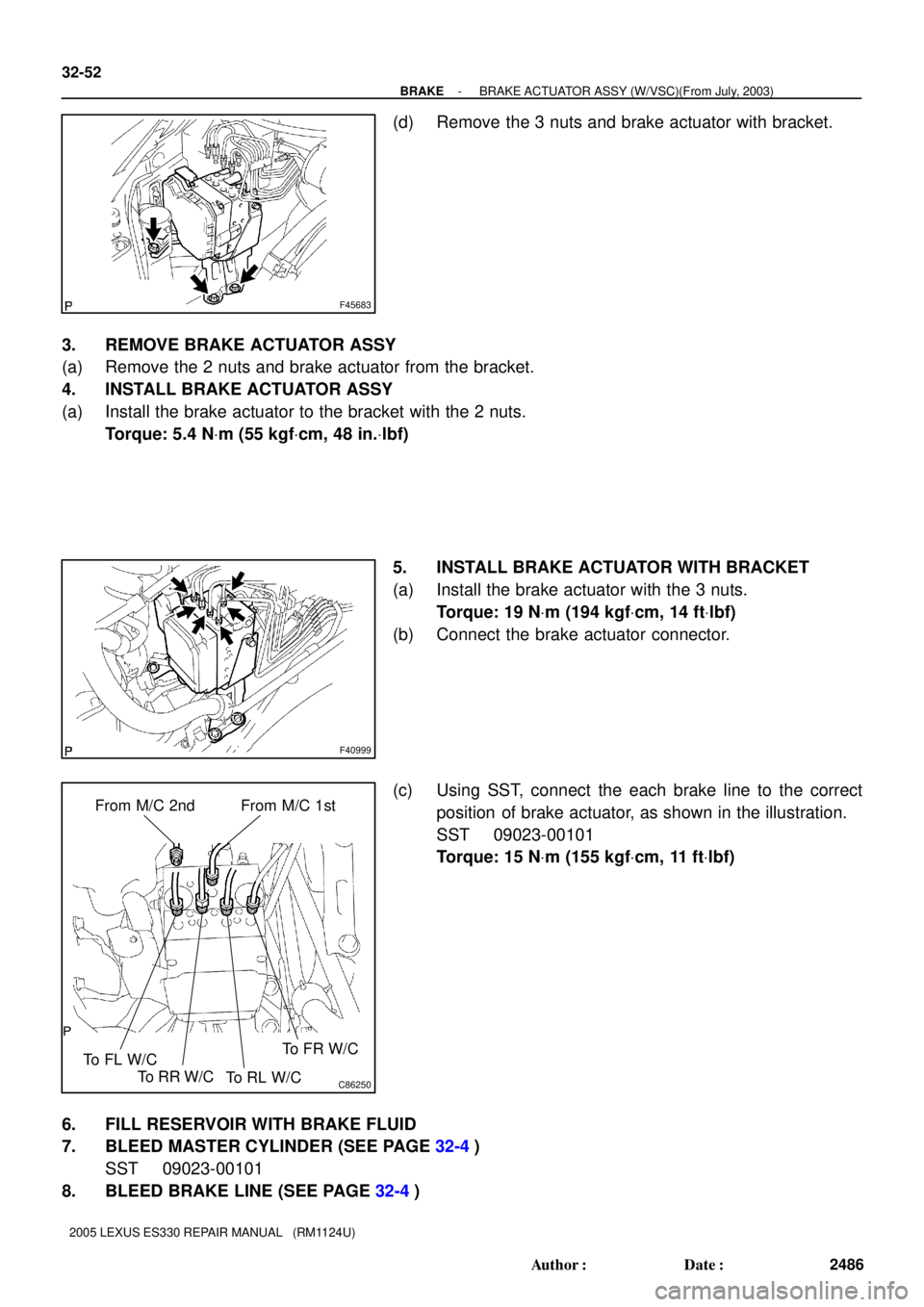
From M/C 2nd
To FL W/CFrom M/C 1st
To RR W/C
To RL W/CTo FR W/C
32-52
- BRAKEBRAKE ACTUATOR ASSY (W/VSC)(From July, 2003)
2486 Author�: Date�:
2005 LEXUS ES330 REPAIR MANUAL (RM1124U)
(d) Remove the 3 nuts and brake actuator with bracket.
3. REMOVE BRAKE ACTUATOR ASSY
(a) Remove the 2 nuts and brake actuator from the bracket.
4. INSTALL BRAKE ACTUATOR ASSY
(a) Install the brake actuator to the bracket with the 2 nuts.
Torque: 5.4 NVm (55 kgfVcm, 48 in.Vlbf)
5. INSTALL BRAKE ACTUATOR WITH BRACKET
(a) Install the brake actuator with the 3 nuts.
Torque: 19 NVm (194 kgfVcm, 14 ftVlbf)
(b) Connect the brake actuator connector.
(c) Using SST, connect the each brake line to the correct
position of brake actuator, as shown in the illustration.
SST 09023-00101
Torque: 15 NVm (155 kgfVcm, 11 ftVlbf)
6. FILL RESERVOIR WITH BRAKE FLUID
7. BLEED MASTER CYLINDER (SEE PAGE 32-4)
SST 09023-00101
8. BLEED BRAKE LINE (SEE PAGE 32-4)
Page 300 of 969
C84803
F41018F41017
A
B
F41016
- BRAKESPEED SENSOR FRONT LH
32-55
2489 Author�: Date�:
2005 LEXUS ES330 REPAIR MANUAL (RM1124U)
4. INSTALL SPEED SENSOR FRONT LH
(a) Install the speed sensor FR LH with the bolt.
Torque: 8.0 NVm (82 kgfVcm, 71 in.Vlbf)
NOTICE:
Make sure the sensor tip is clean.
(b) Install the sensor harness clamps with the 2 bolts ºAº and
ºBº to the body and shock absorber.
Torque:
Bolt A: 5.0 NVm (51 kgfVcm, 44 in.Vlbf)
Bolt B: 18.8 NVm (192 kgfVcm, 14 ftVlbf)
(c) Connect the clamp to the knuckle.
(d) Connect the speed sensor connector and clamp.
5. INSTALL FRONT FENDER LINER LH
6. INSTALL FRONT WHEEL
Torque: 103 NVm (1,050 kgfVcm, 76 ftVlbf)
7. CHECK ABS SPEED SENSOR SIGNAL (SEE PAGE 05-420 or 05-471)
Page 303 of 969
C83035
32-58
- BRAKESKID CONTROL SENSOR
2492 Author�: Date�:
2005 LEXUS ES330 REPAIR MANUAL (RM1124U)
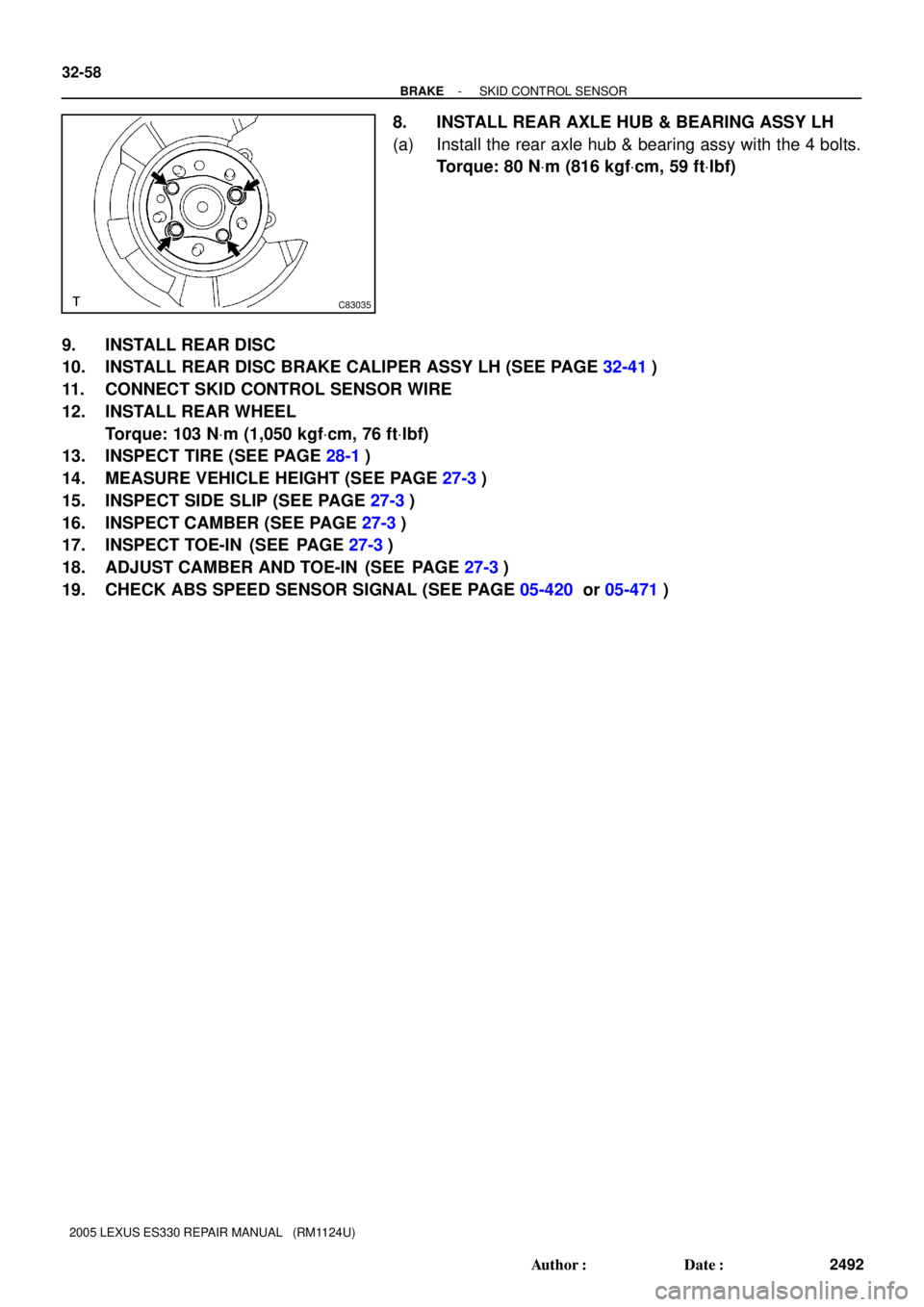
8. INSTALL REAR AXLE HUB & BEARING ASSY LH
(a) Install the rear axle hub & bearing assy with the 4 bolts.
Torque: 80 NVm (816 kgfVcm, 59 ftVlbf)
9. INSTALL REAR DISC
10. INSTALL REAR DISC BRAKE CALIPER ASSY LH (SEE PAGE 32-41)
11. CONNECT SKID CONTROL SENSOR WIRE
12. INSTALL REAR WHEEL
Torque: 103 NVm (1,050 kgfVcm, 76 ftVlbf)
13. INSPECT TIRE (SEE PAGE 28-1)
14. MEASURE VEHICLE HEIGHT (SEE PAGE 27-3)
15. INSPECT SIDE SLIP (SEE PAGE 27-3)
16. INSPECT CAMBER (SEE PAGE 27-3)
17. INSPECT TOE-IN (SEE PAGE 27-3)
18. ADJUST CAMBER AND TOE-IN (SEE PAGE 27-3)
19. CHECK ABS SPEED SENSOR SIGNAL (SEE PAGE 05-420 or 05-471)
Page 304 of 969
320E4-03
F45687
F45687
- BRAKEYAWRATE SENSOR (From July, 2003)
32-59
2493 Author�: Date�:
2005 LEXUS ES330 REPAIR MANUAL (RM1124U)
YAWRATE SENSOR (From July, 2003)
REPLACEMENT
NOTICE:
Do not separate the sensor from the bracket.
1. REMOVE CONSOLE PANEL UPPER REAR (SEE PAGE 71-1 1)
2. REMOVE RR CONSOLE BOX (SEE PAGE71-1 1 )
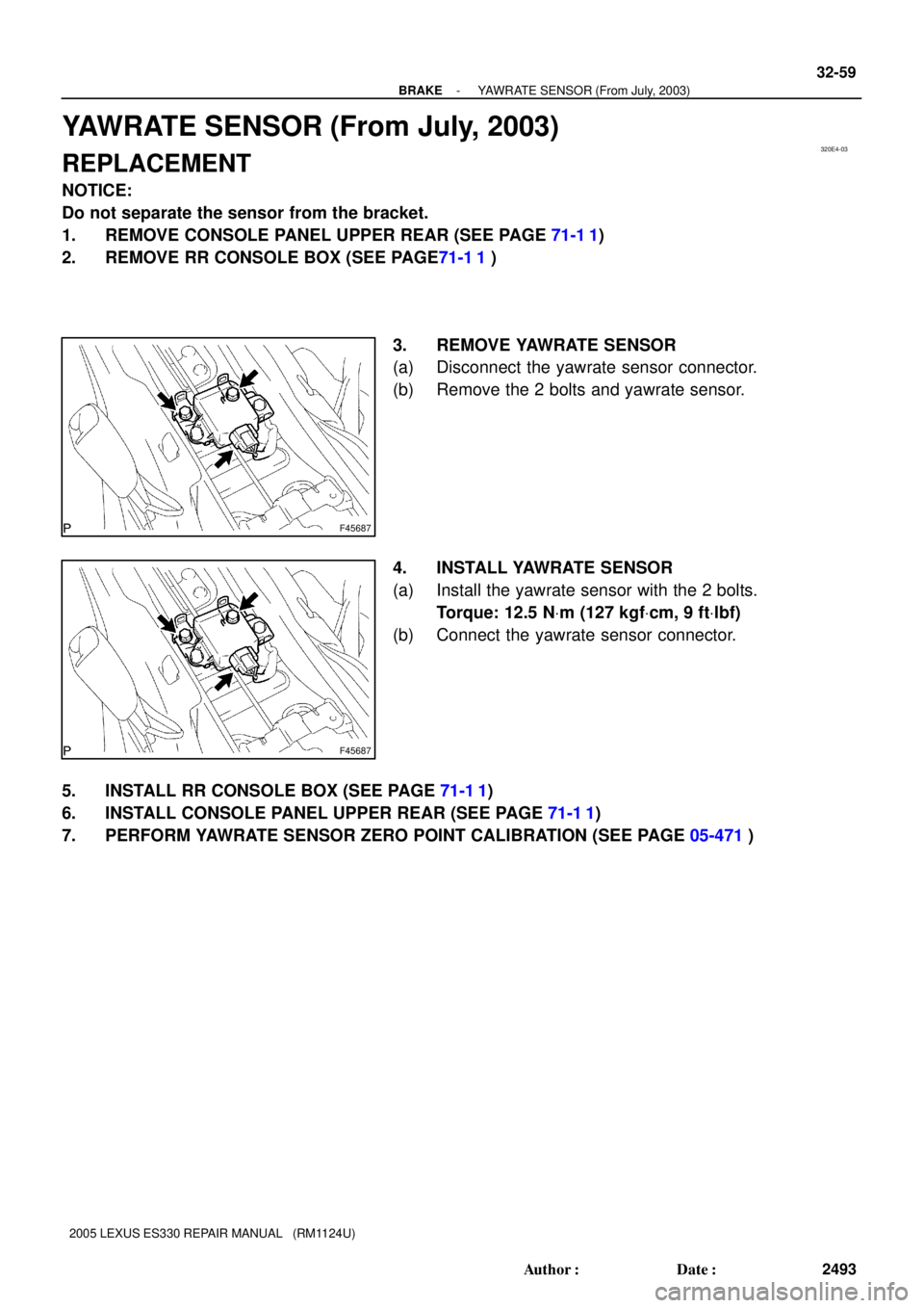
3. REMOVE YAWRATE SENSOR
(a) Disconnect the yawrate sensor connector.
(b) Remove the 2 bolts and yawrate sensor.
4. INSTALL YAWRATE SENSOR
(a) Install the yawrate sensor with the 2 bolts.
Torque: 12.5 NVm (127 kgfVcm, 9 ftVlbf)
(b) Connect the yawrate sensor connector.
5. INSTALL RR CONSOLE BOX (SEE PAGE 71-1 1)
6. INSTALL CONSOLE PANEL UPPER REAR (SEE PAGE 71-1 1)
7. PERFORM YAWRATE SENSOR ZERO POINT CALIBRATION (SEE PAGE 05-471)