Page 349 of 969
300AX-02
C91613
Front Drive Shaft
Assy LH Drive Shaft Bearing
Bracket Hole Snap Ring
Tie Rod Assy LH
Front Suspension
Arm Sub-assy Lower
No.1 LHFront Axle Assy LH Front Stabilizer Link Assy LH
Speed Sensor Front LH
� Cotter Pin Front Drive Shaft
Assy RH
N´m (kgf´cm, ft´lbf): Specified torque
� Non-reusable part
32 (330, 24)
8.0 (82, 71 in.Vlbf)
294 (2,998, 217)
49 (500, 36)
75 (765, 55)
� �
74 (755, 55)
Front Flexible Hose
No. 1
19 (192, 14)
� 30-4
- DRIVE SHAFT / PROPELLER SHAFTDRIVE SHAFT, PROPELLER SHAFT, AXLE (From July,
2003)
2407 Author�: Date�:
2005 LEXUS ES330 REPAIR MANUAL (RM1124U)
COMPONENTS
Page 351 of 969
G29148
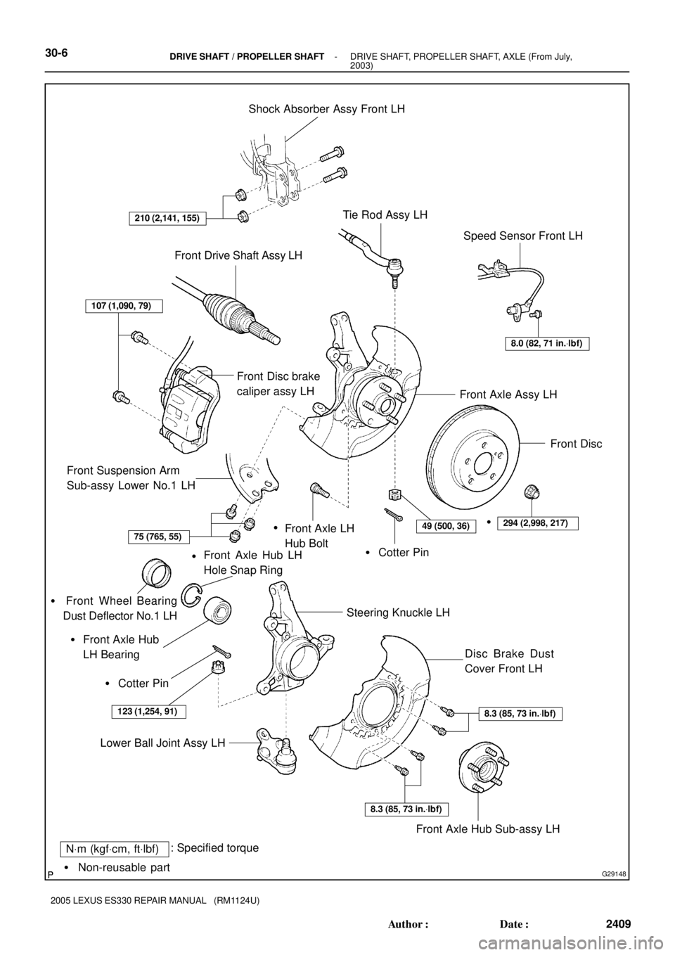
NVm (kgfVcm, ftVlbf): Specified torque
� Non-reusable partShock Absorber Assy Front LH
Tie Rod Assy LH
Speed Sensor Front LH
Front Suspension Arm
Sub-assy Lower No.1 LH
� Cotter Pin Front Axle LH
Hub Bolt
Steering Knuckle LH
Lower Ball Joint Assy LHFront Axle Assy LH Front Drive Shaft Assy LH
210 (2,141, 155)
8.0 (82, 71 in.Vlbf)
Front Disc
107 (1,090, 79)
75 (765, 55)49 (500, 36)294 (2,998, 217)
Front Axle Hub LH
Hole Snap Ring
� Cotter Pin�
Front Axle Hub
LH Bearing �
123 (1,254, 91)
Disc Brake Dust
Cover Front LH
Front Axle Hub Sub-assy LH
8.3 (85, 73 in.Vlbf)
8.3 (85, 73 in.Vlbf)
��
� Front Wheel Bearing
Dust Deflector No.1 LH
Front Disc brake
caliper assy LH
30-6- DRIVE SHAFT / PROPELLER SHAFTDRIVE SHAFT, PROPELLER SHAFT, AXLE (From July,
2003)
2409 Author�: Date�:
2005 LEXUS ES330 REPAIR MANUAL (RM1124U)
Page 352 of 969
C91585
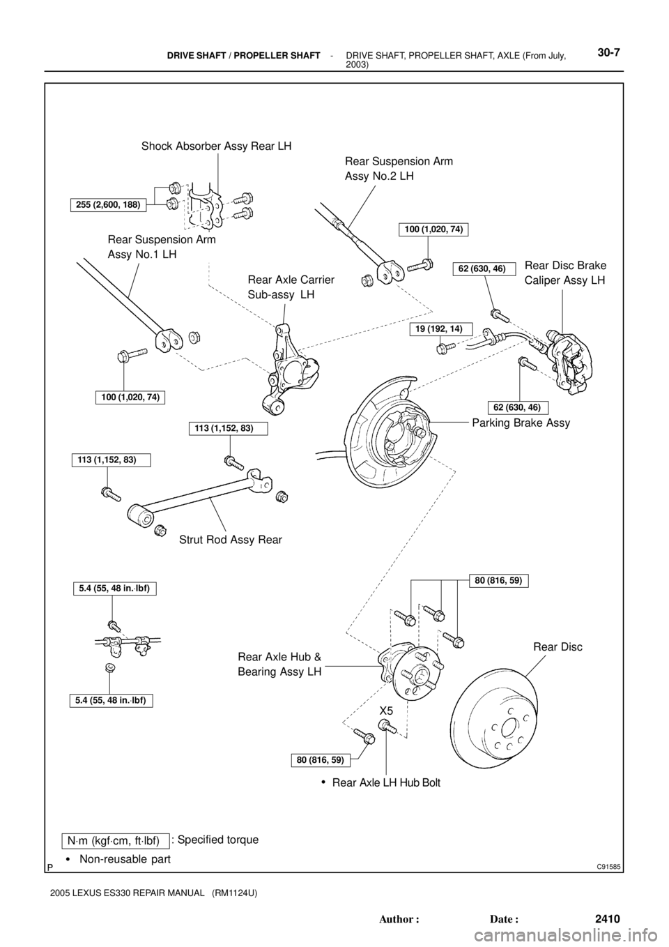
NVm (kgfVcm, ftVlbf): Specified torque
� Non-reusable partShock Absorber Assy Rear LH
Rear Suspension Arm
Assy No.2 LH
Rear Disc Brake
Caliper Assy LH Rear Axle Carrier
Sub-assy LH
Parking Brake Assy
Rear Axle Hub &
Bearing Assy LHRear Disc Strut Rod Assy Rear
100 (1,020, 74)
62 (630, 46)
100 (1,020, 74)
113 (1,152, 83)
113 (1,152, 83)
5.4 (55, 48 in.Vlbf)
5.4 (55, 48 in.Vlbf)
Rear Axle LH Hub Bolt
80 (816, 59)
X5
�
255 (2,600, 188)
19 (192, 14)
62 (630, 46)
80 (816, 59)
Rear Suspension Arm
Assy No.1 LH
- DRIVE SHAFT / PROPELLER SHAFTDRIVE SHAFT, PROPELLER SHAFT, AXLE (From July,
2003)30-7
2410 Author�: Date�:
2005 LEXUS ES330 REPAIR MANUAL (RM1124U)
Page 362 of 969

30-17
2420 Author�: Date�:
2005 LEXUS ES330 REPAIR MANUAL (RM1124U)
37. INSTALL FRONT DRIVE SHAFT ASSY RH
(a)")
C66548
F40142
C83022
- DRIVE SHAFT / PROPELLER SHAFTFRONT DRIVE SHAFT (From July, 2003)
30-17
2420 Author�: Date�:
2005 LEXUS ES330 REPAIR MANUAL (RM1124U)
37. INSTALL FRONT DRIVE SHAFT ASSY RH
(a) Using a screwdriver, install a new bearing bracket hole
snap ring.
NOTICE:
Do not damage the oil seal and boot.
(b) Install the bolt.
Torque: 32 NVm (330 kgfVcm, 24 ftVlbf)
38. INSTALL FRONT AXLE ASSY LH
(a) Install the front drive shaft assy LH to the front axle assy LH.
NOTICE:
�Be careful not to damage the outboard joint boot.
�Be careful not to damage the speed sensor rotor.
39. INSTALL FRONT SUSPENSION ARM SUB- ASSY
LOWER NO.1 LH
(a) Install the lower ball joint to the front suspension arm sub-
assy lower with the bolt and nuts.
Torque: 75 NVm (765 kgfVcm, 55 ftVlbf)
40. INSTALL TIE ROD ASSY LH
(a) Install the tie rod end to the steering knuckle with the nut.
Torque: 49 NVm (500 kgfVcm, 36 ftVlbf)
(b) Install a new cotter pin.
NOTICE:
If the holes for the cotter pin are not aligned, tighten the nut up to 60� further.
41. INSTALL SPEED SENSOR FRONT LH
(a) Install the flexible hose and the speed sensor to the shock
absorber with the bolt and set the clip of sensor on
knuckle.
Torque: 19 NVm (192 kgfVcm, 14 ftVlbf)
NOTICE:
�Be careful not to damage the speed sensor.
�Do not twist the sensor wire when installing the speed
sensor.
Page 363 of 969

2421 Author�: Date�:
2005 LEXUS ES330 REPAIR MANUAL (RM1124U)
(b) Install the speed sensor to the steeri")
F40147
F40136
F40152
30-18
- DRIVE SHAFT / PROPELLER SHAFTFRONT DRIVE SHAFT (From July, 2003)
2421 Author�: Date�:
2005 LEXUS ES330 REPAIR MANUAL (RM1124U)
(b) Install the speed sensor to the steering knuckle with the
bolt.
Torque: 8.0 NVm (82 kgfVcm, 71 in.Vlbf)
NOTICE:
Prevent foreign matter from adhering to the speed sensor.
42. INSTALL FRONT STABILIZER LINK ASSY LH
(a) Install the front stabilizer link assy LH with the nut.
Torque: 74 NVm (755 kgfVcm, 55 ftVlbf)
HINT:
If the ball joint turns together with the nut, use a hexagon (6 mm)
wrench to hold the stud.
43. INSTALL FRONT AXLE HUB LH NUT
(a) Using a socket wrench (30 mm), install a new axle hub LH
nut.
Torque: 294 NVm (2,998 kgfVcm, 217 ftVlbf)
(b) Using a chisel and hammer, stake the front axle hub LH
nut.
44. INSTALL FRONT WHEEL
Torque: 103 NVm (1,050 kgfVcm, 76 ftVlbf)
45. ADD AUTOMATIC TRANSAXLE FLUID (SEE PAGE 40-1)
46. INSPECT AUTOMATIC TRANSAXLE FLUID
47. INSPECT AND ADJUST FRONT WHEEL ALIGNMENT (SEE PAGE 26-5)
48. CHECK ABS SPEED SENSOR SIGNAL
w/ VSC (SEE PAGE 05-471)
w/o VSC (SEE PAGE 05-420)
Page 366 of 969

30-21
2424 Author�: Date�:
2005 LEXUS ES330 REPAIR MANUA")
F40230
SST
SST
F11547
SST
Spanner
V Block
F40231
SST
F40157
SST
SST
- DRIVE SHAFT / PROPELLER SHAFTFRONT AXLE HUB SUB-ASSY LH (From July, 2003)
30-21
2424 Author�: Date�:
2005 LEXUS ES330 REPAIR MANUAL (RM1124U)
14. REMOVE FRONT AXLE HUB LH BEARING
(a) Place the bearing inner race (outside) on the front axle
hub LH bearing.
(b) Using SST and a press, press the front axle hub LH bear-
ing until it contacts the SST.
SST 09527- 17011, 09950- 60010 (09951- 00600),
09950-70010 (09951-07100)
(c) Using a spanner to make the steering knuckle LH horizon-
tal, fix it to the V block as shown in the illustration.
NOTICE:
Be sure that the steering knuckle is horizontally posi-
tioned.
(d) Using SST and a press, remove the front axle hub LH
bearing.
SST 09950- 60010 (09951- 00600), 09950- 70010
(09951-07100)
15. INSTALL FRONT AXLE HUB LH BEARING
(a) Using SST and a press, install a new front axle hub LH
bearing to the steering knuckle LH.
SST 09950- 60020 (09951- 00790), 09950- 70010
(09951-07100)
16. INSTALL DISC BRAKE DUST COVER FRONT LH
(a) Place the disc brake dust cover front LH and using a torx wrench (T30), torque the 4 bolts.
Torque: 8.3 NVm (85 kgfVcm, 73 in.Vlbf)
17. INSTALL FRONT AXLE HUB SUB-ASSY LH
(a) Using SST and a press, install the front axle hub sub-
assy LH.
SST 09608- 32010, 09950- 60020 (09951- 00790),
09950-70010 (09951-07100)
Page 367 of 969

2425 Author�: Date�:
2005 LEXUS ES330 REPAIR MANUAL (RM1124U)
18. INSTALL FRONT AXL")
C83852F45465
C97690F45054
C83023
30-22
- DRIVE SHAFT / PROPELLER SHAFTFRONT AXLE HUB SUB-ASSY LH (From July, 2003)
2425 Author�: Date�:
2005 LEXUS ES330 REPAIR MANUAL (RM1124U)
18. INSTALL FRONT AXLE HUB LH HOLE SNAP RING
(a) Using snap ring pliers, install a new front axle hub LH hole
snap ring.
19. INSTALL FRONT WHEEL BEARING DUST
DEFLECTOR NO.1 LH
(a) Using SST and a hammer, install the bearing dust deflec-
tor No.1 LH.
SST 09316- 60011 (09316- 00011, 09316- 00031),
09608-32010
HINT:
Aligh the hole for the speed sensor in the bearing dust deflector
No.1 LH with the steering knuckle.
20. INSTALL LOWER BALL JOINT ASSY FRONT LH
(a) Install the lower ball joint assy front LH and tighten the nut.
Torque: 123 NVm (1,254 kgfVcm, 90 ftVlbf)
(b) Install a new cotter pin.
NOTICE:
If the holes for the cotter pin are not aligned, tighten the nut up to 60� further.
21. INSTALL FRONT AXLE ASSY LH
(a) Install the front axle assy LH with the 2 bolts and nuts to
the shock absorber assy front LH.
Torque: 210 NVm (2,141 kgfVcm, 155 ftVlbf)
NOTICE:
�Only when reusing the bolts and nuts, apply the small
amount of engine oil to the screw part of the nuts.
�Do not excessively push out the front axle assy LH.
�Be careful not to damage the outboard joint boot.
�Be careful not to damage the speed sensor rotor.
22. INSTALL FRONT SUSPENSION ARM SUB-ASSY LOWER NO.1 LH (SEE PAGE 30-8)
23. INSTALL TIE ROD ASSY LH (SEE PAGE 30-8)
24. INSTALL FRONT DISC
Page 368 of 969

30-23
2426 Author�: Date�:
2005 LEXUS ES330 REPAIR MANUAL (RM1124U)
25. INSTALL FRONT DISC BRA")
C91612
C91612
F40163
F40164
- DRIVE SHAFT / PROPELLER SHAFTFRONT AXLE HUB SUB-ASSY LH (From July, 2003)
30-23
2426 Author�: Date�:
2005 LEXUS ES330 REPAIR MANUAL (RM1124U)
25. INSTALL FRONT DISC BRAKE CALIPER ASSY LH
(a) Install the front disc brake caliper assy LH with the 2 bolts
to the steering knuckle LH.
Torque: 107 NVm (1,090 kgfVcm, 79 ftVlbf)
26. INSTALL FRONT AXLE HUB LH NUT (SEE PAGE30-8)
(a) Using a socket wrench (30 mm), install a new axle hub LH nut.
Torque: 294 NVm (2,998 kgfVcm, 217 ftVlbf)
27. DISCONNECT FRONT DISC BRAKE CALIPER ASSY
LH
(a) Remove the 2 bolts and separate the front disc brake cali-
per assy LH from the steering knuckle LH.
NOTICE:
Use a string or other device to keep the brake caliper from
hanging down by the flexible hose.
28. REMOVE FRONT DISC
29. INSPECT BEARING BACKLASH
(a) Using a dial indicator, check the backlash near the center
of the axle hub.
Maximum: 0.05 mm (0.0020 in.)
If the backlash exceeds the maximum, replace the bearing.
30. INSPECT AXLE HUB DEVIATION
(a) Using a dial indicator, check the deviation at the surface
of the axle hub outside the hub bolt.
Maximum: 0.05 mm (0.0020 in.)
If the deviation exceeds the maximum, replace the axle hub.