Page 415 of 969
- ENGINE MECHANICALPARTIAL ENGINE ASSY (3MZ-FE)
14-39
2131 Author�: Date�:
2005 LEXUS ES330 REPAIR MANUAL (RM1124U)
157. ADD AUTOMATIC TRANSAXLE FLUID
158. ADD ENGINE OIL (See page 17-20)
159. ADD COOLANT (See page 16-9)
160. ADD POWER STEERING FLUID
161. BLEED POWER STEERING FLUID
162. INSPECT AUTOMATIC TRANSAXLE FLUID (See page 40-1)
163. CHECK FOR ENGINE OIL LEAKS
164. CHECK FOR ENGINE COOLANT LEAKS (See page 16-1)
165. CHECK POWER STEERING FLUID LEAKAGE
166. INSPECT FOR FUEL LEAKS
167. CHECK FOR EXHAUST GAS LEAKS
168. INSPECT AND ADJUST FRONT WHEEL ALIGNMENT (See page 26-5)
169. INSPECT STEERING WHEEL CENTER POINT
170. INSPECT IGNITION TIMING (See page 14-1)
SST 09843-18040
171. INSPECT ENGINE IDLE SPEED (See page 14-1)
172. INSPECT CO/HC (See page 14-1)
173. CHECK ABS SPEED SENSOR SIGNAL (See page 05-420, 05-471)
174. SYSTEM INITIALIZATION (See page 19-15)
Page 722 of 969
F40143
- FRONT SUSPENSIONSTABILIZER BAR FRONT
26-19
2382 Author�: Date�:
2005 LEXUS ES330 REPAIR MANUAL (RM1124U)
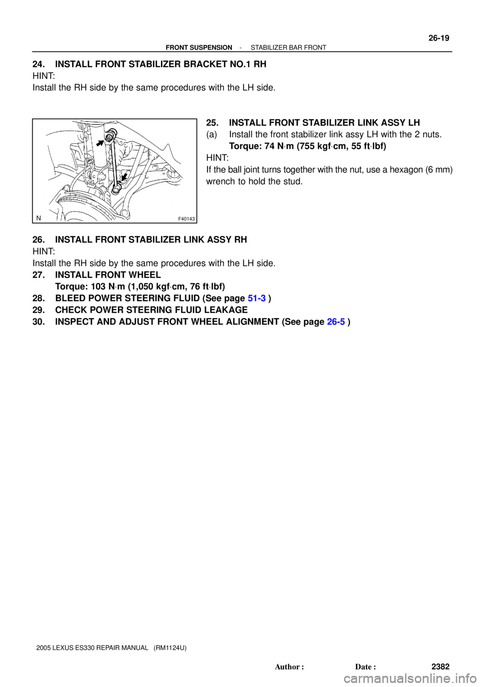
24. INSTALL FRONT STABILIZER BRACKET NO.1 RH
HINT:
Install the RH side by the same procedures with the LH side.
25. INSTALL FRONT STABILIZER LINK ASSY LH
(a) Install the front stabilizer link assy LH with the 2 nuts.
Torque: 74 NVm (755 kgfVcm, 55 ftVlbf)
HINT:
If the ball joint turns together with the nut, use a hexagon (6 mm)
wrench to hold the stud.
26. INSTALL FRONT STABILIZER LINK ASSY RH
HINT:
Install the RH side by the same procedures with the LH side.
27. INSTALL FRONT WHEEL
Torque: 103 NVm (1,050 kgfVcm, 76 ftVlbf)
28. BLEED POWER STEERING FLUID (See page 51-3)
29. CHECK POWER STEERING FLUID LEAKAGE
30. INSPECT AND ADJUST FRONT WHEEL ALIGNMENT (See page 26-5)
Page 724 of 969

PROBLEM SYMPTOMS TABLE
HINT:
Use the table below to help you find the cause of the p")
51017-12
51-2
- POWER STEERINGPOWER STEERING SYSTEM
2577 Author�: Date�:
2005 LEXUS ES330 REPAIR MANUAL (RM1124U)
PROBLEM SYMPTOMS TABLE
HINT:
Use the table below to help you find the cause of the problem. The numbers indicate the priority of the likely
cause of the problem. Check each part in the order shown. If necessary, repair or replace these parts.
SymptomSuspect AreaSee page
Hard steering
1. Tires (Improperly inflated)
2. Power steering fluid level (Low)
3. Drive belt (Loose)
4. Front wheel alignment (Incorrect)
5. Steering system joints (Worn)
6. Suspension arm ball joints (Worn)
7. Steering column (Binding)
8. Vane pump assy
9. Rack & pinion power steering gear assy28-1
51-3
14-1
26-5
-
26-16
-
51-9
51-21
Poor return
1. Tires (Improperly inflated)
2. Front wheel alignment (Incorrect)
3. Steering column (Binding)
4. Rack & pinion power steering gear assy28-1
26-5
-
51-21
Excessive play
1. Steering system joints (Worn)
2. Suspension arm ball joints (Worn)
3. Steering intermediate shaft sub-assy (Worn)
4. Sliding yoke (Worn)
5. Front wheel bearing (Worn)
6. Rack & pinion power steering gear assy-
26-16
-
-
30-2
51-21
Abnormal noise
1. Power steering fluid level (Low)
2. Steering system joints (Worn)
3. Vane pump assy
4. Rack & pinion power steering gear assy51-3
-
51-9
51-21
Page 725 of 969
 Visually check the belt for excessive wea")
51018-15
F40449
F40897
Normal
Abnormal
F40898
- POWER STEERINGPOWER STEERING SYSTEM
51-3
2578 Author�: Date�:
ON-VEHICLE INSPECTION
1. INSPECT DRIVE BELT
(a) Visually check the belt for excessive wear, frayed cords,
etc.
If any defect is found, replace the drive belt.
HINT:
Cracks on the rib side of a belt are considered acceptable. If the
missing chunks from the ribs are found on the belt, it should be
replaced.
2. BLEED POWER STEERING SYSTEM
(a) Check the fluid level.
(b) Jack up the front of the vehicle and support it with the
stands.
(c) Turn the steering wheel.
(1) With the engine stopped, turn the wheel slowly from
lock to lock several times.
(d) Lower the vehicle.
(e) Start the engine.
(1) Run the engine at idle for a few minutes.
(f) Turn the steering wheel.
(1) With the engine idling, turn the wheel to left or right
full lock position and keep it there for 2 - 3 seconds,
then turn the wheel to the opposite full lock position
and keep it there for 2 - 3 seconds.
(2) Repeat (1) several times.
(g) Stop the engine.
(h) Check for forming or emulsification.
Especially, if the system has to be bled twice because of foam-
ing or emulsification, check for fluid leaks in the system.
(i) Check the fluid level.
3. CHECK FLUID LEVEL
(a) Keep the vehicle level.
(b) With the engine stopped, check the fluid level in the oil
reservoir.
If necessary, add fluid.
Fluid: ATF DEXRON® II or III
HINT:
Check that the fluid level is within the HOT LEVEL range on the
reservoir cap. If the fluid is cold, check that it is within the COLD
LEVEL range.
Page 726 of 969

or less 51-4
- POWER STEERINGPOWER STEERING SYSTEM
2579 Author�: Date�:
(c) Start the engine and run it at idle.
(d) Turn the st")
F40897
NormalAbnormal
R11786Engine Idling Engine Stopped5 mm (0.20 in.)
or less 51-4
- POWER STEERINGPOWER STEERING SYSTEM
2579 Author�: Date�:
(c) Start the engine and run it at idle.
(d) Turn the steering wheel from lock to lock several times to
raise fluid temperature.
Fluid temperature: 75 - 80°C (167 - 176°F)
(e) Check for foaming or emulsification.
If foaming or emulsification is identified, bleed the power steer-
ing system.
(f) With the engine idling, measure the fluid level in the oil
reservoir.
(g) Stop the engine.
(h) Wait a few minutes and remeasure the fluid level in the oil
reservoir.
Maximum fluid level rise: 5 mm (0.20 in.)
If a problem is found, bleed the power steering system.
(i) Check the fluid level.
4. CHECK STEERING FLUID PRESSURE
(a) Disconnect the pressure feed tube assy from the rack &
pinion power steering gear assy (See page 51-21).
(b) Connect SST, as shown in the illustration.
SST 09640-10010 (09641-01010, 09641-01020,
09641-01030)
NOTICE:
Check that the valve of the SST is in the open position.
(c) Bleed the power steering system.
(d) Start the engine and run it at idle.
(e) Turn the steering wheel from lock to lock several times to
raise fluid temperature.
Fluid temperature: 75 - 80 °C (167 - 176 °F)
Page 727 of 969

F41520
SST
OUT Attachment
Pressure Feed
Tube AssyAttachment
IN
Z15498
Oil
Reservoir
PS Vane
Pump PS Gear
SST Closed
Z15499
Oil
Reservoir
PS Vane
Pump PS Gear
SST Open
Z15500
Oil
Reservoir
PS Vane
Pump PS Gear
SST Open Lock Position
- POWER STEERINGPOWER STEERING SYSTEM
51-5
2580 Author�: Date�:
(f) With the engine idling, close the valve of the SST and ob-
serve the reading on the SST.
Fluid pressure:
7,800 - 8,300 kPa (80 - 85 kgf/cm
2, 1,138 - 1,209 psi)
NOTICE:
�Do not keep the valve closed for more than 10 se-
conds.
�Do not let the fluid temperature become too high.
(g) With the engine idling, open the valve fully.
(h) Measure the fluid pressure at engine speeds of 1,000 rpm
and 3,000 rpm.
Fluid pressure difference:
490 kPa (5 kgf/cm
2, 71 psi) or less
NOTICE:
Do not turn the steering wheel.
(i) With the engine idling and valve fully opened, turn the
steering wheel to full lock position.
Fluid pressure:
7,800 - 8,300 kPa (80 - 85 kgf/cm
2, 1,138 - 1,209 psi)
NOTICE:
�Do not maintain lock position for more than 10 se-
conds.
�Do not let the fluid temperature become too high.
Page 729 of 969
51068-01
F41597
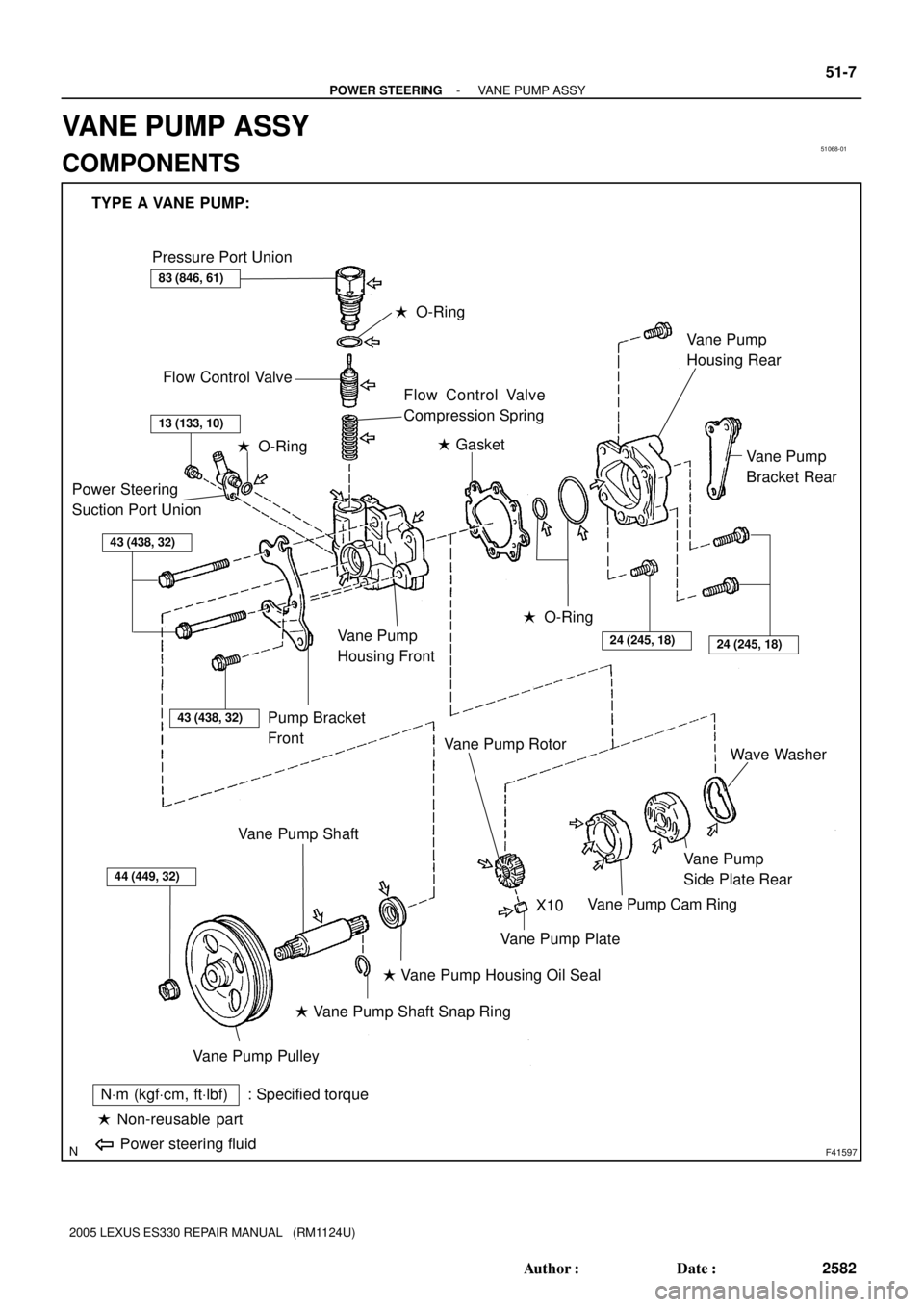
TYPE A VANE PUMP:
Pressure Port Union
Flow Control Valve
� O-Ring
Flow Control Valve
Compression Spring
Power Steering
Suction Port Union
43 (438, 32)
Pump Bracket
Front
Vane Pump
Housing Front
� O-Ring� Gasket
� O-Ring
24 (245, 18)24 (245, 18)
Vane Pump
Bracket Rear Vane Pump
Housing Rear
44 (449, 32)
Vane Pump Pulley
Vane Pump Shaft
� Vane Pump Shaft Snap Ring
� Vane Pump Housing Oil Seal
Vane Pump Plate
Vane Pump Rotor
Vane Pump Cam Ring
Vane Pump
Side Plate RearWave Washer
� Non-reusable part
NVm (kgfVcm, ftVlbf) : Specified torque
Power steering fluid
X10
83 (846, 61)
13 (133, 10)
43 (438, 32)
- POWER STEERINGVANE PUMP ASSY
51-7
2582 Author�: Date�:
2005 LEXUS ES330 REPAIR MANUAL (RM1124U)
VANE PUMP ASSY
COMPONENTS
Page 730 of 969
F41589
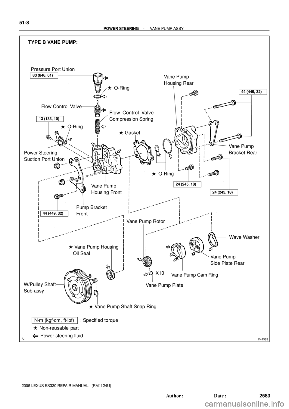
TYPE B VANE PUMP:
Pressure Port Union
� O-Ring
Flow Control Valve
Flow Control Valve
Compression Spring
� Gasket
Power Steering
Suction Port Union
� O-Ring
Pump Bracket
Front
Vane Pump
Housing Front
� O-Ring
24 (245, 18)
24 (245, 18)
Vane Pump
Housing Rear
Wave Washer
Vane Pump
Side Plate Rear
Vane Pump Cam Ring
Vane Pump Plate
� Vane Pump Shaft Snap Ring W/Pulley Shaft
Sub-assy� Vane Pump Housing
Oil Seal
� Non-reusable part
NVm (kgfVcm, ftVlbf) : Specified torque
Power steering fluid
Vane Pump
Bracket Rear
X10
Vane Pump Rotor
83 (846, 61)
13 (133, 10)
44 (449, 32)
44 (449, 32)
51-8
- POWER STEERINGVANE PUMP ASSY
2583 Author�: Date�:
2005 LEXUS ES330 REPAIR MANUAL (RM1124U)