Page 822 of 2870

FU(H4SO)-40
FUEL INJECTION (FUEL SYSTEM)
Front Oxygen (A/F) Sensor
14.Front Oxygen (A/F) Sensor
A: REMOVAL
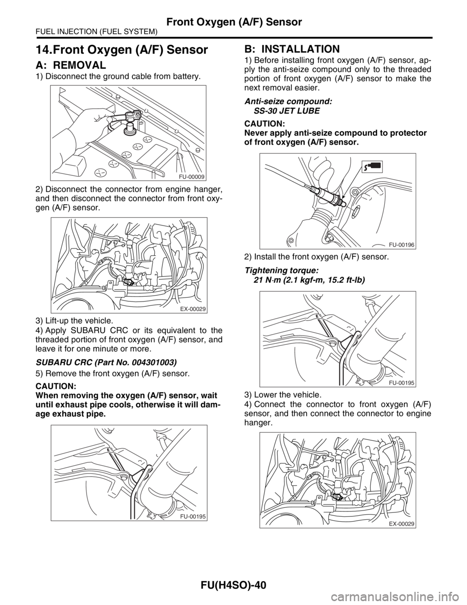
1) Disconnect the ground cable from battery.
2) Disconnect the connector from engine hanger,
and then disconnect the connector from front oxy-
gen (A/F) sensor.
3) Lift-up the vehicle.
4) Apply SUBARU CRC or its equivalent to the
threaded portion of front oxygen (A/F) sensor, and
leave it for one minute or more.
SUBARU CRC (Part No. 004301003)
5) Remove the front oxygen (A/F) sensor.
CAUTION:
When removing the oxygen (A/F) sensor, wait
until exhaust pipe cools, otherwise it will dam-
age exhaust pipe.
B: INSTALLATION
1) Before installing front oxygen (A/F) sensor, ap-
ply the anti-seize compound only to the threaded
portion of front oxygen (A/F) sensor to make the
next removal easier.
Anti-seize compound:
SS-30 JET LUBE
CAUTION:
Never apply anti-seize compound to protector
of front oxygen (A/F) sensor.
2) Install the front oxygen (A/F) sensor.
Tightening torque:
21 N
⋅m (2.1 kgf-m, 15.2 ft-lb)
3) Lower the vehicle.
4) Connect the connector to front oxygen (A/F)
sensor, and then connect the connector to engine
hanger.
FU-00009
EX-00029
FU-00195
FU-00196
FU-00195
EX-00029
Page 823 of 2870
FU(H4SO)-41
FUEL INJECTION (FUEL SYSTEM)
Front Oxygen (A/F) Sensor
5) Connect the battery ground cable to battery.
FU-00009
Page 824 of 2870

FU(H4SO)-42
FUEL INJECTION (FUEL SYSTEM)
Rear Oxygen Sensor
15.Rear Oxygen Sensor
A: REMOVAL
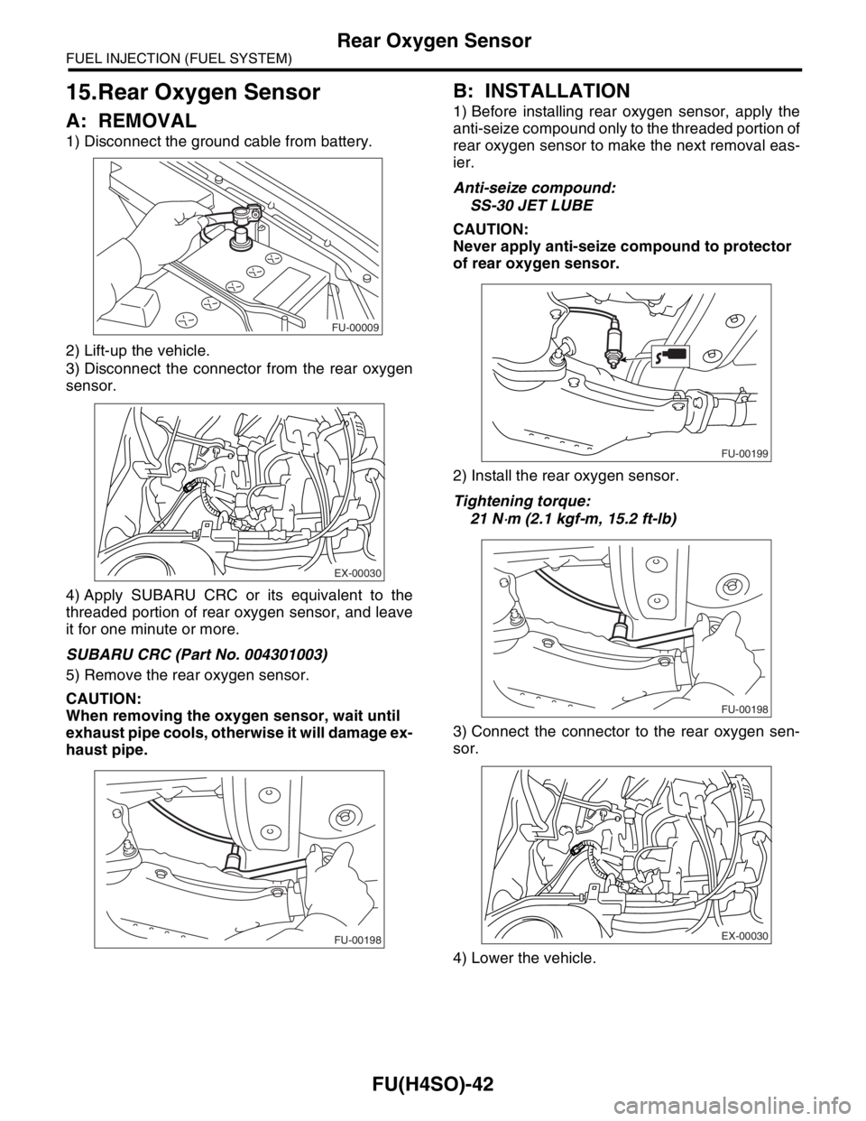
1) Disconnect the ground cable from battery.
2) Lift-up the vehicle.
3) Disconnect the connector from the rear oxygen
sensor.
4) Apply SUBARU CRC or its equivalent to the
threaded portion of rear oxygen sensor, and leave
it for one minute or more.
SUBARU CRC (Part No. 004301003)
5) Remove the rear oxygen sensor.
CAUTION:
When removing the oxygen sensor, wait until
exhaust pipe cools, otherwise it will damage ex-
haust pipe.
B: INSTALLATION
1) Before installing rear oxygen sensor, apply the
anti-seize compound only to the threaded portion of
rear oxygen sensor to make the next removal eas-
ier.
Anti-seize compound:
SS-30 JET LUBE
CAUTION:
Never apply anti-seize compound to protector
of rear oxygen sensor.
2) Install the rear oxygen sensor.
Tightening torque:
21 N
⋅m (2.1 kgf-m, 15.2 ft-lb)
3) Connect the connector to the rear oxygen sen-
sor.
4) Lower the vehicle.
FU-00009
EX-00030
FU-00198
FU-00199
FU-00198
EX-00030
Page 825 of 2870
FU(H4SO)-43
FUEL INJECTION (FUEL SYSTEM)
Rear Oxygen Sensor
5) Connect the battery ground cable to battery.
FU-00009
Page 826 of 2870
FU(H4SO)-44
FUEL INJECTION (FUEL SYSTEM)
Engine Control Module (ECM)
16.Engine Control Module (ECM)
A: REMOVAL
1) Disconnect the ground cable from battery.
2) Remove the lower inner trim of passenger side.
3) Detach the floor mat of front passenger seat.
4) Remove the protect cover.
5) Remove the nuts (A) which hold ECM to the
bracket.
6) Remove the clip (B) from the bracket.
7) Disconnect the ECM connectors and take out
the ECM.
B: INSTALLATION
Install in the reverse order of removal.
CAUTION:
When replacing ECM, be careful not to use the
wrong spec. ECM to avoid any damage to the
fuel injection system.
Tightening torque:
5 N
⋅m (0.51 kgf-m, 3.7 ft-lb)
FU-00009
FU-00315
(A)
(A)
(B)
FU-00316
Page 827 of 2870
FU(H4SO)-45
FUEL INJECTION (FUEL SYSTEM)
Main Relay
17.Main Relay
A: REMOVAL
1) Disconnect the ground cable from battery.
2) Remove the passenger’s side front side sill cov-
er.
3) Remove the bolt which holds main bracket on
the body.
4) Disconnect the connectors from the main relay.
B: INSTALLATION
Install in the reverse order of removal.
FU-00009
FU-00317
Page 828 of 2870
FU(H4SO)-46
FUEL INJECTION (FUEL SYSTEM)
Fuel Pump Relay
18.Fuel Pump Relay
A: REMOVAL
1) Disconnect the ground cable from battery.
2) Remove the passenger’s side front side sill cov-
er.
3) Remove the bolt which holds fuel pump relay
bracket on the body.
4) Disconnect the connector from the fuel pump.
5) Remove the fuel pump relay from the mounting
bracket.
B: INSTALLATION
Install in the reverse order of removal.
FU-00009
FU-00262
Page 829 of 2870
FU(H4SO)-47
FUEL INJECTION (FUEL SYSTEM)
Fuel
19.Fuel
A: OPERATION
1. RELEASING OF FUEL PRESSURE
WARNING:
Place “NO FIRE” signs near the working area.
Be careful not to spill fuel.
1) Disconnect the connector from fuel pump relay.
2) Start the engine and run it until it stalls.
3) After the engine stalls, crank it for 5 more sec-
onds.
4) Turn the ignition switch to OFF.
2. DRAINING FUEL
WARNING:
Place “NO FIRE” signs near the working area.
Be careful not to spill fuel.
1) Set the vehicle on a lift.
2) Disconnect the ground cable from battery.
3) Open the fuel filler flap lid and remove fuel filler
cap.
4) Lift-up the vehicle.5) Drain fuel from the fuel tank.
Set a container under the vehicle and remove the
drain plug from fuel tank.
6) Tighten the fuel drain plug.
Tightening torque:
26 N
⋅m (2.7 kgf-m, 19.2 ft-lb)
FU-00262
FU-00009
FU-00089
FU-00089