2004 SUBARU FORESTER fuel
[x] Cancel search: fuelPage 894 of 2870
ME(H4SO)-25
MECHANICAL
Compression
2. Compression
A: INSPECTION
CAUTION:
After warming-up, engine becomes very hot. Be
careful not to burn yourself during measure-
ment.
1) After warming-up the engine, turn the ignition
switch to OFF.
2) Make sure that the battery is fully charged.
3) Release the fuel pressure.
TION, Fuel.>
4) Remove all the spark plugs.
5) Fully open the throttle valve.
6) Check the starter motor for satisfactory perfor-
mance and operation.
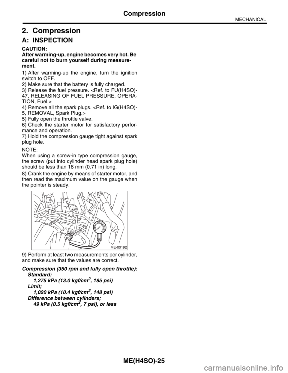
7) Hold the compression gauge tight against spark
plug hole.
NOTE:
When using a screw-in type compression gauge,
the screw (put into cylinder head spark plug hole)
should be less than 18 mm (0.71 in) long.
8) Crank the engine by means of starter motor, and
then read the maximum value on the gauge when
the pointer is steady.
9) Perform at least two measurements per cylinder,
and make sure that the values are correct.
Compression (350 rpm and fully open throttle):
Standard;
1,275 kPa (13.0 kgf/cm
2, 185 psi)
Limit;
1,020 kPa (10.4 kgf/cm
2, 148 psi)
Difference between cylinders;
49 kPa (0.5 kgf/cm
2, 7 psi), or less
ME-00192
Page 899 of 2870
ME(H4SO)-30
MECHANICAL
Fuel Pressure
7. Fuel Pressure
A: INSPECTION
WARNING:
Before removing the fuel pressure gauge, re-
lease the fuel pressure.
NOTE:
If out of specification, check or replace the pressure
regulator and pressure regulator vacuum hose.
1) Release the fuel pressure.
TION, Fuel.>
2) Open the fuel flap lid, and then remove the fuel
filler cap.
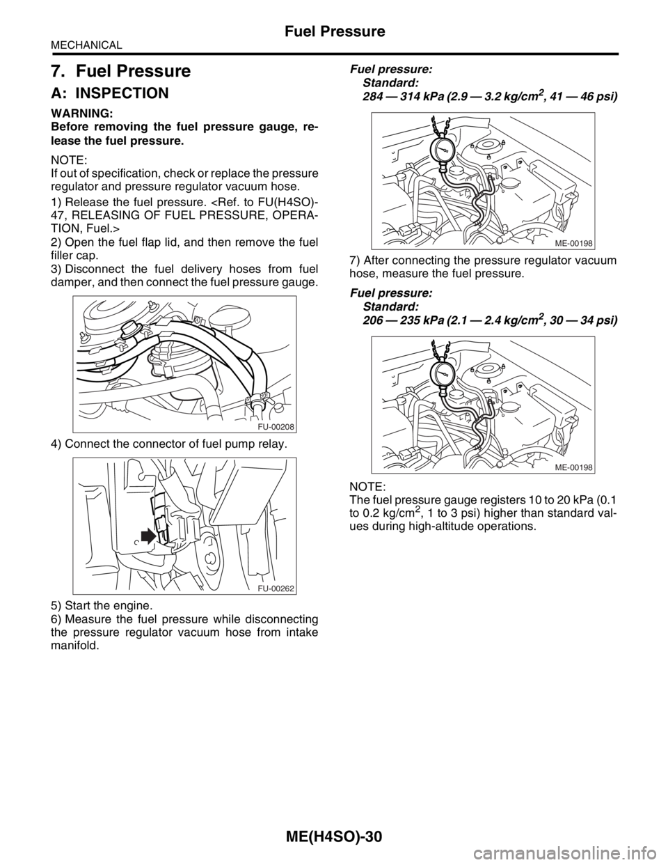
3) Disconnect the fuel delivery hoses from fuel
damper, and then connect the fuel pressure gauge.
4) Connect the connector of fuel pump relay.
5) Start the engine.
6) Measure the fuel pressure while disconnecting
the pressure regulator vacuum hose from intake
manifold.Fuel pressure:
Standard:
284 — 314 kPa (2.9 — 3.2 kg/cm
2, 41 — 46 psi)
7) After connecting the pressure regulator vacuum
hose, measure the fuel pressure.
Fuel pressure:
Standard:
206 — 235 kPa (2.1 — 2.4 kg/cm
2, 30 — 34 psi)
NOTE:
The fuel pressure gauge registers 10 to 20 kPa (0.1
to 0.2 kg/cm
2, 1 to 3 psi) higher than standard val-
ues during high-altitude operations.
FU-00208
FU-00262
ME-00198
ME-00198
Page 903 of 2870
ME(H4SO)-34
MECHANICAL
Engine Assembly
9. Engine Assembly
A: REMOVAL
1) Set the vehicle on lift arms.
2) Open the front hood fully, and then support with
the front hood stay.
3) Release the fuel pressure.
TION, Fuel.>
4) Disconnect the A/C pressure hoses from A/C
compressor.
5) Remove the fuel filler cap.
6) Disconnect the ground cable from battery.
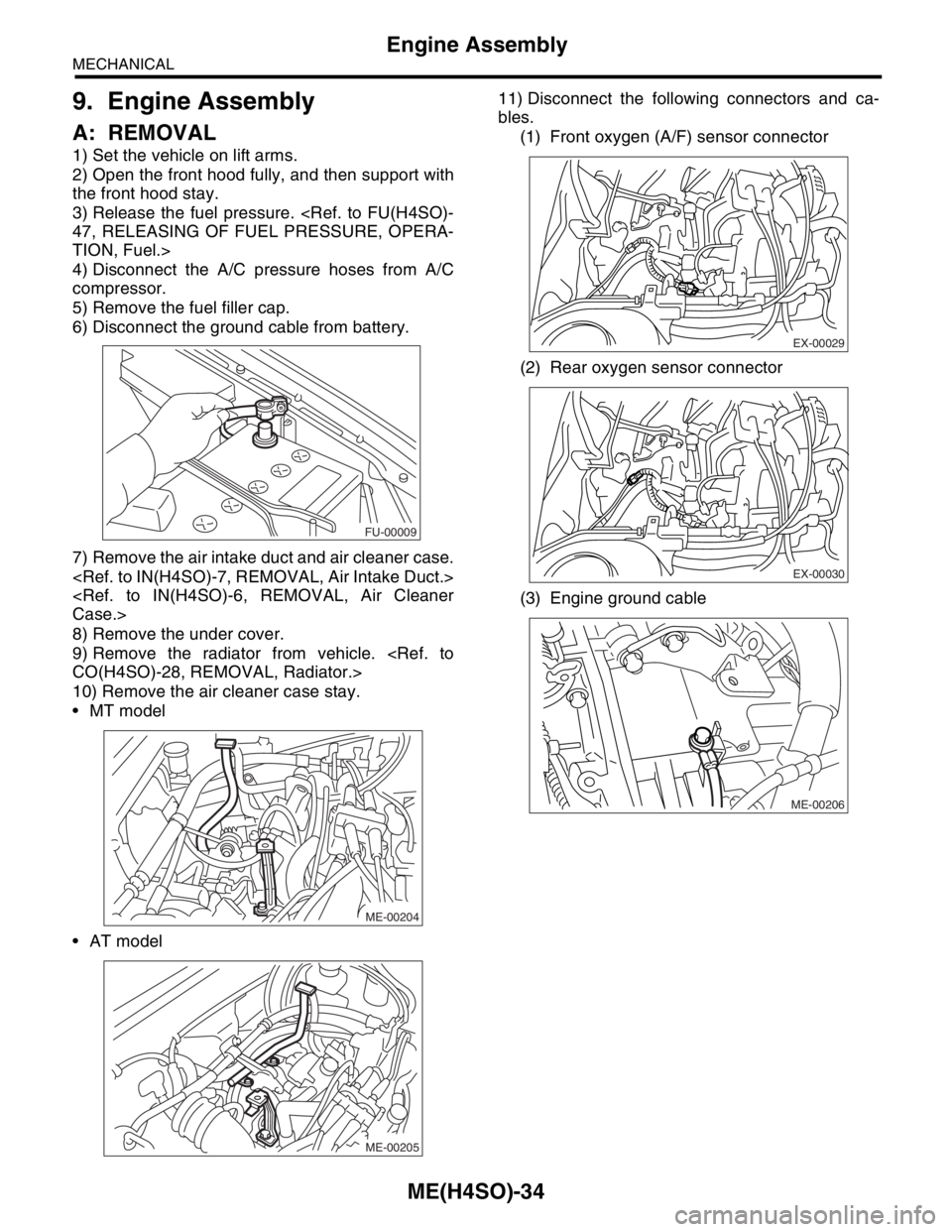
7) Remove the air intake duct and air cleaner case.
8) Remove the under cover.
9) Remove the radiator from vehicle.
10) Remove the air cleaner case stay.
MT model
AT model11) Disconnect the following connectors and ca-
bles.
(1) Front oxygen (A/F) sensor connector
(2) Rear oxygen sensor connector
(3) Engine ground cable
FU-00009
ME-00204
ME-00205
EX-00029
EX-00030
ME-00206
Page 906 of 2870
ME(H4SO)-37
MECHANICAL
Engine Assembly
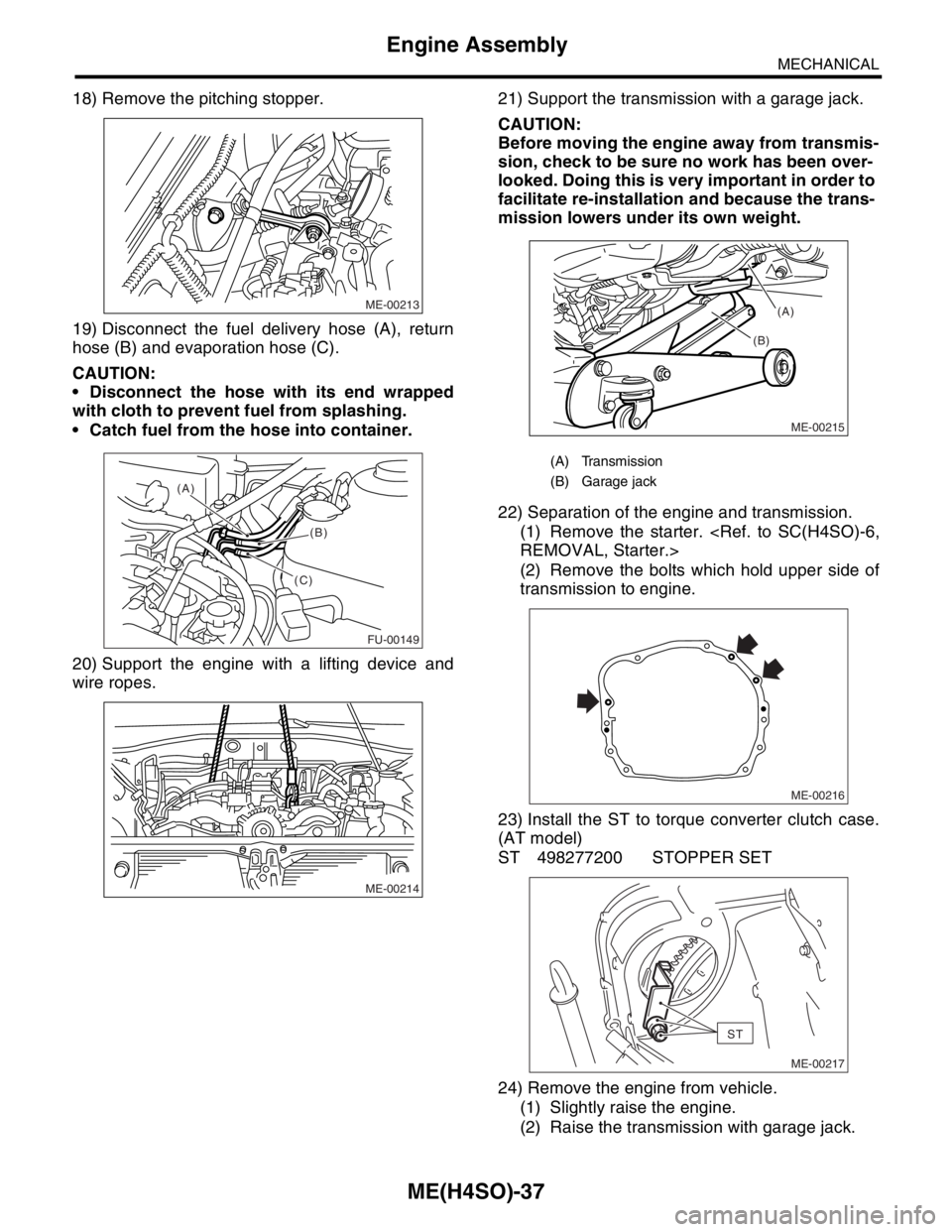
18) Remove the pitching stopper.
19) Disconnect the fuel delivery hose (A), return
hose (B) and evaporation hose (C).
CAUTION:
Disconnect the hose with its end wrapped
with cloth to prevent fuel from splashing.
Catch fuel from the hose into container.
20) Support the engine with a lifting device and
wire ropes.21) Support the transmission with a garage jack.
CAUTION:
Before moving the engine away from transmis-
sion, check to be sure no work has been over-
looked. Doing this is very important in order to
facilitate re-installation and because the trans-
mission lowers under its own weight.
22) Separation of the engine and transmission.
(1) Remove the starter.
(2) Remove the bolts which hold upper side of
transmission to engine.
23) Install the ST to torque converter clutch case.
(AT model)
ST 498277200 STOPPER SET
24) Remove the engine from vehicle.
(1) Slightly raise the engine.
(2) Raise the transmission with garage jack.
ME-00213
FU-00149
(A)
(B)
(C)
ME-00214
(A) Transmission
(B) Garage jack
ME-00215
(B)(A)
ME-00216
ST
ME-00217
Page 909 of 2870
ME(H4SO)-40
MECHANICAL
Engine Assembly
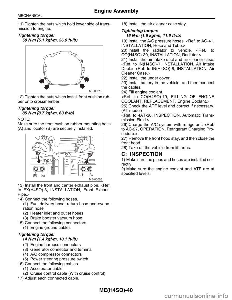
11) Tighten the nuts which hold lower side of trans-
mission to engine.
Tightening torque:
50 N
⋅m (5.1 kgf-m, 36.9 ft-lb)
12) Tighten the nuts which install front cushion rub-
ber onto crossmember.
Tightening torque:
85 N
⋅m (8.7 kgf-m, 63 ft-lb)
NOTE:
Make sure the front cushion rubber mounting bolts
(A) and locator (B) are securely installed.
13) Install the front and center exhaust pipe.
Pipe.>
14) Connect the following hoses.
(1) Fuel delivery hose, return hose and evapo-
ration hose
(2) Heater inlet and outlet hoses
(3) Brake booster vacuum hose
15) Connect the following connectors.
(1) Engine ground cables
Tightening torque:
14 N
⋅m (1.4 kgf-m, 10.1 ft-lb)
(2) Engine harness connectors
(3) Generator connector and terminal
(4) A/C compressor connectors
(5) Power steering pressure switch
16) Connect the following cables.
(1) Accelerator cable
(2) Cruise control cable (With cruise control)
17) Adjust each connected cable.18) Install the air cleaner case stay.
Tightening torque:
16 N
⋅m (1.6 kgf-m, 11.6 ft-lb)
19) Install the A/C pressure hoses.
20) Install the radiator to vehicle.
21) Install the air intake duct and air cleaner case.
22) Install the under cover.
23) Install battery in the vehicle, and then connect
the cables.
24) Fill engine coolant.
25) Check the ATF level and correct if necessary.
(AT model)
26) Charge the A/C system with refrigerant.
cedure.>
27) Remove the front hood stay, and then close the
front hood.
28) Take off the vehicle from lift arms.
C: INSPECTION
1) Make sure the pipes and hoses are installed cor-
rectly.
2) Make sure the engine coolant and ATF are at
specified levels.
ME-00219
ME-00056
(A)
(A)(B)
(B)
Page 922 of 2870
FUJI HEAVY INDUSTRIES LTD. G8080GE2
2004 FORESTER SERVICE MANUAL QUICK REFERENCE INDEX
ENGINE SECTION 1
This service manual has been prepared
to provide SUBARU service personnel
with the necessary information and data
for the correct maintenance and repair
of SUBARU vehicles.
This manual includes the procedures
for maintenance, disassembling, reas-
sembling, inspection and adjustment of
components and diagnostics for guid-
ance of experienced mechanics.
Please peruse and utilize this manual
fully to ensure complete repair work for
satisfying our customers by keeping
their vehicle in optimum condition.
When replacement of parts during
repair work is needed, be sure to use
SUBARU genuine parts.
All information, illustration and specifi-
cations contained in this manual are
based on the latest product information
available at the time of publication
approval.FUEL INJECTION (FUEL SYSTEM) FU(H4SO)
EMISSION CONTROL
(AUX. EMISSION CONTROL DEVICE)EC(H4SO)
INTAKE (INDUCTION) IN(H4SO)
MECHANICAL ME(H4SO)
EXHAUST EX(H4SO)
COOLING CO(H4SO)
LUBRICATION LU(H4SO)
SPEED CONTROL SYSTEM SP(H4SO)
IGNITION IG(H4SO)
STARTING/CHARGING SYSTEM SC(H4SO)
ENGINE (DIAGNOSTIC) EN(H4SO)
Page 923 of 2870

MECHANICAL
ME(H4SO)
Page
1. General Description ....................................................................................2
2. Compression .............................................................................................25
3. Idle Speed .................................................................................................26
4. Ignition Timing ...........................................................................................27
5. Intake Manifold Vacuum............................................................................28
6. Engine Oil Pressure ..................................................................................29
7. Fuel Pressure ............................................................................................30
8. Valve Clearance ........................................................................................31
9. Engine Assembly ......................................................................................34
10. Engine Mounting .......................................................................................41
11. Preparation for Overhaul ...........................................................................42
12. V-belt .........................................................................................................43
13. Crank Pulley ..............................................................................................45
14. Timing Belt Cover......................................................................................47
15. Timing Belt ................................................................................................48
16. Cam Sprocket ...........................................................................................53
17. Crank Sprocket .........................................................................................55
18. Valve Rocker Assembly ............................................................................56
19. Camshaft ...................................................................................................58
20. Cylinder Head ...........................................................................................62
21. Cylinder Block ...........................................................................................69
22. Engine Trouble in General ........................................................................91
23. Engine Noise .............................................................................................96
Page 962 of 2870

ME(H4SO)-91
MECHANICAL
Engine Trouble in General
22.Engine Trouble in General
A: INSPECTION
NOTE:
“RANK” shown in the chart refer to the possibility of reason for the trouble in order (“Very often” to “Rarely”)
A — Very often
B — Sometimes
C — Rarely
TROUBLE PROBLEM PARTS, ETC. POSSIBLE CAUSE RANK
1. Engine will not start.
1) Starter does not turn. Starter Defective battery-to-starter harness B
Defective starter switch C
Defective inhibitor switch or neutral switch C
Defective starter B
Battery Poor terminal connection A
Run-down battery A
Defective charging system B
Friction Seizure of crankshaft and connecting rod bearing C
Seized camshaft C
Seized or stuck piston and cylinder C
2) Initial combustion does
not occur. Starter Defective starter C
Engine control system
Fuel line Defective fuel pump and relay A
Lack of or insufficient fuel B
Belt Defective B
Defective timing B
Compression Incorrect valve clearance C
Loosened spark plugs or defective gasket C
Loosened cylinder head bolts or defective gasket C
Improper valve seating C
Defective valve stem C
Worn or broken valve spring B
Worn or stuck piston rings, cylinder and piston C
Incorrect valve timing B
Improper engine oil (low viscosity) B
3) Initial combustion occurs. Engine control system
Intake system Defective intake manifold gasket B
Defective throttle body gasket B
Fuel line Defective fuel pump and relay C
Clogged fuel line C
Lack of or insufficient fuel B
Belt Defective B
Defective timing B
Compression Incorrect valve clearance C
Loosened spark plugs or defective gasket C
Loosened cylinder head bolts or defective gasket C
Improper valve seating C
Defective valve stem C
Worn or broken valve spring B
Worn or stuck piston rings, cylinder and piston C
Incorrect valve timing B
Improper engine oil (low viscosity) B