2004 SUBARU FORESTER maintenance
[x] Cancel search: maintenancePage 756 of 2870
PM-19
PERIODIC MAINTENANCE SERVICE
Air Cleaner Element
10.Air Cleaner Element
A: REMOVAL
1. NON-TURBO MODEL
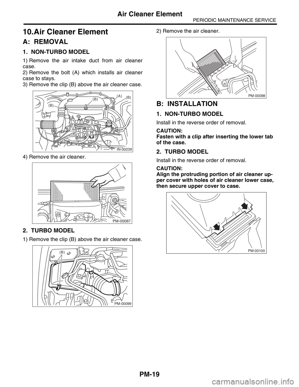
1) Remove the air intake duct from air cleaner
case.
2) Remove the bolt (A) which installs air cleaner
case to stays.
3) Remove the clip (B) above the air cleaner case.
4) Remove the air cleaner.
2. TURBO MODEL
1) Remove the clip (B) above the air cleaner case.2) Remove the air cleaner.
B: INSTALLATION
1. NON-TURBO MODEL
Install in the reverse order of removal.
CAUTION:
Fasten with a clip after inserting the lower tab
of the case.
2. TURBO MODEL
Install in the reverse order of removal.
CAUTION:
Align the protruding portion of air cleaner up-
per cover with holes of air cleaner lower case,
then secure upper cover to case.
IN-00239
(B)(B)(B)
(A)
PM-00087
(B)
PM-00099
PM-00098
PM-00100
Page 757 of 2870
PM-20
PERIODIC MAINTENANCE SERVICE
Cooling System
11.Cooling System
A: INSPECTION
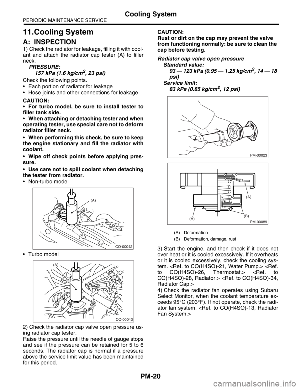
1) Check the radiator for leakage, filling it with cool-
ant and attach the radiator cap tester (A) to filler
neck.
PRESSURE:
157 kPa (1.6 kg/cm
2, 23 psi)
Check the following points.
Each portion of radiator for leakage
Hose joints and other connections for leakage
CAUTION:
For turbo model, be sure to install tester to
filler tank side.
When attaching or detaching tester and when
operating tester, use special care not to deform
radiator filler neck.
When performing this check, be sure to keep
the engine stationary and fill the radiator with
coolant.
Wipe off check points before applying pres-
sure.
Use care not to spill coolant when detaching
the tester from radiator.
Non-turbo model
Turbo model
2) Check the radiator cap valve open pressure us-
ing radiator cap tester.
Raise the pressure until the needle of gauge stops
and see if the pressure can be retained for 5 to 6
seconds. The radiator cap is normal if a pressure
above the service limit value has been maintained
for this period.CAUTION:
Rust or dirt on the cap may prevent the valve
from functioning normally: be sure to clean the
cap before testing.
Radiator cap valve open pressure
Standard value:
93 — 123 kPa (0.95 — 1.25 kg/cm2, 14 — 18
psi)
Service limit:
83 kPa (0.85 kg/cm
2, 12 psi)
3) Start the engine, and then check if it does not
over heat or it is cooled excessively. If it overheats
or it is cooled excessively, check the cooling sys-
tem.
4) Check the radiator fan operates using Subaru
Select Monitor, when the coolant temperature ex-
ceeds 95°C (203°F). If not operate, check the radi-
ator fan system.
CO-00042
(A)
CO-00043
(A)
(A) Deformation
(B) Deformation, damage, rust
PM-00023
PM-00089
(B)
(A)(A)
Page 758 of 2870
PM-21
PERIODIC MAINTENANCE SERVICE
Engine Coolant
12.Engine Coolant
A: REPLACEMENT
1. REPLACEMENT OF ENGINE COOLANT
WARNING:
The radiator is of the pressurized type. Do not
attempt to open the radiator cap immediately
after the engine has been stopped.
1) Lift-up the vehicle.
2) Remove the under cover.
3) Place a container under drain pipe.
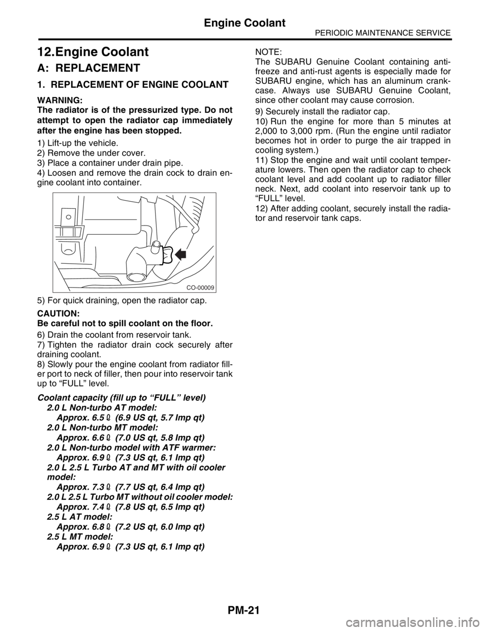
4) Loosen and remove the drain cock to drain en-
gine coolant into container.
5) For quick draining, open the radiator cap.
CAUTION:
Be careful not to spill coolant on the floor.
6) Drain the coolant from reservoir tank.
7) Tighten the radiator drain cock securely after
draining coolant.
8) Slowly pour the engine coolant from radiator fill-
er port to neck of filler, then pour into reservoir tank
up to “FULL” level.
Coolant capacity (fill up to “FULL” level)
2.0 L Non-turbo AT model:
Approx. 6.52 (6.9 US qt, 5.7 Imp qt)
2.0 L Non-turbo MT model:
Approx. 6.62 (7.0 US qt, 5.8 Imp qt)
2.0 L Non-turbo model with ATF warmer:
Approx. 6.92 (7.3 US qt, 6.1 Imp qt)
2.0 L 2.5 L Turbo AT and MT with oil cooler
model:
Approx. 7.32 (7.7 US qt, 6.4 Imp qt)
2.0 L 2.5 L Turbo MT without oil cooler model:
Approx. 7.42 (7.8 US qt, 6.5 Imp qt)
2.5 L AT model:
Approx. 6.82 (7.2 US qt, 6.0 Imp qt)
2.5 L MT model:
Approx. 6.92 (7.3 US qt, 6.1 Imp qt)NOTE:
The SUBARU Genuine Coolant containing anti-
freeze and anti-rust agents is especially made for
SUBARU engine, which has an aluminum crank-
case. Always use SUBARU Genuine Coolant,
since other coolant may cause corrosion.
9) Securely install the radiator cap.
10) Run the engine for more than 5 minutes at
2,000 to 3,000 rpm. (Run the engine until radiator
becomes hot in order to purge the air trapped in
cooling system.)
11) Stop the engine and wait until coolant temper-
ature lowers. Then open the radiator cap to check
coolant level and add coolant up to radiator filler
neck. Next, add coolant into reservoir tank up to
“FULL” level.
12) After adding coolant, securely install the radia-
tor and reservoir tank caps.
CO-00009
Page 759 of 2870
PM-22
PERIODIC MAINTENANCE SERVICE
Engine Coolant
2. RELATIONSHIP OF SUBARU COOLANT
CONCENTRATION AND FREEZING TEM-
PERATURE
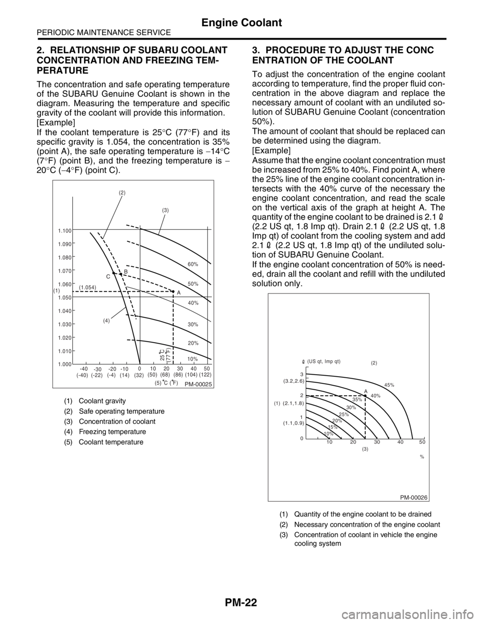
The concentration and safe operating temperature
of the SUBARU Genuine Coolant is shown in the
diagram. Measuring the temperature and specific
gravity of the coolant will provide this information.
[Example]
If the coolant temperature is 25°C (77°F) and its
specific gravity is 1.054, the concentration is 35%
(point A), the safe operating temperature is −14°C
(7°F) (point B), and the freezing temperature is −
20°C (−4°F) (point C).
3. PROCEDURE TO ADJUST THE CONC
ENTRATION OF THE COOLANT
To adjust the concentration of the engine coolant
according to temperature, find the proper fluid con-
centration in the above diagram and replace the
necessary amount of coolant with an undiluted so-
lution of SUBARU Genuine Coolant (concentration
50%).
The amount of coolant that should be replaced can
be determined using the diagram.
[Example]
Assume that the engine coolant concentration must
be increased from 25% to 40%. Find point A, where
the 25% line of the engine coolant concentration in-
tersects with the 40% curve of the necessary the
engine coolant concentration, and read the scale
on the vertical axis of the graph at height A. The
quantity of the engine coolant to be drained is 2.12
(2.2 US qt, 1.8 Imp qt). Drain 2.12 (2.2 US qt, 1.8
Imp qt) of coolant from the cooling system and add
2.12 (2.2 US qt, 1.8 Imp qt) of the undiluted solu-
tion of SUBARU Genuine Coolant.
If the engine coolant concentration of 50% is need-
ed, drain all the coolant and refill with the undiluted
solution only.
(1) Coolant gravity
(2) Safe operating temperature
(3) Concentration of coolant
(4) Freezing temperature
(5) Coolant temperature
PM-00025
60%
(1.054)
1.000 1.010 1.020
1.030
1.040
1.050
1.060
1.070 1.080 1.090
1.100
(5) (4)(3) (2)
(1)B
A C
-40
(-40) (-22)(-4)
(14)(32)(50) (68) (86)
( F)(104) (122) -30-20 -1001020304050
(77 F)
50%
40%
30%
20%
25 C10%
C
(1) Quantity of the engine coolant to be drained
(2) Necessary concentration of the engine coolant
(3) Concentration of coolant in vehicle the engine
cooling system
PM-00026
10 0 12 3
(1.1,0.9) (2.1,1.8)(3.2,2.6)
10%15%25%
20%30%35%40%45%
A
20 30 40 50
% (3)(2)
(1)(US qt, Imp qt)
Page 760 of 2870
PM-23
PERIODIC MAINTENANCE SERVICE
Clutch System
13.Clutch System
A: INSPECTION AND ADJUSTMENT
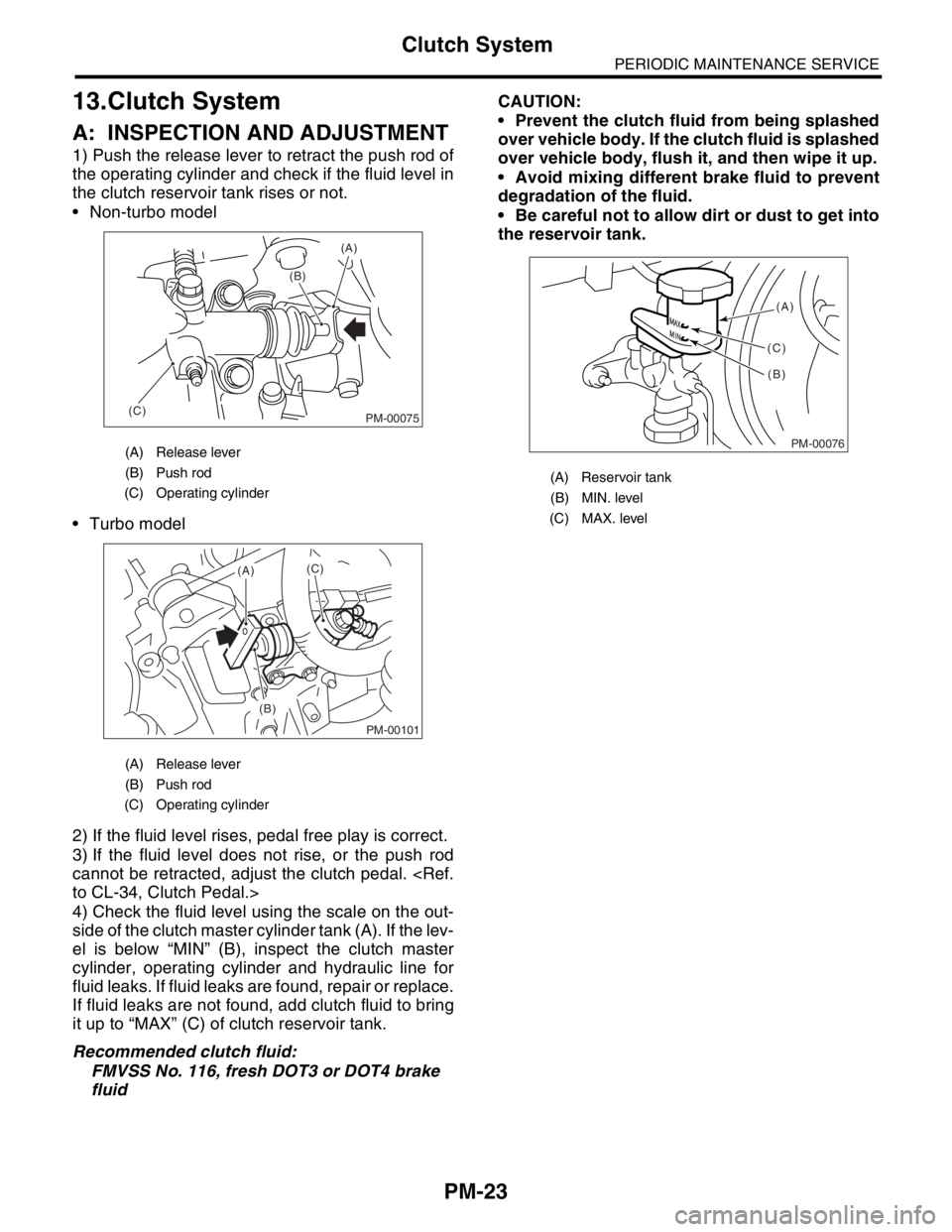
1) Push the release lever to retract the push rod of
the operating cylinder and check if the fluid level in
the clutch reservoir tank rises or not.
Non-turbo model
Turbo model
2) If the fluid level rises, pedal free play is correct.
3) If the fluid level does not rise, or the push rod
cannot be retracted, adjust the clutch pedal.
4) Check the fluid level using the scale on the out-
side of the clutch master cylinder tank (A). If the lev-
el is below “MIN” (B), inspect the clutch master
cylinder, operating cylinder and hydraulic line for
fluid leaks. If fluid leaks are found, repair or replace.
If fluid leaks are not found, add clutch fluid to bring
it up to “MAX” (C) of clutch reservoir tank.
Recommended clutch fluid:
FMVSS No. 116, fresh DOT3 or DOT4 brake
fluidCAUTION:
Prevent the clutch fluid from being splashed
over vehicle body. If the clutch fluid is splashed
over vehicle body, flush it, and then wipe it up.
Avoid mixing different brake fluid to prevent
degradation of the fluid.
Be careful not to allow dirt or dust to get into
the reservoir tank.
(A) Release lever
(B) Push rod
(C) Operating cylinder
(A) Release lever
(B) Push rod
(C) Operating cylinder
PM-00075
(A)
(C)(B)
PM-00101
(A)
(B)(C)
(A) Reservoir tank
(B) MIN. level
(C) MAX. level
PM-00076
(A)
(B) (C)
Page 761 of 2870
PM-24
PERIODIC MAINTENANCE SERVICE
Transmission Gear Oil
14.Transmission Gear Oil
A: REPLACEMENT
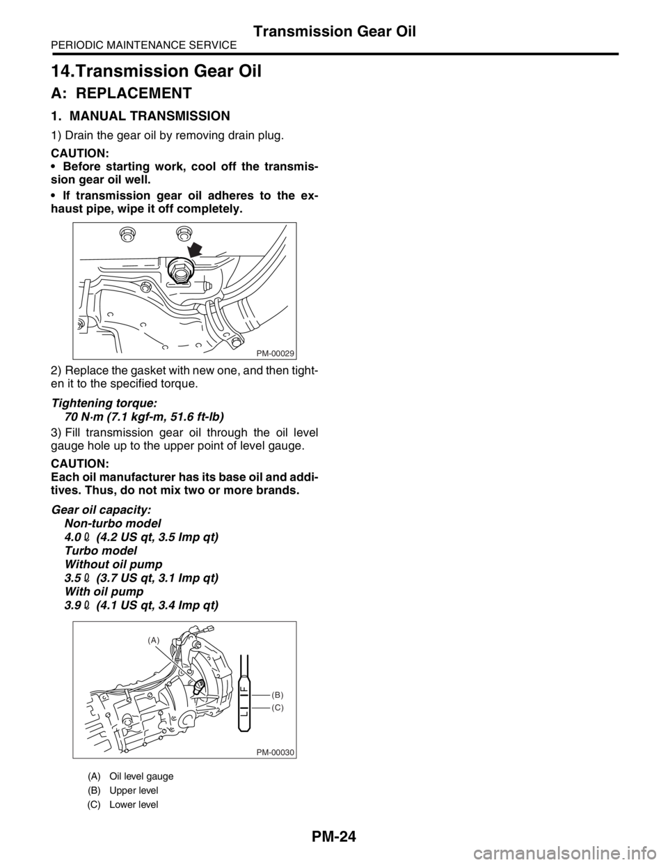
1. MANUAL TRANSMISSION
1) Drain the gear oil by removing drain plug.
CAUTION:
Before starting work, cool off the transmis-
sion gear oil well.
If transmission gear oil adheres to the ex-
haust pipe, wipe it off completely.
2) Replace the gasket with new one, and then tight-
en it to the specified torque.
Tightening torque:
70 N·m (7.1 kgf-m, 51.6 ft-lb)
3) Fill transmission gear oil through the oil level
gauge hole up to the upper point of level gauge.
CAUTION:
Each oil manufacturer has its base oil and addi-
tives. Thus, do not mix two or more brands.
Gear oil capacity:
Non-turbo model
4.02 (4.2 US qt, 3.5 Imp qt)
Turbo model
Without oil pump
3.52 (3.7 US qt, 3.1 Imp qt)
With oil pump
3.92 (4.1 US qt, 3.4 Imp qt)
(A) Oil level gauge
(B) Upper level
(C) Lower level
PM-00029
PM-00030
(B)
(C) (A)
Page 762 of 2870

PM-25
PERIODIC MAINTENANCE SERVICE
Hill-holder System
15.Hill-holder System
A: INSPECTION AND ADJUSTMENT
1) Confirm the stopping and starting performance
by activating the hill-holder on an uphill road of 3°
or higher inclination.
(1) When the vehicle does not stop;
Tighten the adjusting nut of PHV cable.
(2) When the vehicle does not start properly;
A; When the hill-holder is released later than en-
gagement of clutch (engine tends to stall): Loos-
en the adjusting nut gradually until smooth
starting is enabled.
B; When the hill-holder is released earlier than
engagement to clutch (vehicle slips down slight-
ly): Tighten the adjusting nut so that hill-holder is
released later than engagement of clutch (status
in A). Then make adjustment the same as in A.
CAUTION:
Whenever turning the adjusting nut, hold the
inner cable with pliers to prevent it from turn-
ing.
Replace the pressure hold valve (PHV) or
PHV cable with a new one, if they are defective
and/or damaged.
(A) Lock nut
(B) Adjusting nut
(C) Pressure hold valve
(C) (B)
(A)
PM-00077
Page 763 of 2870
PM-26
PERIODIC MAINTENANCE SERVICE
ATF
16.ATF
A: INSPECTION
CAUTION:
The level of ATF varies with fluid temperature.
Pay attention to the fluid temperature when
checking ATF level.
1) Raise the ATF temperature by driving a distance
of 5 to 10 km (3 to 6 miles). Otherwise, idle the en-
gine to raise ATF temperature to 70 — 80°C (158
— 176°F) on Subaru Select Monitor.
TION, Subaru Select Monitor.>
2) Make sure the vehicle is level.
3) After selecting all positions (P, R, N, D, 3, 2, 1),
set the select lever in “P” range. Measure the ATF
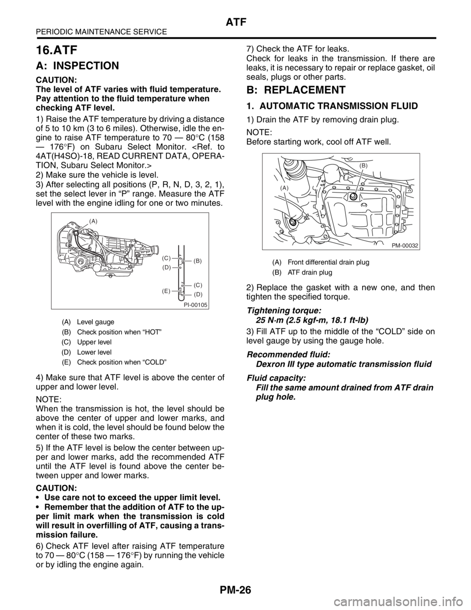
level with the engine idling for one or two minutes.
4) Make sure that ATF level is above the center of
upper and lower level.
NOTE:
When the transmission is hot, the level should be
above the center of upper and lower marks, and
when it is cold, the level should be found below the
center of these two marks.
5) If the ATF level is below the center between up-
per and lower marks, add the recommended ATF
until the ATF level is found above the center be-
tween upper and lower marks.
CAUTION:
Use care not to exceed the upper limit level.
Remember that the addition of ATF to the up-
per limit mark when the transmission is cold
will result in overfilling of ATF, causing a trans-
mission failure.
6) Check ATF level after raising ATF temperature
to 70 — 80°C (158 — 176°F) by running the vehicle
or by idling the engine again.7) Check the ATF for leaks.
Check for leaks in the transmission. If there are
leaks, it is necessary to repair or replace gasket, oil
seals, plugs or other parts.
B: REPLACEMENT
1. AUTOMATIC TRANSMISSION FLUID
1) Drain the ATF by removing drain plug.
NOTE:
Before starting work, cool off ATF well.
2) Replace the gasket with a new one, and then
tighten the specified torque.
Tightening torque:
25 N·m (2.5 kgf-m, 18.1 ft-lb)
3) Fill ATF up to the middle of the “COLD” side on
level gauge by using the gauge hole.
Recommended fluid:
Dexron III type automatic transmission fluid
Fluid capacity:
Fill the same amount drained from ATF drain
plug hole.
(A) Level gauge
(B) Check position when “HOT”
(C) Upper level
(D) Lower level
(E) Check position when “COLD”
PI-00105
COLD
LFHOT LF
(A)
(C)
(D)
(C)
(D)
(E)
(B)(A) Front differential drain plug
(B) ATF drain plug
PM-00032
(B)
(A)