2004 SUBARU FORESTER maintenance
[x] Cancel search: maintenancePage 772 of 2870
PM-35
PERIODIC MAINTENANCE SERVICE
Brake Linings and Drums
2) Check the disk rotor for wear, dents or other
damage. If the inside surface of disk rotor is
streaked, correct the surface with emery cloth
(#200 or more). If it is unevenly worn or tapered,
correct or replace it.
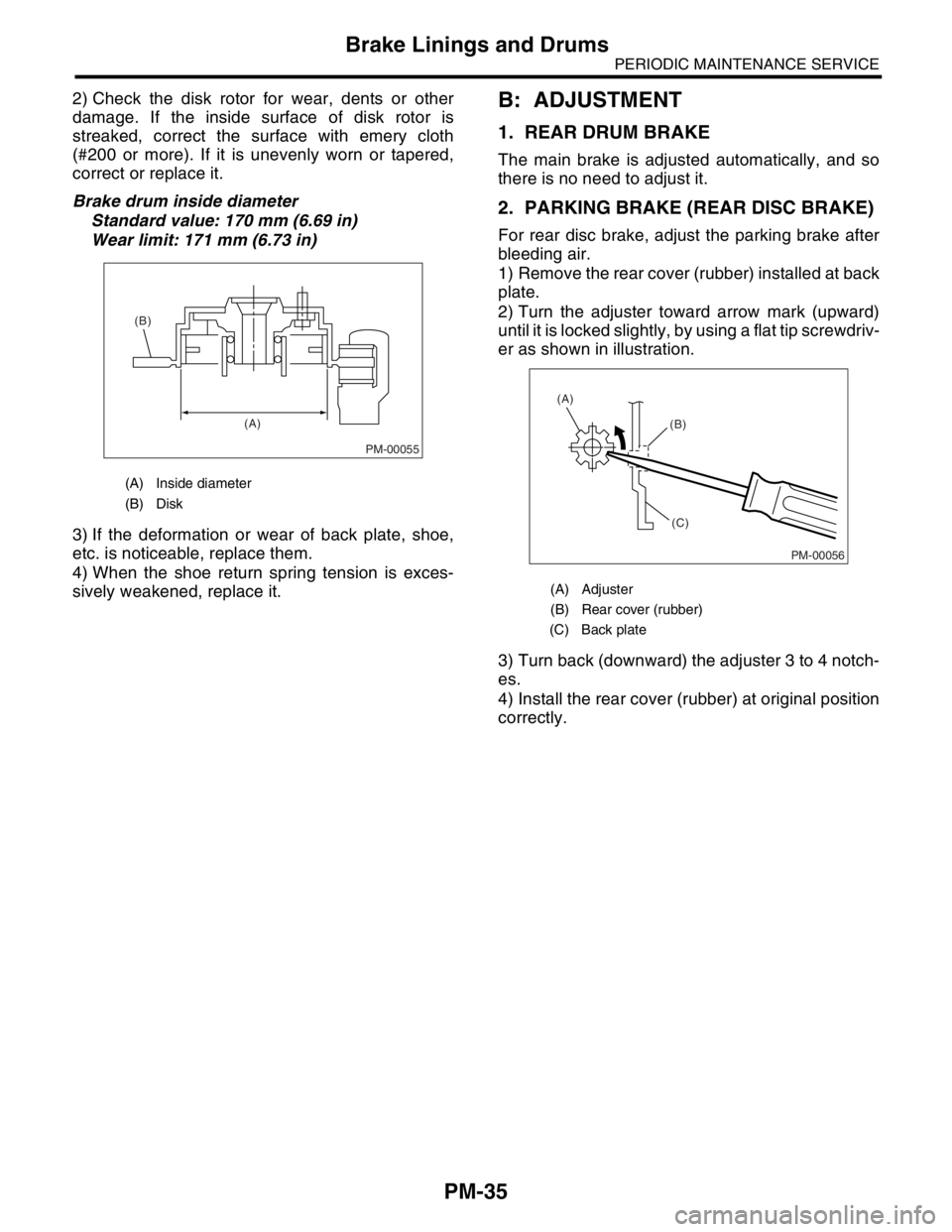
Brake drum inside diameter
Standard value: 170 mm (6.69 in)
Wear limit: 171 mm (6.73 in)
3) If the deformation or wear of back plate, shoe,
etc. is noticeable, replace them.
4) When the shoe return spring tension is exces-
sively weakened, replace it.B: ADJUSTMENT
1. REAR DRUM BRAKE
The main brake is adjusted automatically, and so
there is no need to adjust it.
2. PARKING BRAKE (REAR DISC BRAKE)
For rear disc brake, adjust the parking brake after
bleeding air.
1) Remove the rear cover (rubber) installed at back
plate.
2) Turn the adjuster toward arrow mark (upward)
until it is locked slightly, by using a flat tip screwdriv-
er as shown in illustration.
3) Turn back (downward) the adjuster 3 to 4 notch-
es.
4) Install the rear cover (rubber) at original position
correctly.
(A) Inside diameter
(B) Disk
PM-00055
(A) (B)
(A) Adjuster
(B) Rear cover (rubber)
(C) Back plate
PM-00056
(B)
(C) (A)
Page 773 of 2870
PM-36
PERIODIC MAINTENANCE SERVICE
Suspension
22.Suspension
A: INSPECTION
1. SUSPENSION BALL JOINT
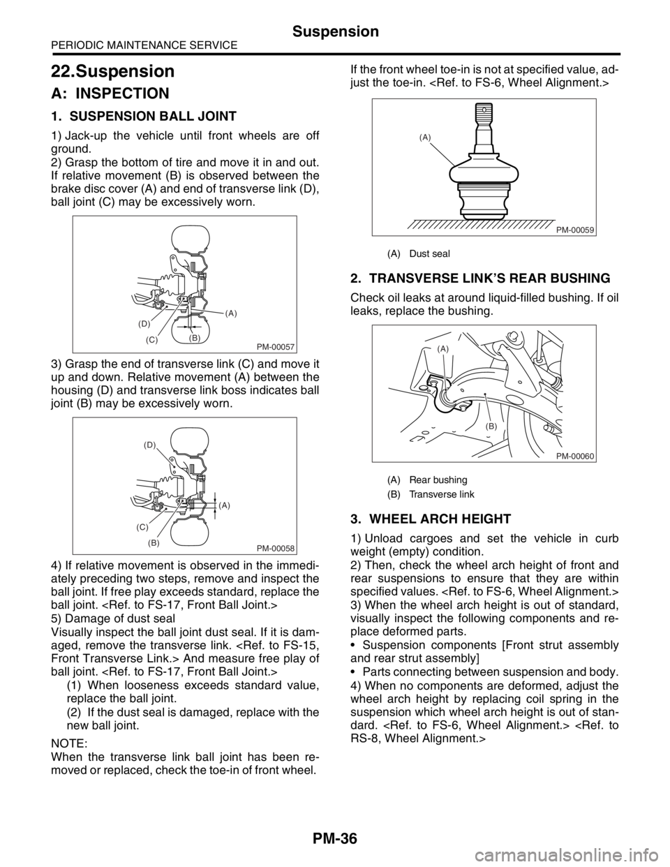
1) Jack-up the vehicle until front wheels are off
ground.
2) Grasp the bottom of tire and move it in and out.
If relative movement (B) is observed between the
brake disc cover (A) and end of transverse link (D),
ball joint (C) may be excessively worn.
3) Grasp the end of transverse link (C) and move it
up and down. Relative movement (A) between the
housing (D) and transverse link boss indicates ball
joint (B) may be excessively worn.
4) If relative movement is observed in the immedi-
ately preceding two steps, remove and inspect the
ball joint. If free play exceeds standard, replace the
ball joint.
5) Damage of dust seal
Visually inspect the ball joint dust seal. If it is dam-
aged, remove the transverse link.
ball joint.
(1) When looseness exceeds standard value,
replace the ball joint.
(2) If the dust seal is damaged, replace with the
new ball joint.
NOTE:
When the transverse link ball joint has been re-
moved or replaced, check the toe-in of front wheel. If the front wheel toe-in is not at specified value, ad-
just the toe-in.
2. TRANSVERSE LINK’S REAR BUSHING
Check oil leaks at around liquid-filled bushing. If oil
leaks, replace the bushing.
3. WHEEL ARCH HEIGHT
1) Unload cargoes and set the vehicle in curb
weight (empty) condition.
2) Then, check the wheel arch height of front and
rear suspensions to ensure that they are within
specified values.
3) When the wheel arch height is out of standard,
visually inspect the following components and re-
place deformed parts.
Suspension components [Front strut assembly
and rear strut assembly]
Parts connecting between suspension and body.
4) When no components are deformed, adjust the
wheel arch height by replacing coil spring in the
suspension which wheel arch height is out of stan-
dard.
PM-00057
(A)
(B)
(C) (D)
PM-00058
(A)
(B) (C)(D)
(A) Dust seal
(A) Rear bushing
(B) Transverse link
PM-00059
(A)
PM-00060
(A)
(B)
Page 774 of 2870

PM-37
PERIODIC MAINTENANCE SERVICE
Suspension
4. WHEEL ALIGNMENT OF FRONT SUS-
PENSION
1) Check the alignment of front suspension to en-
sure that following items conform to standard val-
ues.
Toe-in
Camber angle
Caster angle
Steering angle
2) When the caster angle does not conform to ref-
erence, visually inspect the following components
and replace deformed parts.
Suspension components [Strut assembly, cross-
member, transverse link, etc.]
Body parts to which suspensions are installed.
3) When the toe-in and camber are out of standard
value, adjust them so that they conform to respec-
tive service standard.
ment.>
4) When the right-and-left turning angles of tire are
out of standard, adjust to standard value.
Alignment.>
5. WHEEL ALIGNMENT OF REAR SUS-
PENSION
1) Check the alignment of rear suspension to en-
sure that following items are within standard val-
ues.
Toe-in
Camber angle
Thrust angle
2) When the camber angle does not conform to ref-
erence, visually inspect parts listed below. If defor-
mation is observed, replace the damaged parts.
Suspension components [Shock absorber, front
lateral links, rear lateral links, trailing link, etc.]
Body parts to which suspensions are installed.
3) When the toe-in and thrust angle are out of stan-
dard value, adjust them so that they conform to re-
spective service standard.
ment.>
6. OIL LEAKAGE OF STRUT
Visually inspect the front strut and rear strut for oil
leakage as instructed. If oil leakage reaches under
spring seat lower portion, replace the front strut and
rear strut.
7. TIGHTNESS OF BOLTS AND NUTS
Check the bolts and nuts shown in the figure for
looseness. Retighten the bolts and nuts to speci-
fied torque. If the self-lock nuts and bolts are re-
moved, replace them with new ones.
Front suspension:
Rear suspension:
8. DAMAGE TO SUSPENSION PARTS
Check the following parts and the fastening portion
of the vehicle body for deformation or excessive
rusting which impairs the suspension. Remove the
contaminations on spring seat lower portion with
care because dirt, sand, etc. tend to accumulate on
it. If necessary, replace the damaged parts with
new ones. If minor rust formation, pitting, etc. are
noted, remove the rust and apply remedial anti-cor-
rosion measures.
Front suspension
Transverse link
Crossmember
Strut
Rear suspension
Crossmember
Lateral links
Trailing link
Strut
In the district where salt is sprayed to melt snow
on a road in winter, check suspension parts for
damage caused by rust every 12 months after
lapse of 60 months. Take rust prevention measure
as required.
Page 775 of 2870
PM-38
PERIODIC MAINTENANCE SERVICE
Wheel Bearing
23.Wheel Bearing
A: INSPECTION
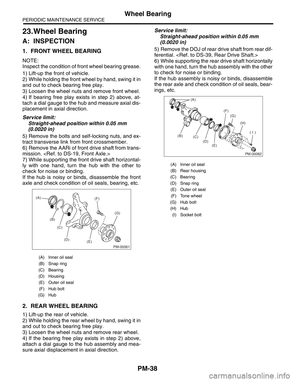
1. FRONT WHEEL BEARING
NOTE:
Inspect the condition of front wheel bearing grease.
1) Lift-up the front of vehicle.
2) While holding the front wheel by hand, swing it in
and out to check bearing free play.
3) Loosen the wheel nuts and remove front wheel.
4) If bearing free play exists in step 2) above, at-
tach a dial gauge to the hub and measure axial dis-
placement in axial direction.
Service limit:
Straight-ahead position within 0.05 mm
(0.0020 in)
5) Remove the bolts and self-locking nuts, and ex-
tract transverse link from front crossmember.
6) Remove the AARi of front drive shaft from trans-
mission.
7) While supporting the front drive shaft horizontal-
ly with one hand, turn the hub with the other to
check for noise or binding.
If the hub is noisy or binds, disassemble the front
axle and check condition of oil seals, bearing, etc.
2. REAR WHEEL BEARING
1) Lift-up the rear of vehicle.
2) While holding the rear wheel by hand, swing it in
and out to check bearing free play.
3) Loosen the wheel nuts and remove rear wheel.
4) If the bearing free play exists in step 2) above,
attach a dial gauge to the hub assembly and mea-
sure axial displacement in axial direction.Service limit:
Straight-ahead position within 0.05 mm
(0.0020 in)
5) Remove the DOJ of rear drive shaft from rear dif-
ferential.
6) While supporting the rear drive shaft horizontally
with one hand, turn the hub assembly with the other
to check for noise or binding.
If the hub assembly is noisy or binds, disassemble
the rear axle and check condition of oil seals, bear-
ings, etc.
(A) Inner oil seal
(B) Snap ring
(C) Bearing
(D) Housing
(E) Outer oil seal
(F) Hub bolt
(G) Hub
PM-00061
(A)
(B)
(C)
(D)
(E)(G) (F)
(A) Inner oil seal
(B) Rear housing
(C) Bearing
(D) Snap ring
(E) Outer oil seal
(F) Tone wheel
(G) Hub bolt
(H) Hub
(I) Socket bolt
PM-00062
(A)
(B)
(C)
(D)
(E)(G)
(H)
( I ) (F)
Page 776 of 2870
PM-39
PERIODIC MAINTENANCE SERVICE
Axle Boots & Joints
24.Axle Boots & Joints
A: INSPECTION
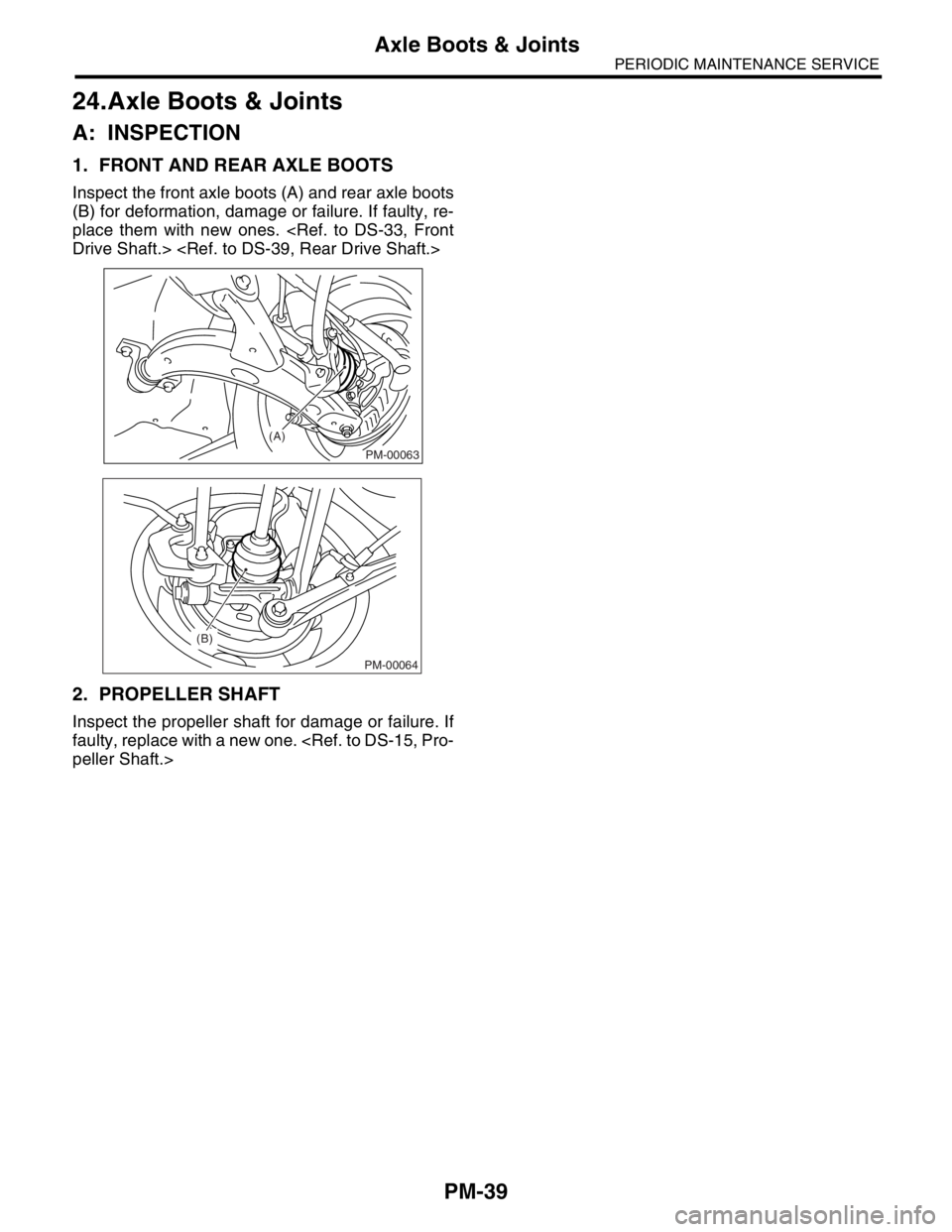
1. FRONT AND REAR AXLE BOOTS
Inspect the front axle boots (A) and rear axle boots
(B) for deformation, damage or failure. If faulty, re-
place them with new ones.
2. PROPELLER SHAFT
Inspect the propeller shaft for damage or failure. If
faulty, replace with a new one.
(A)
PM-00063
(B)
PM-00064
Page 777 of 2870
PM-40
PERIODIC MAINTENANCE SERVICE
Tire Rotation
25.Tire Rotation
A: INSPECTION
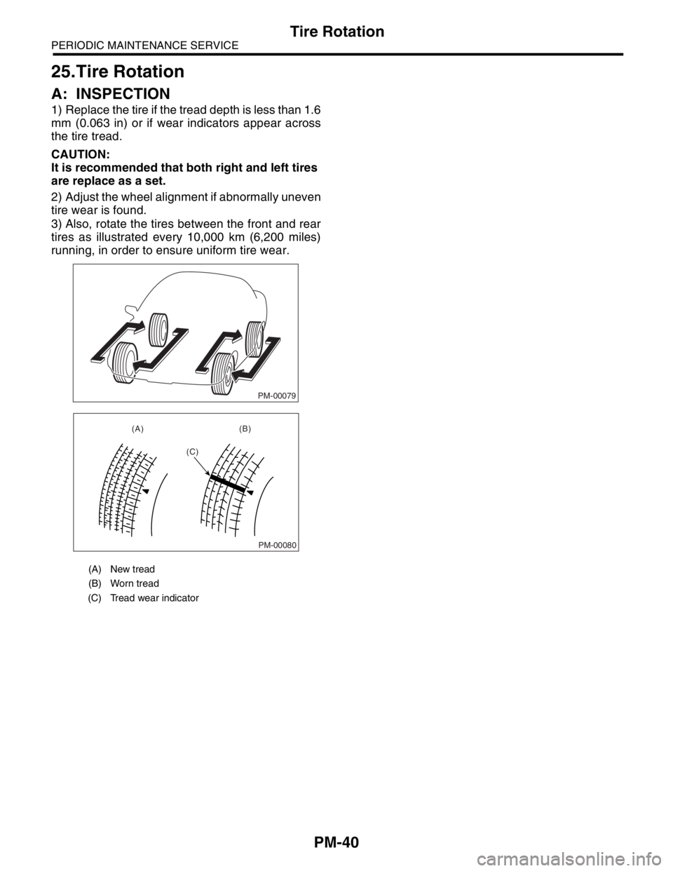
1) Replace the tire if the tread depth is less than 1.6
mm (0.063 in) or if wear indicators appear across
the tire tread.
CAUTION:
It is recommended that both right and left tires
are replace as a set.
2) Adjust the wheel alignment if abnormally uneven
tire wear is found.
3) Also, rotate the tires between the front and rear
tires as illustrated every 10,000 km (6,200 miles)
running, in order to ensure uniform tire wear.
(A) New tread
(B) Worn tread
(C) Tread wear indicator
PM-00079
PM-00080
(A) (B)
(C)
Page 778 of 2870
PM-41
PERIODIC MAINTENANCE SERVICE
Steering System (Power Steering)
26.Steering System (Power
Steering)
A: INSPECTION
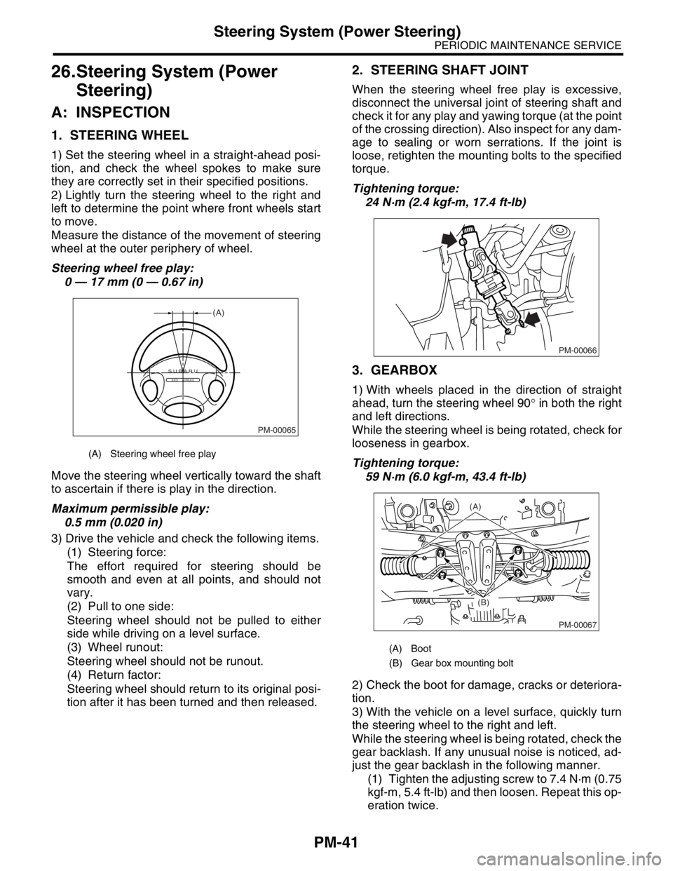
1. STEERING WHEEL
1) Set the steering wheel in a straight-ahead posi-
tion, and check the wheel spokes to make sure
they are correctly set in their specified positions.
2) Lightly turn the steering wheel to the right and
left to determine the point where front wheels start
to move.
Measure the distance of the movement of steering
wheel at the outer periphery of wheel.
Steering wheel free play:
0 — 17 mm (0 — 0.67 in)
Move the steering wheel vertically toward the shaft
to ascertain if there is play in the direction.
Maximum permissible play:
0.5 mm (0.020 in)
3) Drive the vehicle and check the following items.
(1) Steering force:
The effort required for steering should be
smooth and even at all points, and should not
vary.
(2) Pull to one side:
Steering wheel should not be pulled to either
side while driving on a level surface.
(3) Wheel runout:
Steering wheel should not be runout.
(4) Return factor:
Steering wheel should return to its original posi-
tion after it has been turned and then released.
2. STEERING SHAFT JOINT
When the steering wheel free play is excessive,
disconnect the universal joint of steering shaft and
check it for any play and yawing torque (at the point
of the crossing direction). Also inspect for any dam-
age to sealing or worn serrations. If the joint is
loose, retighten the mounting bolts to the specified
torque.
Tightening torque:
24 N·m (2.4 kgf-m, 17.4 ft-lb)
3. GEARBOX
1) With wheels placed in the direction of straight
ahead, turn the steering wheel 90° in both the right
and left directions.
While the steering wheel is being rotated, check for
looseness in gearbox.
Tightening torque:
59 N·m (6.0 kgf-m, 43.4 ft-lb)
2) Check the boot for damage, cracks or deteriora-
tion.
3) With the vehicle on a level surface, quickly turn
the steering wheel to the right and left.
While the steering wheel is being rotated, check the
gear backlash. If any unusual noise is noticed, ad-
just the gear backlash in the following manner.
(1) Tighten the adjusting screw to 7.4 N·m (0.75
kgf-m, 5.4 ft-lb) and then loosen. Repeat this op-
eration twice.
(A) Steering wheel free play
PM-00065
(A)
SUBARUSRS AIRBAG
(A) Boot
(B) Gear box mounting bolt
PM-00066
PM-00067
(A)
(B)
Page 779 of 2870
PM-42
PERIODIC MAINTENANCE SERVICE
Steering System (Power Steering)
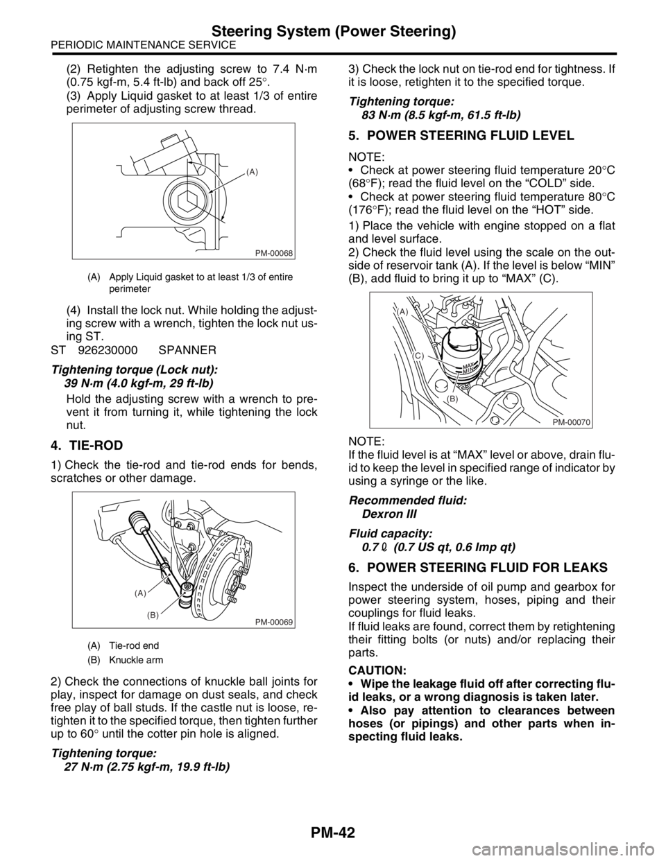
(2) Retighten the adjusting screw to 7.4 N·m
(0.75 kgf-m, 5.4 ft-lb) and back off 25°.
(3) Apply Liquid gasket to at least 1/3 of entire
perimeter of adjusting screw thread.
(4) Install the lock nut. While holding the adjust-
ing screw with a wrench, tighten the lock nut us-
ing ST.
ST 926230000 SPANNER
Tightening torque (Lock nut):
39 N·m (4.0 kgf-m, 29 ft-lb)
Hold the adjusting screw with a wrench to pre-
vent it from turning it, while tightening the lock
nut.
4. TIE-ROD
1) Check the tie-rod and tie-rod ends for bends,
scratches or other damage.
2) Check the connections of knuckle ball joints for
play, inspect for damage on dust seals, and check
free play of ball studs. If the castle nut is loose, re-
tighten it to the specified torque, then tighten further
up to 60° until the cotter pin hole is aligned.
Tightening torque:
27 N·m (2.75 kgf-m, 19.9 ft-lb)3) Check the lock nut on tie-rod end for tightness. If
it is loose, retighten it to the specified torque.
Tightening torque:
83 N·m (8.5 kgf-m, 61.5 ft-lb)
5. POWER STEERING FLUID LEVEL
NOTE:
Check at power steering fluid temperature 20°C
(68°F); read the fluid level on the “COLD” side.
Check at power steering fluid temperature 80°C
(176°F); read the fluid level on the “HOT” side.
1) Place the vehicle with engine stopped on a flat
and level surface.
2) Check the fluid level using the scale on the out-
side of reservoir tank (A). If the level is below “MIN”
(B), add fluid to bring it up to “MAX” (C).
NOTE:
If the fluid level is at “MAX” level or above, drain flu-
id to keep the level in specified range of indicator by
using a syringe or the like.
Recommended fluid:
Dexron III
Fluid capacity:
0.72 (0.7 US qt, 0.6 Imp qt)
6. POWER STEERING FLUID FOR LEAKS
Inspect the underside of oil pump and gearbox for
power steering system, hoses, piping and their
couplings for fluid leaks.
If fluid leaks are found, correct them by retightening
their fitting bolts (or nuts) and/or replacing their
parts.
CAUTION:
Wipe the leakage fluid off after correcting flu-
id leaks, or a wrong diagnosis is taken later.
Also pay attention to clearances between
hoses (or pipings) and other parts when in-
specting fluid leaks.
(A) Apply Liquid gasket to at least 1/3 of entire
perimeter
(A) Tie-rod end
(B) Knuckle arm
PM-00068
(A)
PM-00069
(A)
(B)
PM-00070
(A)
(C)
(B)