2004 SUBARU FORESTER cam sprocket
[x] Cancel search: cam sprocketPage 1457 of 2870
MECHANICAL
ME(H4DOTC)
Page
1. General Description ....................................................................................2
2. Compression .............................................................................................31
3. Idle Speed .................................................................................................32
4. Ignition Timing ...........................................................................................33
5. Intake Manifold Vacuum............................................................................34
6. Engine Oil Pressure ..................................................................................35
7. Fuel Pressure ............................................................................................36
8. Valve Clearance ........................................................................................37
9. Engine Assembly ......................................................................................41
10. Engine Mounting .......................................................................................50
11. Preparation for Overhaul ...........................................................................51
12. V-belt .........................................................................................................52
13. Crank Pulley ..............................................................................................55
14. Timing Belt Cover......................................................................................57
15. Timing Belt Assembly................................................................................58
16. Cam Sprocket ...........................................................................................67
17. Crank Sprocket .........................................................................................68
18. Camshaft ...................................................................................................69
19. Cylinder Head Assembly ...........................................................................76
20. Cylinder Block ...........................................................................................84
21. Intake and Exhaust Valve .......................................................................115
22. Piston ......................................................................................................116
23. Connecting Rod ......................................................................................117
24. Crankshaft ...............................................................................................118
25. Engine Trouble in General ......................................................................119
26. Engine Noise ...........................................................................................124
Page 1466 of 2870
ME(H4DOTC)-10
MECHANICAL
General Description
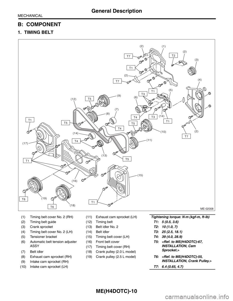
B: COMPONENT
1. TIMING BELT
(1) Timing belt cover No. 2 (RH) (11) Exhaust cam sprocket (LH)Tightening torque: N⋅m (kgf-m, ft-lb)
(2) Timing belt guide (12) Timing beltT1: 5 (0.5, 3.6)
(3) Crank sprocket (13) Belt idler No. 2T2: 10 (1.0, 7)
(4) Timing belt cover No. 2 (LH) (14) Belt idlerT3: 25 (2.5, 18.1)
(5) Tensioner bracket (15) Timing belt cover (LH)T4: 39 (4.0, 28.9)
(6) Automatic belt tension adjuster
ASSY(16) Front belt coverT5:
Sprocket.> (17) Timing belt cover (RH)
(7) Belt idler (18) Crank pulley (2.0 L model)
(8) Exhaust cam sprocket (RH) (19) Crank pulley (2.5 L model)T6:
(9) Intake cam sprocket (RH)
(10) Intake cam sprocket (LH)T7: 6.4 (0.65, 4.7)
ME-02008
T5
T1T6(7)(6)
(10)
(19)(5)
(14)(2)
(3)
T2
(4)
(1)(2)
(2)
T7
T4
T3
T3
T4
T5
T4
T5T1
T7(11)
(15)
(17)
(2)
(9)
(8)
(13) (14) (12)
T1
T1
T7
T1
T1
T5
(16)
T6(18)
Page 1481 of 2870
ME(H4DOTC)-25
MECHANICAL
General Description
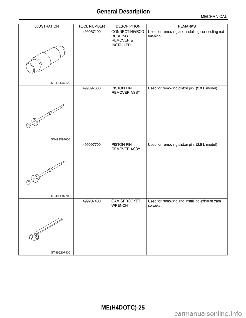
499037100 CONNECTING ROD
BUSHING
REMOVER &
INSTALLERUsed for removing and installing connecting rod
bushing.
499097600 PISTON PIN
REMOVER ASSYUsed for removing piston pin. (2.0 L model)
499097700 PISTON PIN
REMOVER ASSYUsed for removing piston pin. (2.5 L model)
499207400 CAM SPROCKET
WRENCHUsed for removing and installing exhaust cam
sprocket ILLUSTRATION TOOL NUMBER DESCRIPTION REMARKS
ST-499037100
ST-499097600
ST-499097700
ST-499207400
Page 1482 of 2870
ME(H4DOTC)-26
MECHANICAL
General Description
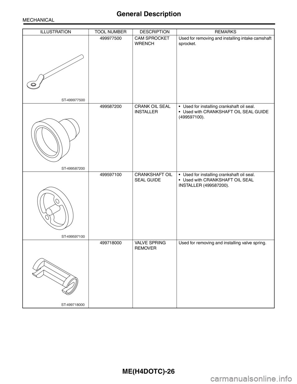
499977500 CAM SPROCKET
WRENCHUsed for removing and installing intake camshaft
sprocket.
499587200 CRANK OIL SEAL
INSTALLER Used for installing crankshaft oil seal.
Used with CRANKSHAFT OIL SEAL GUIDE
(499597100).
499597100 CRANKSHAFT OIL
SEAL GUIDE Used for installing crankshaft oil seal.
Used with CRANKSHAFT OIL SEAL
INSTALLER (499587200).
499718000 VALVE SPRING
REMOVERUsed for removing and installing valve spring. ILLUSTRATION TOOL NUMBER DESCRIPTION REMARKS
ST-499977500
ST-499587200
ST-499597100
ST-499718000
Page 1494 of 2870
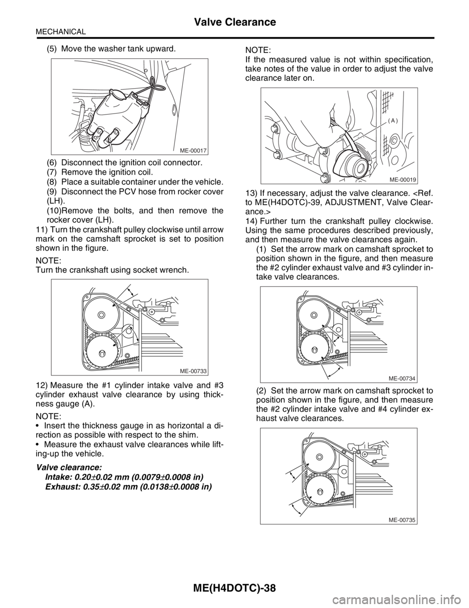
ME(H4DOTC)-38
MECHANICAL
Valve Clearance
(5) Move the washer tank upward.
(6) Disconnect the ignition coil connector.
(7) Remove the ignition coil.
(8) Place a suitable container under the vehicle.
(9) Disconnect the PCV hose from rocker cover
(LH).
(10)Remove the bolts, and then remove the
rocker cover (LH).
11) Turn the crankshaft pulley clockwise until arrow
mark on the camshaft sprocket is set to position
shown in the figure.
NOTE:
Turn the crankshaft using socket wrench.
12) Measure the #1 cylinder intake valve and #3
cylinder exhaust valve clearance by using thick-
ness gauge (A).
NOTE:
Insert the thickness gauge in as horizontal a di-
rection as possible with respect to the shim.
Measure the exhaust valve clearances while lift-
ing-up the vehicle.
Valve clearance:
Intake: 0.20
±0.02 mm (0.0079±0.0008 in)
Exhaust: 0.35
±0.02 mm (0.0138±0.0008 in)NOTE:
If the measured value is not within specification,
take notes of the value in order to adjust the valve
clearance later on.
13) If necessary, adjust the valve clearance.
ance.>
14) Further turn the crankshaft pulley clockwise.
Using the same procedures described previously,
and then measure the valve clearances again.
(1) Set the arrow mark on camshaft sprocket to
position shown in the figure, and then measure
the #2 cylinder exhaust valve and #3 cylinder in-
take valve clearances.
(2) Set the arrow mark on camshaft sprocket to
position shown in the figure, and then measure
the #2 cylinder intake valve and #4 cylinder ex-
haust valve clearances.
ME-00017
ME-00733
ME-00019
(A)
ME-00734
ME-00735
Page 1495 of 2870
ME(H4DOTC)-39
MECHANICAL
Valve Clearance
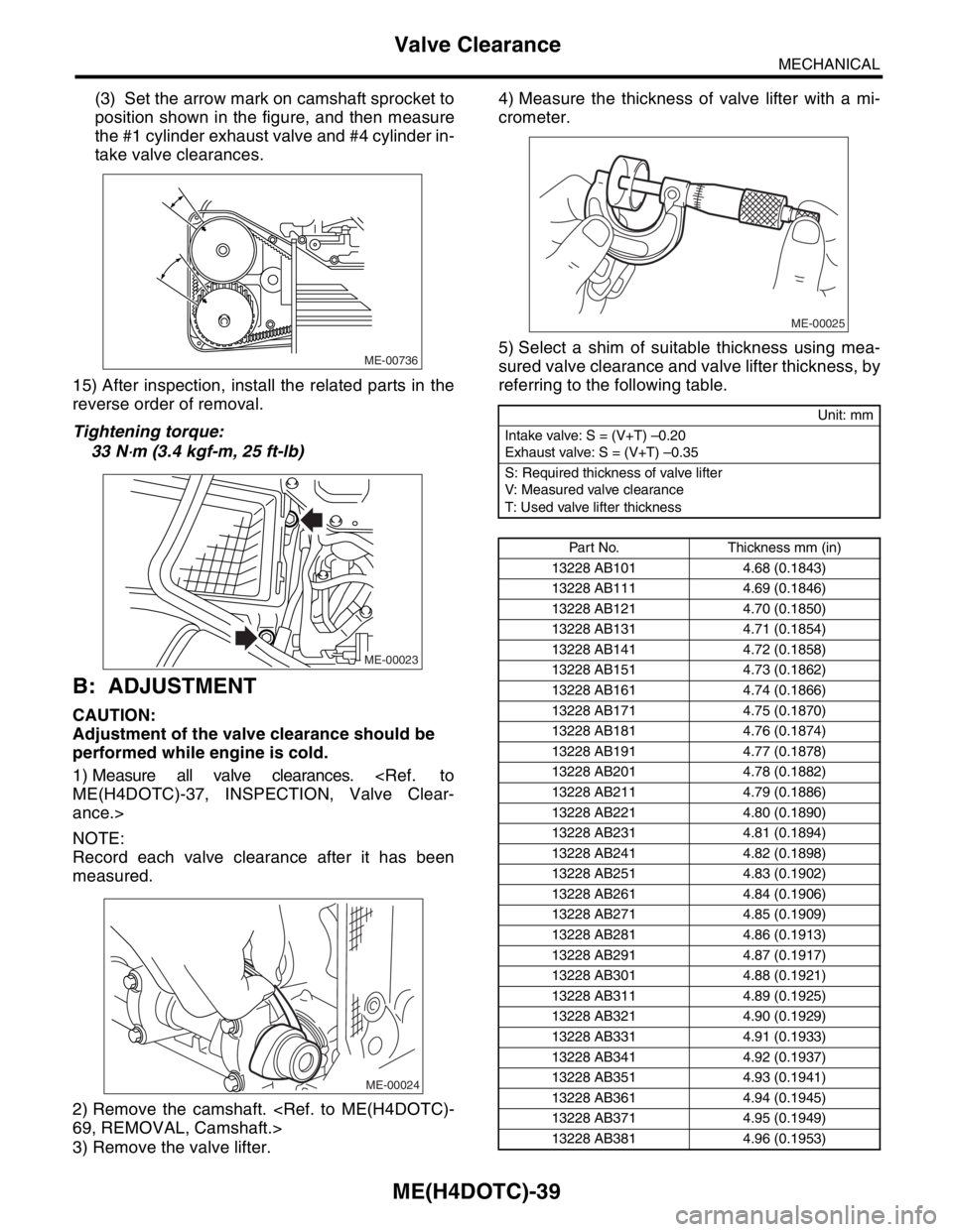
(3) Set the arrow mark on camshaft sprocket to
position shown in the figure, and then measure
the #1 cylinder exhaust valve and #4 cylinder in-
take valve clearances.
15) After inspection, install the related parts in the
reverse order of removal.
Tightening torque:
33 N
⋅m (3.4 kgf-m, 25 ft-lb)
B: ADJUSTMENT
CAUTION:
Adjustment of the valve clearance should be
performed while engine is cold.
1) Measure all valve clearances.
ance.>
NOTE:
Record each valve clearance after it has been
measured.
2) Remove the camshaft.
3) Remove the valve lifter.4) Measure the thickness of valve lifter with a mi-
crometer.
5) Select a shim of suitable thickness using mea-
sured valve clearance and valve lifter thickness, by
referring to the following table.
ME-00736
ME-00023
ME-00024
Unit: mm
Intake valve: S = (V+T) –0.20
Exhaust valve: S = (V+T) –0.35
S: Required thickness of valve lifter
V: Measured valve clearance
T: Used valve lifter thickness
Part No. Thickness mm (in)
13228 AB101 4.68 (0.1843)
13228 AB111 4.69 (0.1846)
13228 AB121 4.70 (0.1850)
13228 AB131 4.71 (0.1854)
13228 AB141 4.72 (0.1858)
13228 AB151 4.73 (0.1862)
13228 AB161 4.74 (0.1866)
13228 AB171 4.75 (0.1870)
13228 AB181 4.76 (0.1874)
13228 AB191 4.77 (0.1878)
13228 AB201 4.78 (0.1882)
13228 AB211 4.79 (0.1886)
13228 AB221 4.80 (0.1890)
13228 AB231 4.81 (0.1894)
13228 AB241 4.82 (0.1898)
13228 AB251 4.83 (0.1902)
13228 AB261 4.84 (0.1906)
13228 AB271 4.85 (0.1909)
13228 AB281 4.86 (0.1913)
13228 AB291 4.87 (0.1917)
13228 AB301 4.88 (0.1921)
13228 AB311 4.89 (0.1925)
13228 AB321 4.90 (0.1929)
13228 AB331 4.91 (0.1933)
13228 AB341 4.92 (0.1937)
13228 AB351 4.93 (0.1941)
13228 AB361 4.94 (0.1945)
13228 AB371 4.95 (0.1949)
13228 AB381 4.96 (0.1953)
ME-00025
Page 1498 of 2870
MECHANICAL
ME(H4DOTC)
Page
1. General Description ....................................................................................2
2. Compression .............................................................................................31
3. Idle Speed .................................................................................................32
4. Ignition Timing ...........................................................................................33
5. Intake Manifold Vacuum............................................................................34
6. Engine Oil Pressure ..................................................................................35
7. Fuel Pressure ............................................................................................36
8. Valve Clearance ........................................................................................37
9. Engine Assembly ......................................................................................41
10. Engine Mounting .......................................................................................50
11. Preparation for Overhaul ...........................................................................51
12. V-belt .........................................................................................................52
13. Crank Pulley ..............................................................................................55
14. Timing Belt Cover......................................................................................57
15. Timing Belt Assembly................................................................................58
16. Cam Sprocket ...........................................................................................67
17. Crank Sprocket .........................................................................................68
18. Camshaft ...................................................................................................69
19. Cylinder Head Assembly ...........................................................................76
20. Cylinder Block ...........................................................................................84
21. Intake and Exhaust Valve .......................................................................115
22. Piston ......................................................................................................116
23. Connecting Rod ......................................................................................117
24. Crankshaft ...............................................................................................118
25. Engine Trouble in General ......................................................................119
26. Engine Noise ...........................................................................................124
Page 1516 of 2870
ME(H4DOTC)-58
MECHANICAL
Timing Belt Assembly
15.Timing Belt Assembly
A: REMOVAL
1. TIMING BELT
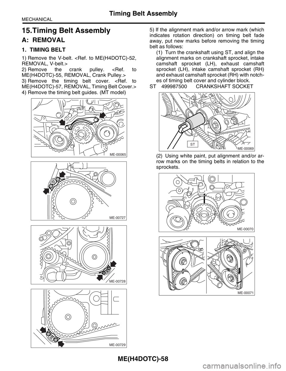
1) Remove the V-belt.
2) Remove the crank pulley.
3) Remove the timing belt cover.
4) Remove the timing belt guides. (MT model)5) If the alignment mark and/or arrow mark (which
indicates rotation direction) on timing belt fade
away, put new marks before removing the timing
belt as follows:
(1) Turn the crankshaft using ST, and align the
alignment marks on crankshaft sprocket, intake
camshaft sprocket (LH), exhaust camshaft
sprocket (LH), intake camshaft sprocket (RH)
and exhaust camshaft sprocket (RH) with notch-
es of timing belt cover and cylinder block.
ST 499987500 CRANKSHAFT SOCKET
(2) Using white paint, put alignment and/or ar-
row marks on the timing belts in relation to the
sprockets.
ME-00065
ME-00727
ME-00728
ME-00729
ME-00069ST
ME-00070
ME-00071