Page 1517 of 2870
ME(H4DOTC)-59
MECHANICAL
Timing Belt Assembly
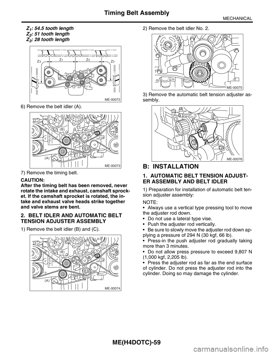
Z1: 54.5 tooth length
Z
2: 51 tooth length
Z
3: 28 tooth length
6) Remove the belt idler (A).
7) Remove the timing belt.
CAUTION:
After the timing belt has been removed, never
rotate the intake and exhaust, camshaft sprock-
et. If the camshaft sprocket is rotated, the in-
take and exhaust valve heads strike together
and valve stems are bent.
2. BELT IDLER AND AUTOMATIC BELT
TENSION ADJUSTER ASSEMBLY
1) Remove the belt idler (B) and (C).2) Remove the belt idler No. 2.
3) Remove the automatic belt tension adjuster as-
sembly.
B: INSTALLATION
1. AUTOMATIC BELT TENSION ADJUST-
ER ASSEMBLY AND BELT IDLER
1) Preparation for installation of automatic belt ten-
sion adjuster assembly:
NOTE:
Always use a vertical type pressing tool to move
the adjuster rod down.
Do not use a lateral type vise.
Push the adjuster rod vertically.
Be sure to slowly move the adjuster rod down ap-
plying a pressure of 294 N (30 kgf, 66 lb).
Press-in the push adjuster rod gradually taking
more than 3 minutes.
Do not allow press pressure to exceed 9,807 N
(1,000 kgf, 2,205 lb).
Press the adjuster rod as far as the end surface
of cylinder. Do not press the adjuster rod into the
cylinder. Doing so may damage the cylinder.
ME-00072
Z3Z1Z2Z3
ME-00073
(A)(B)
(C)
ME-00074
(A)(B)
(C)
ME-00075
ME-00076
Page 1518 of 2870
ME(H4DOTC)-60
MECHANICAL
Timing Belt Assembly
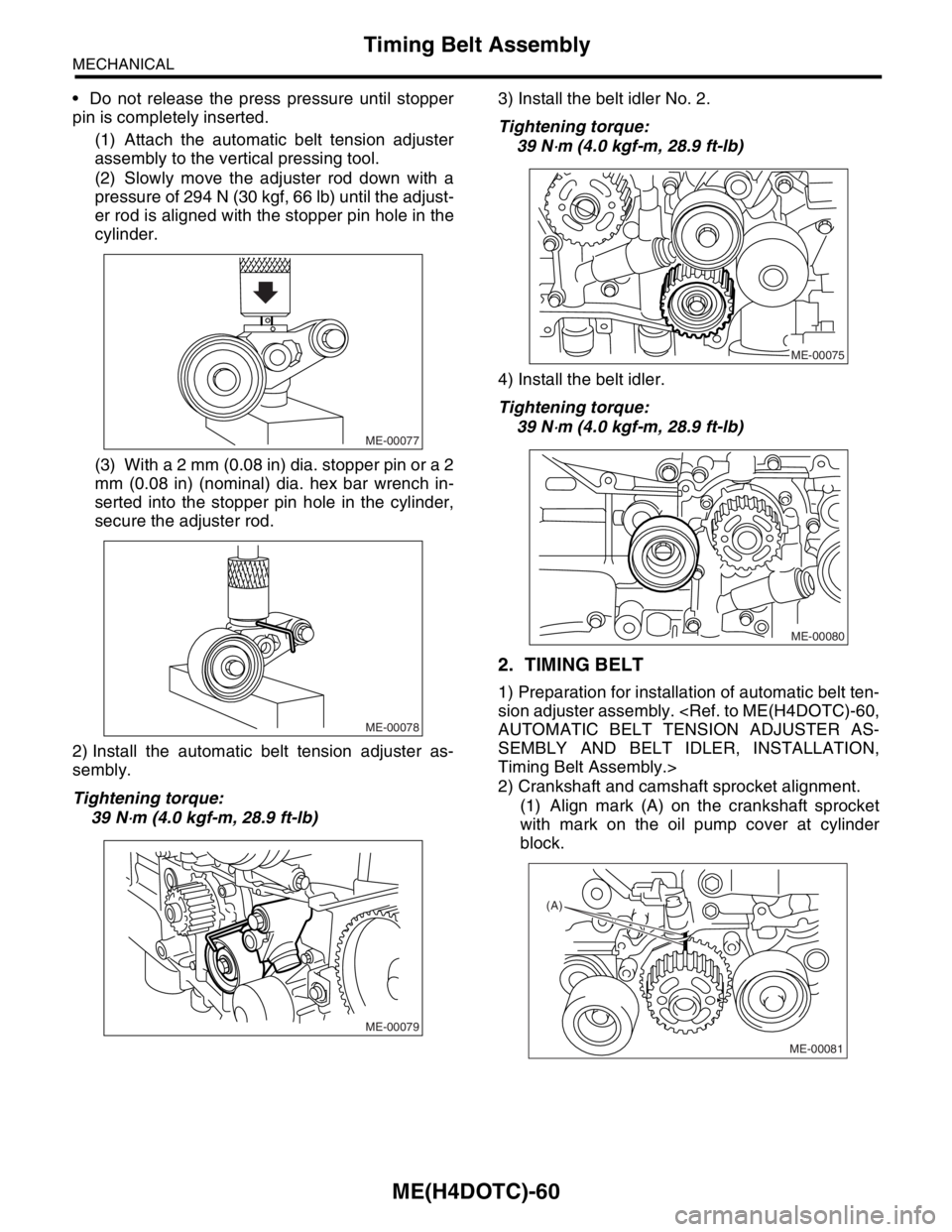
Do not release the press pressure until stopper
pin is completely inserted.
(1) Attach the automatic belt tension adjuster
assembly to the vertical pressing tool.
(2) Slowly move the adjuster rod down with a
pressure of 294 N (30 kgf, 66 lb) until the adjust-
er rod is aligned with the stopper pin hole in the
cylinder.
(3) With a 2 mm (0.08 in) dia. stopper pin or a 2
mm (0.08 in) (nominal) dia. hex bar wrench in-
serted into the stopper pin hole in the cylinder,
secure the adjuster rod.
2) Install the automatic belt tension adjuster as-
sembly.
Tightening torque:
39 N
⋅m (4.0 kgf-m, 28.9 ft-lb)3) Install the belt idler No. 2.
Tightening torque:
39 N
⋅m (4.0 kgf-m, 28.9 ft-lb)
4) Install the belt idler.
Tightening torque:
39 N
⋅m (4.0 kgf-m, 28.9 ft-lb)
2. TIMING BELT
1) Preparation for installation of automatic belt ten-
sion adjuster assembly.
AUTOMATIC BELT TENSION ADJUSTER AS-
SEMBLY AND BELT IDLER, INSTALLATION,
Timing Belt Assembly.>
2) Crankshaft and camshaft sprocket alignment.
(1) Align mark (A) on the crankshaft sprocket
with mark on the oil pump cover at cylinder
block.
ME-00077
ME-00078
ME-00079
ME-00075
ME-00080
(A)
ME-00081
Page 1519 of 2870
ME(H4DOTC)-61
MECHANICAL
Timing Belt Assembly
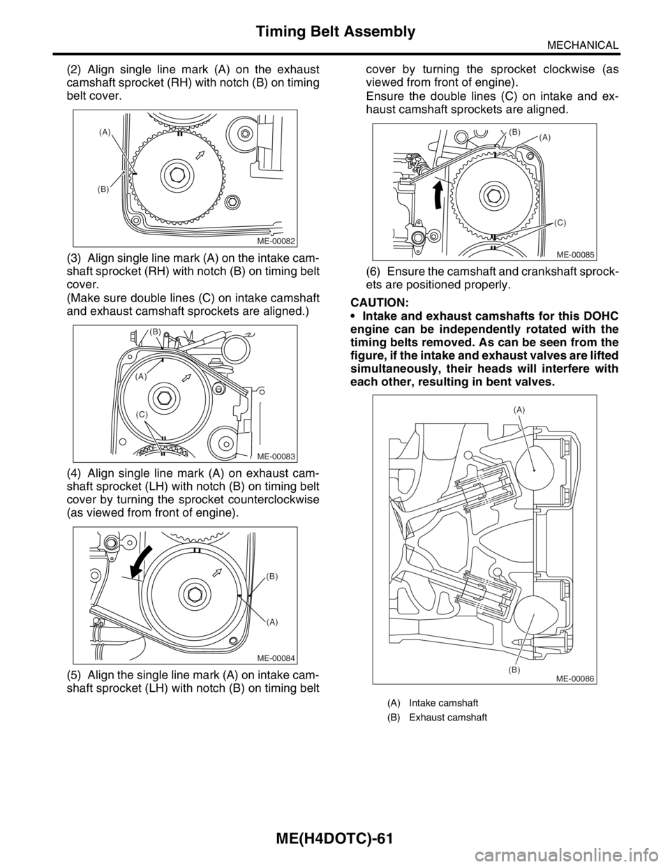
(2) Align single line mark (A) on the exhaust
camshaft sprocket (RH) with notch (B) on timing
belt cover.
(3) Align single line mark (A) on the intake cam-
shaft sprocket (RH) with notch (B) on timing belt
cover.
(Make sure double lines (C) on intake camshaft
and exhaust camshaft sprockets are aligned.)
(4) Align single line mark (A) on exhaust cam-
shaft sprocket (LH) with notch (B) on timing belt
cover by turning the sprocket counterclockwise
(as viewed from front of engine).
(5) Align the single line mark (A) on intake cam-
shaft sprocket (LH) with notch (B) on timing beltcover by turning the sprocket clockwise (as
viewed from front of engine).
Ensure the double lines (C) on intake and ex-
haust camshaft sprockets are aligned.
(6) Ensure the camshaft and crankshaft sprock-
ets are positioned properly.
CAUTION:
Intake and exhaust camshafts for this DOHC
engine can be independently rotated with the
timing belts removed. As can be seen from the
figure, if the intake and exhaust valves are lifted
simultaneously, their heads will interfere with
each other, resulting in bent valves.
ME-00082
(A)
(B)
ME-00083
(B)
(C)
(A)
ME-00084
(B)
(A)
(A) Intake camshaft
(B) Exhaust camshaft
ME-00085
(A) (B)
(C)
ME-00086
(A)
(B)
Page 1524 of 2870
ME(H4DOTC)-66
MECHANICAL
Cam Sprocket
16.Cam Sprocket
A: REMOVAL
1) Remove the V-belt.
REMOVAL, V-belt.>
2) Remove the crank pulley.
ME(H4DOTC)-55, REMOVAL, Crank Pulley.>
3) Remove the timing belt cover.
ME(H4DOTC)-57, REMOVAL, Timing Belt Cover.>
4) Remove the timing belt assembly.
ME(H4DOTC)-58, REMOVAL, Timing Belt Assem-
bly.>
5) Remove the camshaft position sensor. (2.0 L
model)
Camshaft Position Sensor.>
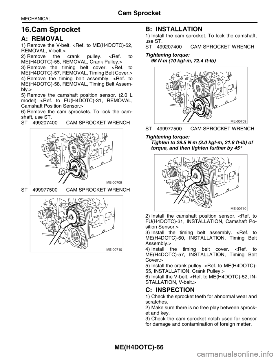
6) Remove the cam sprockets. To lock the cam-
shaft, use ST.
ST 499207400 CAM SPROCKET WRENCH
ST 499977500 CAM SPROCKET WRENCH
B: INSTALLATION
1) Install the cam sprocket. To lock the camshaft,
use ST.
ST 499207400 CAM SPROCKET WRENCH
Tightening torque:
98 N
⋅m (10 kgf-m, 72.4 ft-lb)
ST 499977500 CAM SPROCKET WRENCH
Tightening torque:
Tighten to 29.5 N
⋅m (3.0 kgf-m, 21.8 ft-lb) of
torque, and then tighten further by 45
°
2) Install the camshaft position sensor.
FU(H4DOTC)-31, INSTALLATION, Camshaft Po-
sition Sensor.>
3) Install the timing belt assembly.
ME(H4DOTC)-60, INSTALLATION, Timing Belt
Assembly.>
4) Install the timing belt cover.
ME(H4DOTC)-57, INSTALLATION, Timing Belt
Cover.>
5) Install the crank pulley.
55, INSTALLATION, Crank Pulley.>
6) Install the V-belt.
STALLATION, V-belt.>
C: INSPECTION
1) Check the sprocket teeth for abnormal wear and
scratches.
2) Make sure there is no free play between sprock-
et and key.
3) Check the cam sprocket notch used for sensor
for damage and contamination of foreign matter.
ME-00709
ME-00710
ME-00709
ME-00710
Page 1525 of 2870
ME(H4DOTC)-67
MECHANICAL
Crank Sprocket
17.Crank Sprocket
A: REMOVAL
1) Remove the V-belt.
REMOVAL, V-belt.>
2) Remove the crank pulley.
55, REMOVAL, Crank Pulley.>
3) Remove the timing belt cover.
ME(H4DOTC)-57, REMOVAL, Timing Belt Cover.>
4) Remove the timing belt assembly.
ME(H4DOTC)-58, REMOVAL, Timing Belt Assem-
bly.>
5) Remove the cam sprocket.
ME(H4DOTC)-67, REMOVAL, Cam Sprocket.>
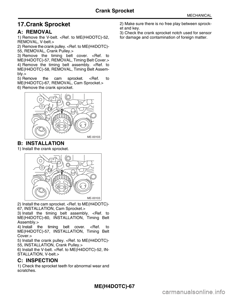
6) Remove the crank sprocket.
B: INSTALLATION
1) Install the crank sprocket.
2) Install the cam sprocket.
67, INSTALLATION, Cam Sprocket.>
3) Install the timing belt assembly.
ME(H4DOTC)-60, INSTALLATION, Timing Belt
Assembly.>
4) Install the timing belt cover.
ME(H4DOTC)-57, INSTALLATION, Timing Belt
Cover.>
5) Install the crank pulley.
55, INSTALLATION, Crank Pulley.>
6) Install the V-belt.
STALLATION, V-belt.>
C: INSPECTION
1) Check the sprocket teeth for abnormal wear and
scratches.2) Make sure there is no free play between sprock-
et and key.
3) Check the crank sprocket notch used for sensor
for damage and contamination of foreign matter.
ME-00103
ME-00103
Page 1526 of 2870
ME(H4DOTC)-68
MECHANICAL
Camshaft
18.Camshaft
A: REMOVAL
1) Remove the V-belt.
INSTALLATION, V-belt.>
2) Remove the crank pulley.
55, REMOVAL, Crank Pulley.>
3) Remove the timing belt cover.
ME(H4DOTC)-57, REMOVAL, Timing Belt Cover.>
4) Remove the timing belt assembly.
ME(H4DOTC)-58, REMOVAL, Timing Belt Assem-
bly.>
5) Remove the cam sprocket.
ME(H4DOTC)-67, REMOVAL, Cam Sprocket.>
6) Remove the crank sprocket.
ME(H4DOTC)-68, REMOVAL, Crank Sprocket.>
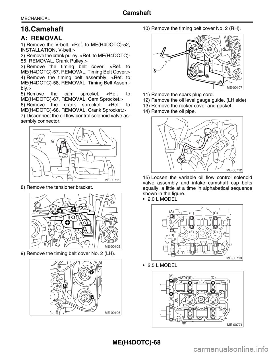
7) Disconnect the oil flow control solenoid valve as-
sembly connector.
8) Remove the tensioner bracket.
9) Remove the timing belt cover No. 2 (LH).10) Remove the timing belt cover No. 2 (RH).
11) Remove the spark plug cord.
12) Remove the oil level gauge guide. (LH side)
13) Remove the rocker cover and gasket.
14) Remove the oil pipe.
15) Loosen the variable oil flow control solenoid
valve assembly and intake camshaft cap bolts
equally, a little at a time in alphabetical sequence
shown in the figure.
2.0 L MODEL
2.5 L MODEL
ME-00711
ME-00105
ME-00106
ME-00107
ME-00712
ME-00713
(B)
(A)
(E)
(F) (D)(C)
ME-00771
(A)(E)
(F)(B)(D)
(C)
Page 1530 of 2870
ME(H4DOTC)-72
MECHANICAL
Camshaft
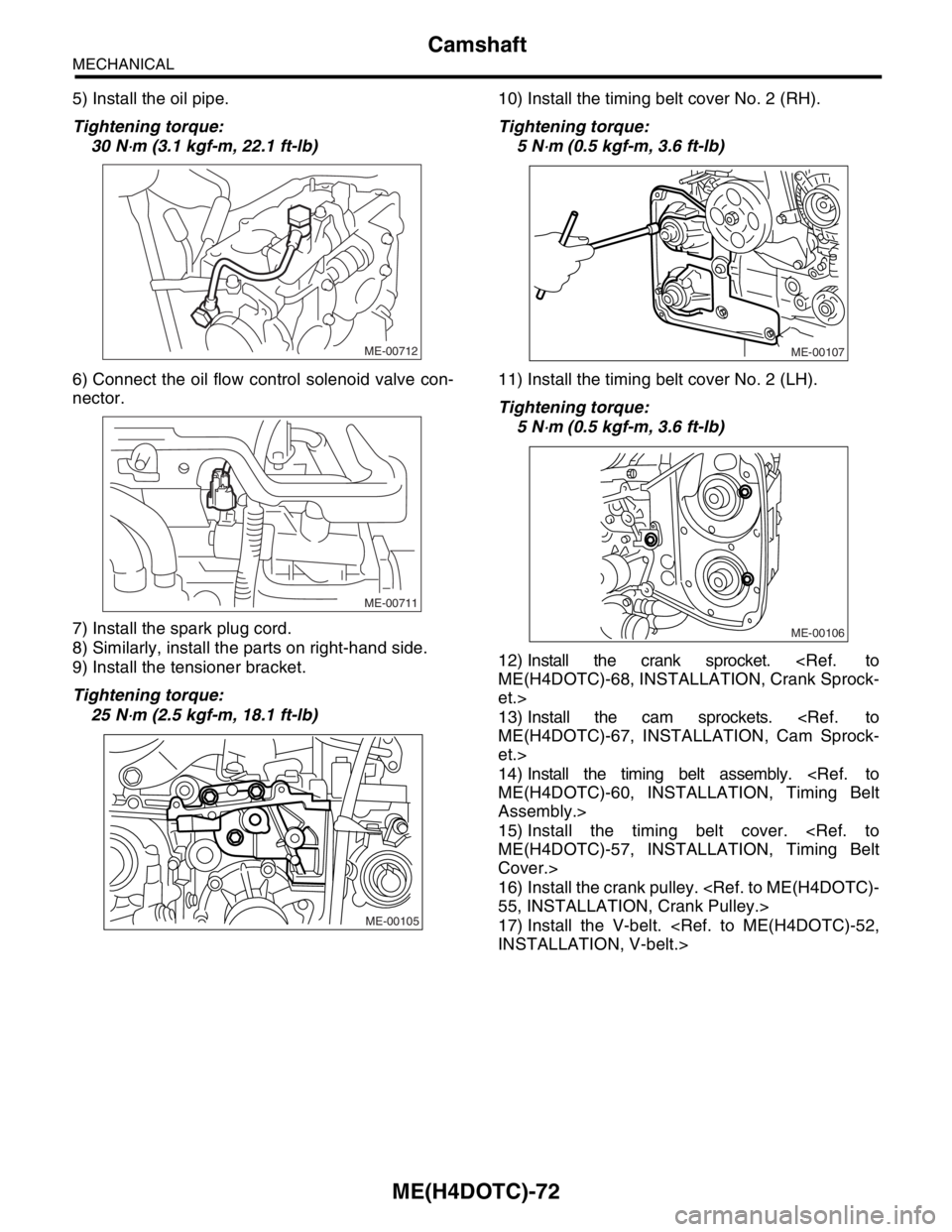
5) Install the oil pipe.
Tightening torque:
30 N
⋅m (3.1 kgf-m, 22.1 ft-lb)
6) Connect the oil flow control solenoid valve con-
nector.
7) Install the spark plug cord.
8) Similarly, install the parts on right-hand side.
9) Install the tensioner bracket.
Tightening torque:
25 N
⋅m (2.5 kgf-m, 18.1 ft-lb)10) Install the timing belt cover No. 2 (RH).
Tightening torque:
5 N
⋅m (0.5 kgf-m, 3.6 ft-lb)
11) Install the timing belt cover No. 2 (LH).
Tightening torque:
5 N
⋅m (0.5 kgf-m, 3.6 ft-lb)
12) Install the crank sprocket.
ME(H4DOTC)-68, INSTALLATION, Crank Sprock-
et.>
13) Install the cam sprockets.
ME(H4DOTC)-67, INSTALLATION, Cam Sprock-
et.>
14) Install the timing belt assembly.
ME(H4DOTC)-60, INSTALLATION, Timing Belt
Assembly.>
15) Install the timing belt cover.
ME(H4DOTC)-57, INSTALLATION, Timing Belt
Cover.>
16) Install the crank pulley.
55, INSTALLATION, Crank Pulley.>
17) Install the V-belt.
INSTALLATION, V-belt.>
ME-00712
ME-00711
ME-00105
ME-00107
ME-00106
Page 1533 of 2870
ME(H4DOTC)-75
MECHANICAL
Cylinder Head Assembly
19.Cylinder Head Assembly
A: REMOVAL
1) Remove the V-belt.
REMOVAL, V-belt.>
2) Remove the crank pulley.
ME(H4DOTC)-55, REMOVAL, Crank Pulley.>
3) Remove the timing belt cover.
ME(H4DOTC)-57, REMOVAL, Timing Belt Cover.>
4) Remove the timing belt assembly.
ME(H4DOTC)-58, REMOVAL, Timing Belt Assem-
bly.>
5) Remove the cam sprocket.
ME(H4DOTC)-67, REMOVAL, Cam Sprocket.>
6) Remove the intake manifold.
FU(H4DOTC)-14, REMOVAL, Intake Manifold.>
7) Remove the bolt which installs the A/C compres-
sor bracket on cylinder head.
8) Remove the camshaft.
69, REMOVAL, Camshaft.>
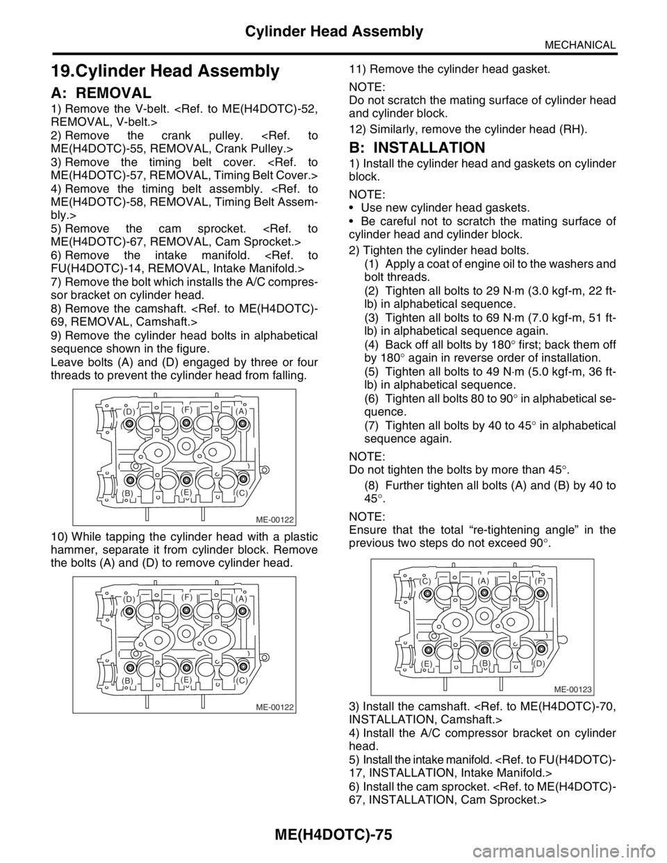
9) Remove the cylinder head bolts in alphabetical
sequence shown in the figure.
Leave bolts (A) and (D) engaged by three or four
threads to prevent the cylinder head from falling.
10) While tapping the cylinder head with a plastic
hammer, separate it from cylinder block. Remove
the bolts (A) and (D) to remove cylinder head.11) Remove the cylinder head gasket.
NOTE:
Do not scratch the mating surface of cylinder head
and cylinder block.
12) Similarly, remove the cylinder head (RH).
B: INSTALLATION
1) Install the cylinder head and gaskets on cylinder
block.
NOTE:
Use new cylinder head gaskets.
Be careful not to scratch the mating surface of
cylinder head and cylinder block.
2) Tighten the cylinder head bolts.
(1) Apply a coat of engine oil to the washers and
bolt threads.
(2) Tighten all bolts to 29 N⋅m (3.0 kgf-m, 22 ft-
lb) in alphabetical sequence.
(3) Tighten all bolts to 69 N⋅m (7.0 kgf-m, 51 ft-
lb) in alphabetical sequence again.
(4) Back off all bolts by 180° first; back them off
by 180° again in reverse order of installation.
(5) Tighten all bolts to 49 N⋅m (5.0 kgf-m, 36 ft-
lb) in alphabetical sequence.
(6) Tighten all bolts 80 to 90° in alphabetical se-
quence.
(7) Tighten all bolts by 40 to 45° in alphabetical
sequence again.
NOTE:
Do not tighten the bolts by more than 45°.
(8) Further tighten all bolts (A) and (B) by 40 to
45°.
NOTE:
Ensure that the total “re-tightening angle” in the
previous two steps do not exceed 90°.
3) Install the camshaft.
INSTALLATION, Camshaft.>
4) Install the A/C compressor bracket on cylinder
head.
5) Install the intake manifold.
17, INSTALLATION, Intake Manifold.>
6) Install the cam sprocket.
67, INSTALLATION, Cam Sprocket.>
ME-00122
(B)(C)
(D)
(E)
(F)(A)
ME-00122
(B)(C)
(D)
(E)
(F)(A)
ME-00123
(B)
(C)
(D)(E)
(F)(A)