2004 SUBARU FORESTER cam sprocket
[x] Cancel search: cam sprocketPage 926 of 2870
ME(H4SO)-55
MECHANICAL
Crank Sprocket
17.Crank Sprocket
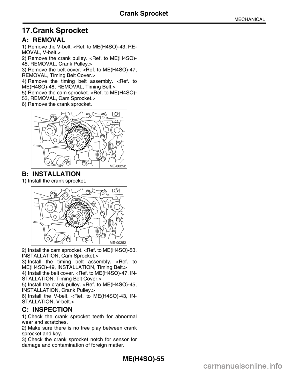
A: REMOVAL
1) Remove the V-belt.
2) Remove the crank pulley.
3) Remove the belt cover.
4) Remove the timing belt assembly.
5) Remove the cam sprocket.
6) Remove the crank sprocket.
B: INSTALLATION
1) Install the crank sprocket.
2) Install the cam sprocket.
3) Install the timing belt assembly.
4) Install the belt cover.
5) Install the crank pulley.
6) Install the V-belt.
C: INSPECTION
1) Check the crank sprocket teeth for abnormal
wear and scratches.
2) Make sure there is no free play between crank
sprocket and key.
3) Check the crank sprocket notch for sensor for
damage and contamination of foreign matter.
ME-00252
ME-00252
Page 927 of 2870
ME(H4SO)-56
MECHANICAL
Valve Rocker Assembly
18.Valve Rocker Assembly
A: REMOVAL
1) Remove the V-belt.
2) Remove the crank pulley.
3) Remove the belt cover.
4) Remove the timing belt assembly.
5) Remove the cam sprocket.
6) Disconnect the PCV hose and remove rocker
cover.
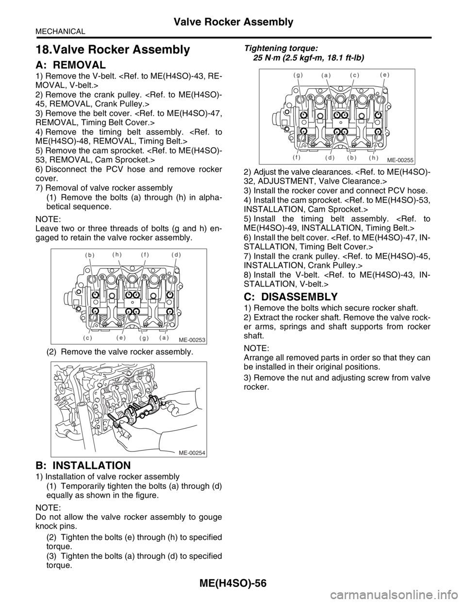
7) Removal of valve rocker assembly
(1) Remove the bolts (a) through (h) in alpha-
betical sequence.
NOTE:
Leave two or three threads of bolts (g and h) en-
gaged to retain the valve rocker assembly.
(2) Remove the valve rocker assembly.
B: INSTALLATION
1) Installation of valve rocker assembly
(1) Temporarily tighten the bolts (a) through (d)
equally as shown in the figure.
NOTE:
Do not allow the valve rocker assembly to gouge
knock pins.
(2) Tighten the bolts (e) through (h) to specified
torque.
(3) Tighten the bolts (a) through (d) to specified
torque.Tightening torque:
25 N
⋅m (2.5 kgf-m, 18.1 ft-lb)
2) Adjust the valve clearances.
3) Install the rocker cover and connect PCV hose.
4) Install the cam sprocket.
5) Install the timing belt assembly.
6) Install the belt cover.
7) Install the crank pulley.
8) Install the V-belt.
C: DISASSEMBLY
1) Remove the bolts which secure rocker shaft.
2) Extract the rocker shaft. Remove the valve rock-
er arms, springs and shaft supports from rocker
shaft.
NOTE:
Arrange all removed parts in order so that they can
be installed in their original positions.
3) Remove the nut and adjusting screw from valve
rocker.
ME-00253(a) (b)
(c)(d)
(e)(f)
(g) (h)
ME-00254
ME-00255
(a)
(b)(c)
(d)(e)
(f)(g)
(h)
Page 929 of 2870
ME(H4SO)-58
MECHANICAL
Camshaft
19.Camshaft
A: REMOVAL
1) Remove the V-belt.
2) Remove the crank pulley.
3) Remove the belt cover.
4) Remove the timing belt assembly.
5) Remove the cam sprocket.
6) Remove the crank sprocket.
7) Remove the belt cover No. 2 (LH).
8) Remove the belt cover No. 2 (RH).
NOTE:
Do not damage or lose the seal rubber when re-
moving belt covers.
9) Remove the tensioner bracket.
10) Remove the camshaft position sensor support.
(LH side only)
11) Remove the oil level gauge guide. (LH side only)
12) Remove the valve rocker assembly.
bly.>
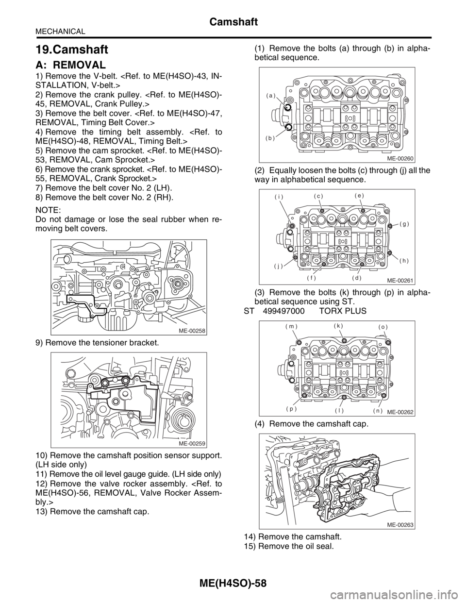
13) Remove the camshaft cap.(1) Remove the bolts (a) through (b) in alpha-
betical sequence.
(2) Equally loosen the bolts (c) through (j) all the
way in alphabetical sequence.
(3) Remove the bolts (k) through (p) in alpha-
betical sequence using ST.
ST 499497000 TORX PLUS
(4) Remove the camshaft cap.
14) Remove the camshaft.
15) Remove the oil seal.
ME-00258
ME-00259
ME-00260
(b)(a)
ME-00261
(c)(e)
(g)
(h)
(d) (f) (j)(i)
ME-00262
(k)
(o)
(n) (l) (p) (m)
ME-00263
Page 931 of 2870
ME(H4SO)-60
MECHANICAL
Camshaft
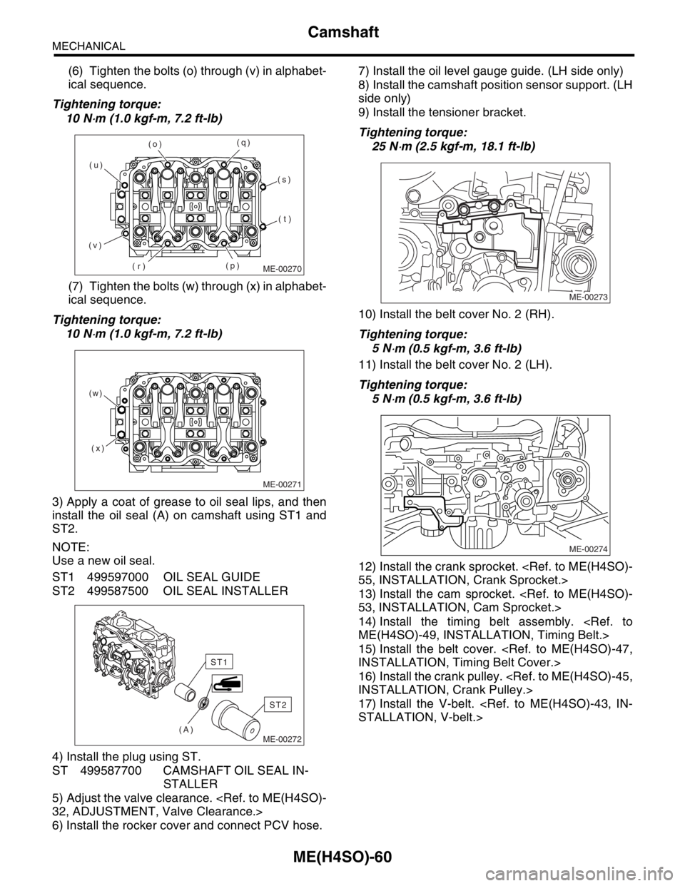
(6) Tighten the bolts (o) through (v) in alphabet-
ical sequence.
Tightening torque:
10 N
⋅m (1.0 kgf-m, 7.2 ft-lb)
(7) Tighten the bolts (w) through (x) in alphabet-
ical sequence.
Tightening torque:
10 N
⋅m (1.0 kgf-m, 7.2 ft-lb)
3) Apply a coat of grease to oil seal lips, and then
install the oil seal (A) on camshaft using ST1 and
ST2.
NOTE:
Use a new oil seal.
ST1 499597000 OIL SEAL GUIDE
ST2 499587500 OIL SEAL INSTALLER
4) Install the plug using ST.
ST 499587700 CAMSHAFT OIL SEAL IN-
STALLER
5) Adjust the valve clearance.
6) Install the rocker cover and connect PCV hose.7) Install the oil level gauge guide. (LH side only)
8) Install the camshaft position sensor support. (LH
side only)
9) Install the tensioner bracket.
Tightening torque:
25 N
⋅m (2.5 kgf-m, 18.1 ft-lb)
10) Install the belt cover No. 2 (RH).
Tightening torque:
5 N
⋅m (0.5 kgf-m, 3.6 ft-lb)
11) Install the belt cover No. 2 (LH).
Tightening torque:
5 N
⋅m (0.5 kgf-m, 3.6 ft-lb)
12) Install the crank sprocket.
13) Install the cam sprocket.
14) Install the timing belt assembly.
15) Install the belt cover.
16) Install the crank pulley.
17) Install the V-belt.
ME-00270
(o)
(r)(q)
(v)(u)
(p)(s)
(t)
ME-00271
(x) (w)
ME-00272(A)
ST2
ST1
ME-00273
ME-00274
Page 933 of 2870
ME(H4SO)-62
MECHANICAL
Cylinder Head
20.Cylinder Head
A: REMOVAL
1) Remove the V-belt.
2) Remove the crank pulley.
3) Remove the timing belt cover.
4) Remove the timing belt.
5) Remove the cam sprocket.
6) Remove the intake manifold.
7) Remove the bolt which installs A/C compressor
bracket on cylinder head.
8) Remove the valve rocker assembly.
bly.>
9) Remove the camshaft.
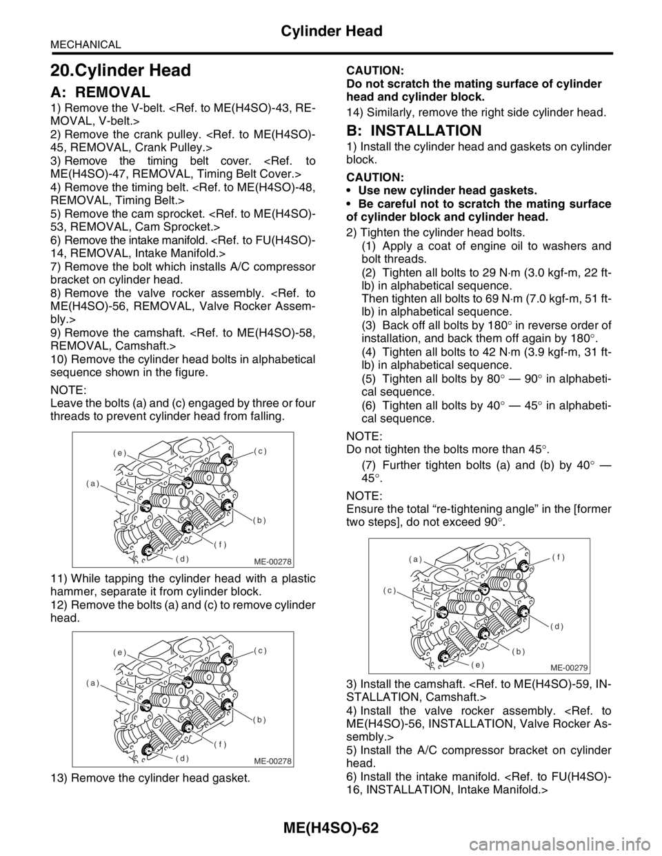
10) Remove the cylinder head bolts in alphabetical
sequence shown in the figure.
NOTE:
Leave the bolts (a) and (c) engaged by three or four
threads to prevent cylinder head from falling.
11) While tapping the cylinder head with a plastic
hammer, separate it from cylinder block.
12) Remove the bolts (a) and (c) to remove cylinder
head.
13) Remove the cylinder head gasket.CAUTION:
Do not scratch the mating surface of cylinder
head and cylinder block.
14) Similarly, remove the right side cylinder head.
B: INSTALLATION
1) Install the cylinder head and gaskets on cylinder
block.
CAUTION:
Use new cylinder head gaskets.
Be careful not to scratch the mating surface
of cylinder block and cylinder head.
2) Tighten the cylinder head bolts.
(1) Apply a coat of engine oil to washers and
bolt threads.
(2) Tighten all bolts to 29 N⋅m (3.0 kgf-m, 22 ft-
lb) in alphabetical sequence.
Then tighten all bolts to 69 N⋅m (7.0 kgf-m, 51 ft-
lb) in alphabetical sequence.
(3) Back off all bolts by 180° in reverse order of
installation, and back them off again by 180°.
(4) Tighten all bolts to 42 N⋅m (3.9 kgf-m, 31 ft-
lb) in alphabetical sequence.
(5) Tighten all bolts by 80° — 90° in alphabeti-
cal sequence.
(6) Tighten all bolts by 40° — 45° in alphabeti-
cal sequence.
NOTE:
Do not tighten the bolts more than 45°.
(7) Further tighten bolts (a) and (b) by 40° —
45°.
NOTE:
Ensure the total “re-tightening angle” in the [former
two steps], do not exceed 90°.
3) Install the camshaft.
4) Install the valve rocker assembly.
sembly.>
5) Install the A/C compressor bracket on cylinder
head.
6) Install the intake manifold.
ME-00278
(c)
(b)
(f)
(d) (a)(e)
ME-00278
(c)
(b)
(f)
(d) (a)(e)
ME-00279
(c)
(b)(f)
(d) (a)
(e)
Page 934 of 2870
ME(H4SO)-63
MECHANICAL
Cylinder Head
7) Install the cam sprocket.
8) Install the timing belt assembly.
9) Install the timing belt cover.
10) Install the crank pulley.
11) Install the V-belt.
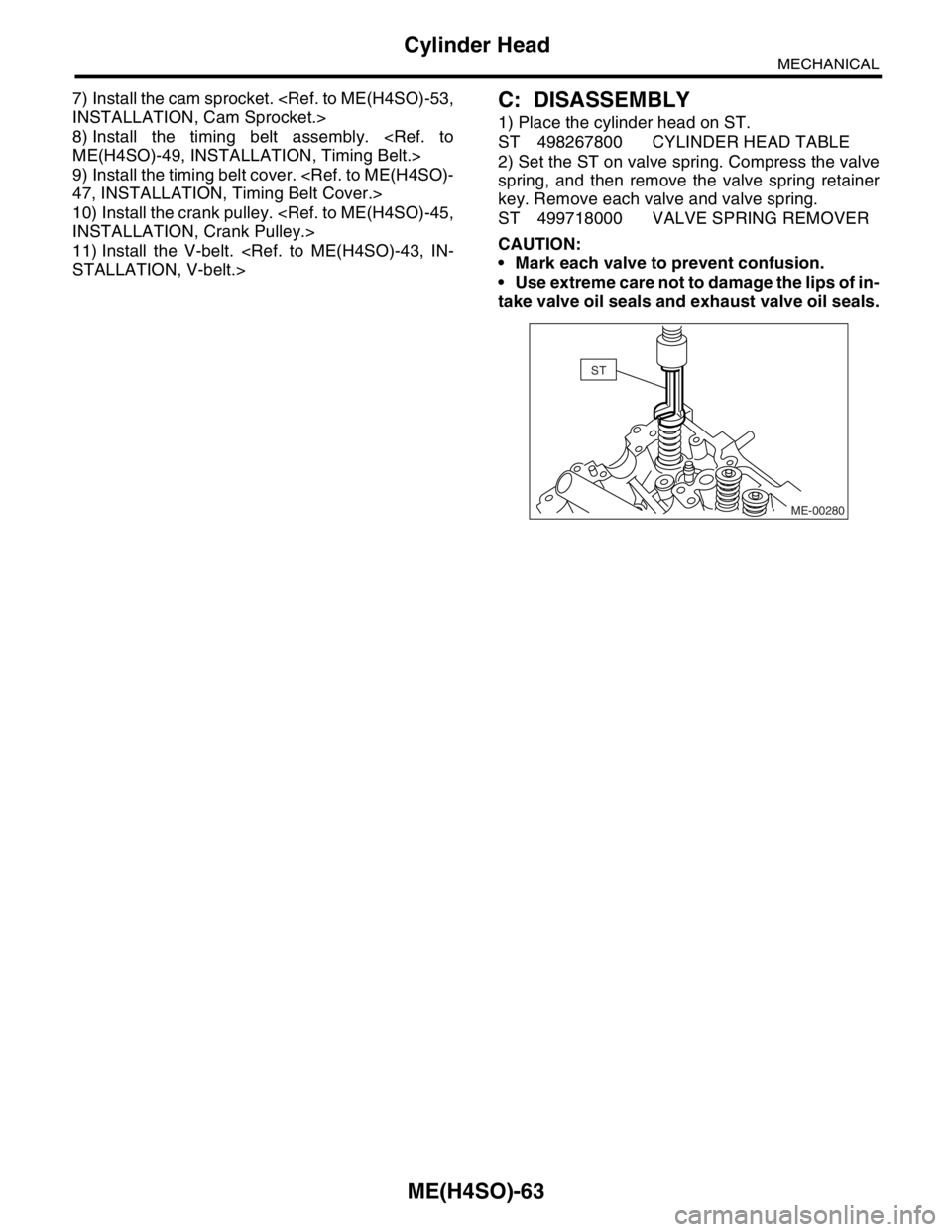
1) Place the cylinder head on ST.
ST 498267800 CYLINDER HEAD TABLE
2) Set the ST on valve spring. Compress the valve
spring, and then remove the valve spring retainer
key. Remove each valve and valve spring.
ST 499718000 VALVE SPRING REMOVER
CAUTION:
Mark each valve to prevent confusion.
Use extreme care not to damage the lips of in-
take valve oil seals and exhaust valve oil seals.
ME-00280
ST
Page 940 of 2870
ME(H4SO)-69
MECHANICAL
Cylinder Block
21.Cylinder Block
A: REMOVAL
NOTE:
Before conducting this procedure, drain the engine
oil completely.
1) Remove the intake manifold.
2) Remove the V-belt.
3) Remove the crank pulley.
4) Remove the timing belt cover.
5) Remove the timing belt.
6) Remove the cam sprocket.
7) Remove the crank sprocket.
8) Remove the generator and A/C compressor with
their brackets.
9) Remove the rocker cover.
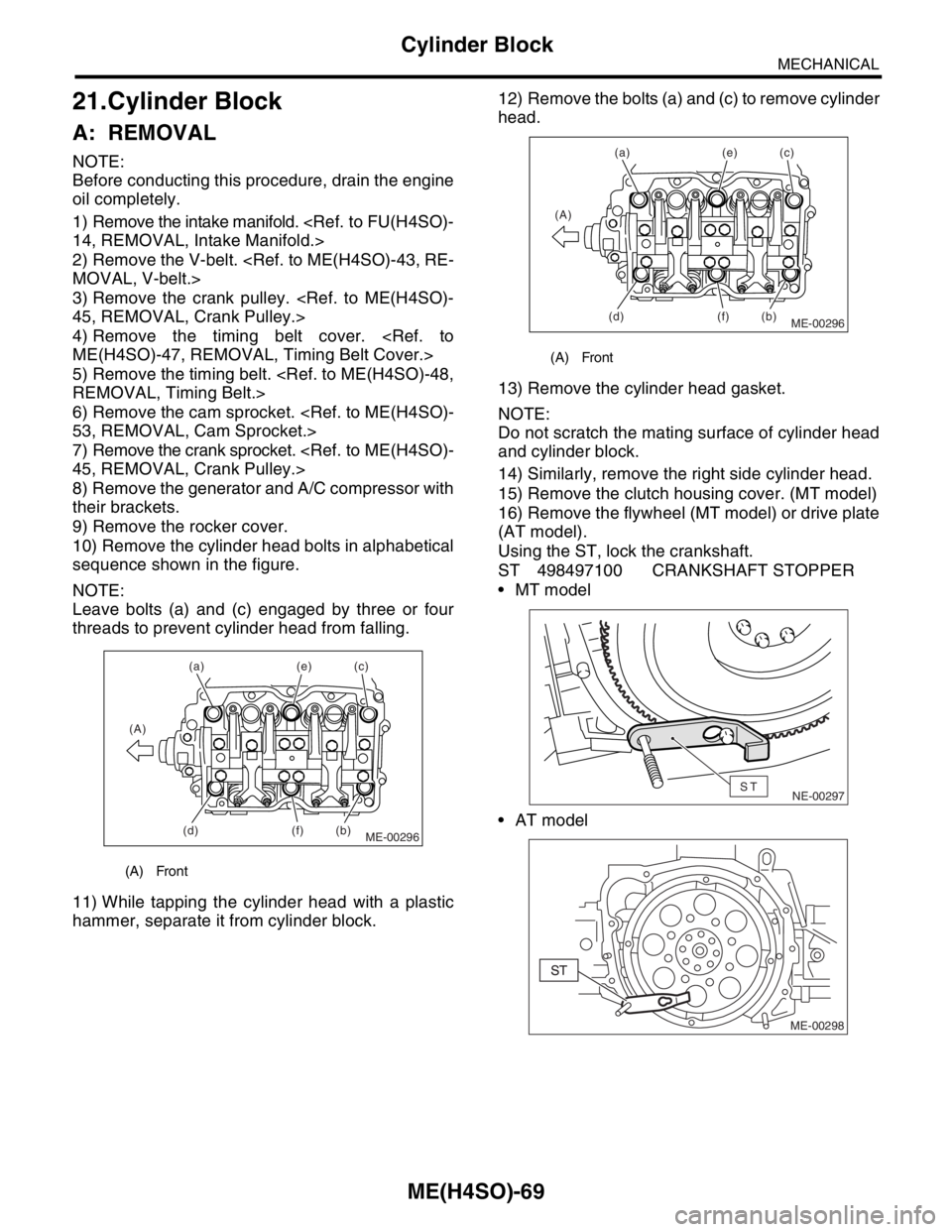
10) Remove the cylinder head bolts in alphabetical
sequence shown in the figure.
NOTE:
Leave bolts (a) and (c) engaged by three or four
threads to prevent cylinder head from falling.
11) While tapping the cylinder head with a plastic
hammer, separate it from cylinder block.12) Remove the bolts (a) and (c) to remove cylinder
head.
13) Remove the cylinder head gasket.
NOTE:
Do not scratch the mating surface of cylinder head
and cylinder block.
14) Similarly, remove the right side cylinder head.
15) Remove the clutch housing cover. (MT model)
16) Remove the flywheel (MT model) or drive plate
(AT model).
Using the ST, lock the crankshaft.
ST 498497100 CRANKSHAFT STOPPER
MT model
AT model
(A) Front
ME-00296
(a)
(b)(c) (e)
(f) (A)
(d)
(A) Front
ME-00296
(a)
(b)(c) (e)
(f) (A)
(d)
NE-00297ST
ME-00298
Page 952 of 2870
ME(H4SO)-81
MECHANICAL
Cylinder Block
Model with ATF warmer
28) Install the water by-pass pipe for heater.
29) Get a engine oil filter and apply a thin coat of
engine oil to the seal rubber.
30) Install the oil filter by turning it by hand, being
careful not to damage the seal rubber.
Tighten the oil filter 80 mm (3.15 in) or 65 mm
(2.56 in) in diameter by approx. 2/3 — 3/4 rotation
more after the seal rubber of oil filter comes in con-
tact with cylinder block or oil cooler.
Tighten the oil filter 68 mm (2.68 in) in diameter
by approx. 1 rotation more after the seal rubber of
oil filter comes in contact with cylinder block or oil
cooler.
CAUTION:
Do not tighten excessively, or oil may leak.
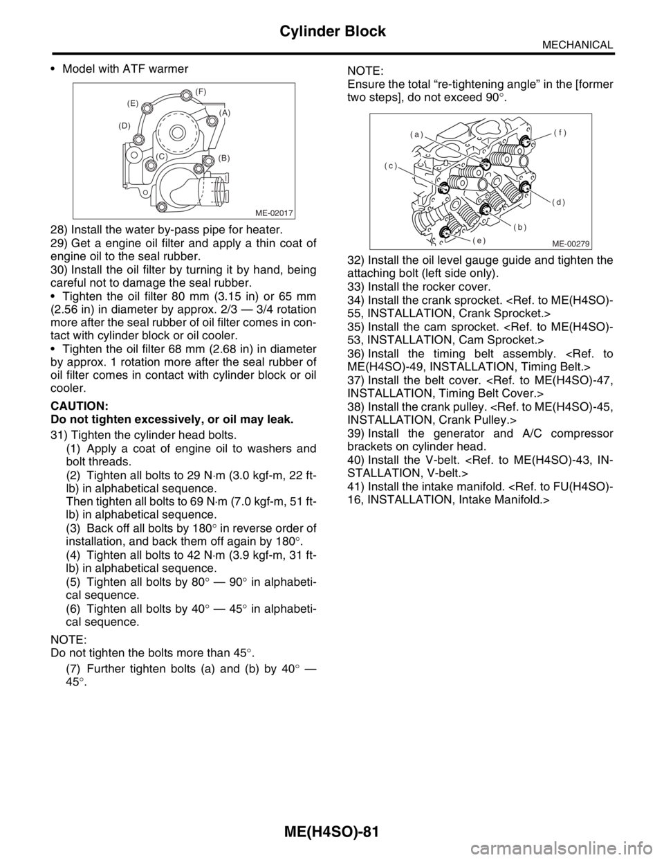
31) Tighten the cylinder head bolts.
(1) Apply a coat of engine oil to washers and
bolt threads.
(2) Tighten all bolts to 29 N⋅m (3.0 kgf-m, 22 ft-
lb) in alphabetical sequence.
Then tighten all bolts to 69 N⋅m (7.0 kgf-m, 51 ft-
lb) in alphabetical sequence.
(3) Back off all bolts by 180° in reverse order of
installation, and back them off again by 180°.
(4) Tighten all bolts to 42 N⋅m (3.9 kgf-m, 31 ft-
lb) in alphabetical sequence.
(5) Tighten all bolts by 80° — 90° in alphabeti-
cal sequence.
(6) Tighten all bolts by 40° — 45° in alphabeti-
cal sequence.
NOTE:
Do not tighten the bolts more than 45°.
(7) Further tighten bolts (a) and (b) by 40° —
45°.NOTE:
Ensure the total “re-tightening angle” in the [former
two steps], do not exceed 90°.
32) Install the oil level gauge guide and tighten the
attaching bolt (left side only).
33) Install the rocker cover.
34) Install the crank sprocket.
35) Install the cam sprocket.
36) Install the timing belt assembly.
37) Install the belt cover.
38) Install the crank pulley.
39) Install the generator and A/C compressor
brackets on cylinder head.
40) Install the V-belt.
41) Install the intake manifold.
ME-02017
(B) (C) (D)(E)(F)
(A)
ME-00279
(c)
(b)(f)
(d) (a)
(e)