Page 994 of 2870
CO(H4SO)-11
COOLING
General Description
D: PREPARATION TOOL
1. NON-TURBO MODEL
ILLUSTRATION TOOL NUMBER DESCRIPTION REMARKS
499977400
(2.0 L model)CRANK PULLEY
WRENCHUsed for stopping crank pulley when loosening
and tightening crank pulley bolts.
499977100
(2.5 L model)CRANK PULLEY
WRENCHUsed for stopping crank pulley when loosening
and tightening crank pulley bolts.
18231AA010 CAM SPROCKET
WRENCH (For left
side) Used for removing and installing cam sprocket
(LH).
Also the CAM SPROCKET WRENCH
(499207100) can be used.
499207400 CAM SPROCKET
WRENCH (For right
side)Used for removing and installing cam sprocket
(RH).
ST-499977400
ST-499977100
ST18231AA010
ST-499207400
Page 995 of 2870
CO(H4SO)-12
COOLING
General Description
2. TURBO MODEL
ILLUSTRATION TOOL NUMBER DESCRIPTION REMARKS
499977400
(2.0 L model)CRANK PULLEY
WRENCHUsed for stopping crank pulley when loosening
and tightening crank pulley bolts.
499977100
(2.5 L model)CRANK PULLEY
WRENCHUsed for stopping crank pulley when loosening
and tightening crank pulley bolts.
499977500 CAM SPROCKET
WRENCHUsed for removing and installing cam sprocket.
(Intake)
499207400 CAM SPROCKET
WRENCHUsed for removing and installing cam sprocket.
(Exhaust)
ST-499977400
ST-499977100
ST-499977500
ST-499207400
Page 1004 of 2870
CO(H4SO)-21
COOLING
Water Pump
4. Water Pump
A: REMOVAL
1. NON-TURBO MODEL
1) Remove the radiator.
REMOVAL, Radiator.>
2) Remove the V-belts.
3) Remove the timing belt.
AL, Timing Belt.>
4) Remove the automatic belt tension adjuster.
5) Remove the belt idler No. 2.
6) Remove the camshaft sprocket (LH) by using
ST.
ST 18231AA010 CAM SPROCKET WRENCH
NOTE:
Also the CAM SPROCKET WRENCH (499207100)
can be used.7) Remove the belt cover No. 2 (LH).
8) Remove the tensioner bracket.
9) Disconnect the hose from water pump.
10) Remove the water pump.
CO-00016
CO-00017
CO-00018
ST
CO-00019
CO-00020
CO-00021
Page 1005 of 2870
CO(H4SO)-22
COOLING
Water Pump
2. TURBO MODEL
1) Remove the radiator.
REMOVAL, Radiator.>
2) Remove the V-belts.
REMOVAL, V-belt.>
3) Remove the timing belt.
58, REMOVAL, Timing Belt Assembly.>
4) Remove the automatic belt tension adjuster (A).
5) Remove the belt idler (B).
6) Remove the belt idler No. 2 (C).
7) Remove the camshaft position sensor. (2.0 L mod-
el)
shaft Position Sensor.>
8) Remove the cam sprockets (LH) by using ST.
ST 499977500 CAM SPROCKET WRENCH
(Intake)
ST 499207400 CAM SPROCKET WRENCH
(Exhaust)9) Remove the belt cover No. 2 (LH).
10) Remove the tensioner bracket.
11) Disconnect the hose from water pump.
12) Remove the water pump.
CO-00023
(A)
(B)
(C)
ME-00710
ME-00709
CO-00024
CO-00025
CO-00021
Page 1006 of 2870

CO(H4SO)-23
COOLING
Water Pump
B: INSTALLATION
1. NON-TURBO MODEL
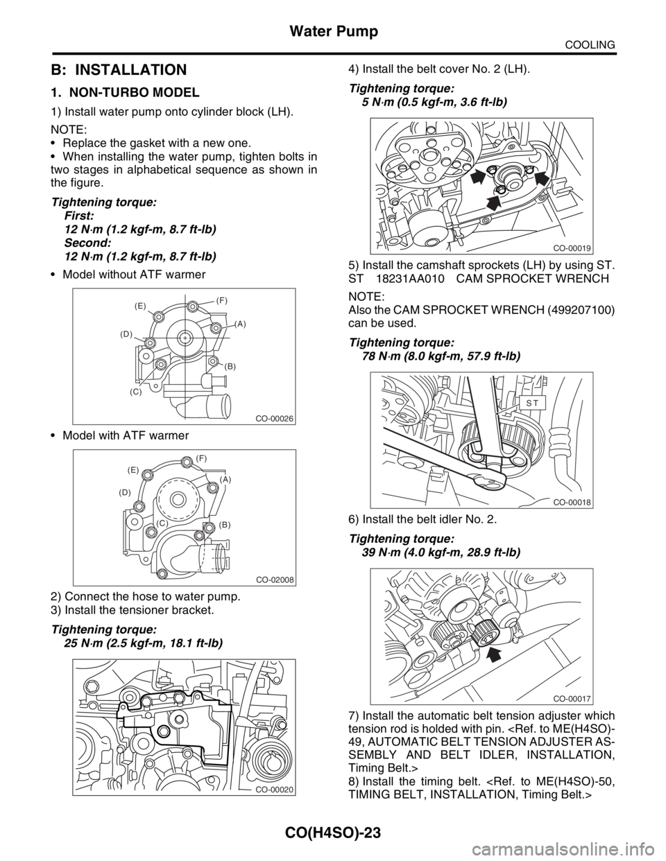
1) Install water pump onto cylinder block (LH).
NOTE:
Replace the gasket with a new one.
When installing the water pump, tighten bolts in
two stages in alphabetical sequence as shown in
the figure.
Tightening torque:
First:
12 N
⋅m (1.2 kgf-m, 8.7 ft-lb)
Second:
12 N
⋅m (1.2 kgf-m, 8.7 ft-lb)
Model without ATF warmer
Model with ATF warmer
2) Connect the hose to water pump.
3) Install the tensioner bracket.
Tightening torque:
25 N
⋅m (2.5 kgf-m, 18.1 ft-lb)4) Install the belt cover No. 2 (LH).
Tightening torque:
5 N
⋅m (0.5 kgf-m, 3.6 ft-lb)
5) Install the camshaft sprockets (LH) by using ST.
ST 18231AA010 CAM SPROCKET WRENCH
NOTE:
Also the CAM SPROCKET WRENCH (499207100)
can be used.
Tightening torque:
78 N
⋅m (8.0 kgf-m, 57.9 ft-lb)
6) Install the belt idler No. 2.
Tightening torque:
39 N
⋅m (4.0 kgf-m, 28.9 ft-lb)
7) Install the automatic belt tension adjuster which
tension rod is holded with pin.
49, AUTOMATIC BELT TENSION ADJUSTER AS-
SEMBLY AND BELT IDLER, INSTALLATION,
Timing Belt.>
8) Install the timing belt.
TIMING BELT, INSTALLATION, Timing Belt.>
CO-00026
(E)
(D)
(B)
(C)(A) (F)
CO-02008
(B) (C) (D)(E)(F)
(A)
CO-00020
CO-00019
CO-00018
ST
CO-00017
Page 1007 of 2870

CO(H4SO)-24
COOLING
Water Pump
9) Install the V-belts.
STALLATION, V-belt.>
10) Install the radiator.
STALLATION, Radiator.>
2. TURBO MODEL
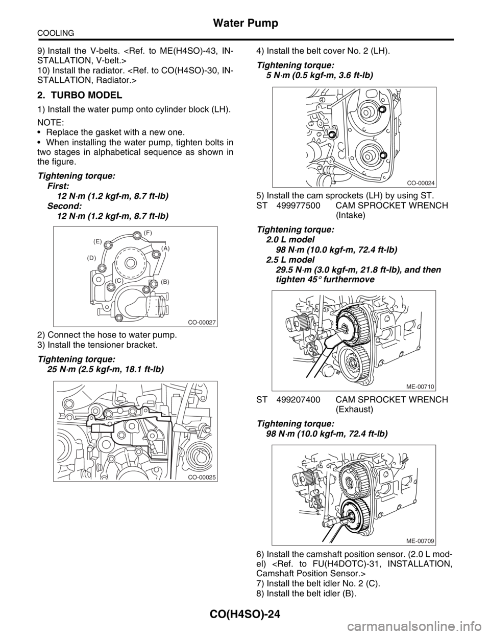
1) Install the water pump onto cylinder block (LH).
NOTE:
Replace the gasket with a new one.
When installing the water pump, tighten bolts in
two stages in alphabetical sequence as shown in
the figure.
Tightening torque:
First:
12 N
⋅m (1.2 kgf-m, 8.7 ft-lb)
Second:
12 N
⋅m (1.2 kgf-m, 8.7 ft-lb)
2) Connect the hose to water pump.
3) Install the tensioner bracket.
Tightening torque:
25 N
⋅m (2.5 kgf-m, 18.1 ft-lb)4) Install the belt cover No. 2 (LH).
Tightening torque:
5 N
⋅m (0.5 kgf-m, 3.6 ft-lb)
5) Install the cam sprockets (LH) by using ST.
ST 499977500 CAM SPROCKET WRENCH
(Intake)
Tightening torque:
2.0 L model
98 N
⋅m (10.0 kgf-m, 72.4 ft-lb)
2.5 L model
29.5 N
⋅m (3.0 kgf-m, 21.8 ft-lb), and then
tighten 45
° furthermove
ST 499207400 CAM SPROCKET WRENCH
(Exhaust)
Tightening torque:
98 N
⋅m (10.0 kgf-m, 72.4 ft-lb)
6) Install the camshaft position sensor. (2.0 L mod-
el)
Camshaft Position Sensor.>
7) Install the belt idler No. 2 (C).
8) Install the belt idler (B).
CO-00027
(B) (C) (D)(E)(F)
(A)
CO-00025
CO-00024
ME-00710
ME-00709
Page 1242 of 2870

EN(H4SO)-144
ENGINE (DIAGNOSTIC)
Diagnostic Procedure with Diagnostic Trouble Code (DTC)
6 CHECK POWER SUPPLY LINE.
1) Turn the ignition switch to ON.
2) Measure the voltage between fuel injector
and engine ground on faulty cylinders.
Connector & terminal
#1 (E5) No. 2 (+) — Engine ground (
−):
#2 (E16) No. 2 (+) — Engine ground (
−):
#3 (E6) No. 2 (+) — Engine ground (
−):
#4 (E17) No. 2 (+) — Engine ground (
−):Is the voltage more than 10 V? Repair poor con-
tact in all connec-
tors in fuel injector
circuit.Repair harness
and connector.
N
OTE:
In this case repair
the following:
Open circuit in
harness between
main relay and fuel
injector connector
on faulty cylinders
Poor contact in
coupling connector
Poor contact in
main relay connec-
tor
Poor contact in
fuel injector con-
nector on faulty
cylinders
7 CHECK HARNESS BETWEEN FUEL INJEC-
TOR AND ECM CONNECTOR.
1) Turn the ignition switch to OFF.
2) Disconnect the connector from fuel injector
on faulty cylinder.
3) Turn the ignition switch to ON.
4) Measure the voltage between ECM con-
nector and chassis ground on faulty cylinders.
Connector & terminal
#1 (B134) No. 34 (+) — Chassis ground (
−):
#2 (B134) No. 23 (+) — Chassis ground (
−):
#3 (B134) No. 22 (+) — Chassis ground (
−):
#4 (B134) No. 8 (+) — Chassis ground (
−):Is the voltage more than 10 V? Repair battery
short circuit in har-
ness between
ECM and fuel
injector. After
repair, replace the
ECM.
FU(H4SO)-44,
Engine Control
Module (ECM).>Go to step 8.
8 CHECK FUEL INJECTOR.
1) Turn the ignition switch to OFF.
2) Measure the resistance between fuel injec-
tor terminals on faulty cylinder.
Te r m i n a l s
No. 1 — No. 2:Is the resistance less than 1
Ω?Replace the faulty
fuel injector
to FU(H4SO)-35,
Fuel Injector.> and
ECM.
FU(H4SO)-44,
Engine Control
Module (ECM).>Go to step 9.
9 CHECK INSTALLATION OF CAMSHAFT PO-
SITION SENSOR/CRANKSHAFT POSITION
SENSOR.Is the installation of camshaft
position sensor or crankshaft
position sensor loosened?Tighten camshaft
position sensor or
crankshaft posi-
tion sensor.Go to step 10.
10 CHECK CRANK SPROCKET.
Remove the timing belt cover.Is the crank sprocket rusted or
does it have broken teeth?Replace the crank
sprocket.
ME(H4SO)-55,
Crank Sprocket.>Go to step 11.
11 CHECK INSTALLATION CONDITION OF
TIMING BELT.
Turn the crankshaft using ST, and align align-
ment mark on crank sprocket with alignment
mark on cylinder block.
ST 499987500 CRANKSHAFT SOCKETIs the timing belt dislocated
from its proper position?Repair installation
condition of timing
belt.
ME(H4SO)-48,
Timing Belt.>Go to step 12.
12 CHECK FUEL LEVEL.Is the fuel meter indication
higher than the “Lower” level?Go to step 13.Replenish fuel so
fuel meter indica-
tion is higher than
the “Lower” level.
After replenishing
fuel, Go to step 13. Step Check Yes No
Page 1258 of 2870
EN(H4SO)-160
ENGINE (DIAGNOSTIC)
Diagnostic Procedure with Diagnostic Trouble Code (DTC)
7 CHECK CONDITION OF CAMSHAFT POSI-
TION SENSOR.
Turn the ignition switch to OFF.Is the camshaft position sensor
installation bolt tightened
securely?Go to step 8.Tighten the cam-
shaft position sen-
sor installation bolt
securely.
8 CHECK CAMSHAFT SPROCKET.
Remove the front belt cover.
ME(H4SO)-47, Timing Belt Cover.>Are cam sprocket teeth
cracked or damaged?Replace the cam
sprocket.
ME(H4SO)-53,
Cam Sprocket.>Go to step 9.
9 CHECK INSTALLATION CONDITION OF
TIMING BELT.
Turn the camshaft using ST, and align align-
ment mark on cam sprocket with alignment
mark on timing belt cover LH.
ST 499207100 CAM SPROCKET WRENCHIs the timing belt dislocated
from its proper position?Repair installation
condition of timing
belt.
ME(H4SO)-48,
Timing Belt.>Replace the cam-
shaft position sen-
sor.
FU(H4SO)-27,
Camshaft Position
Sensor.> Step Check Yes No