Page 901 of 2870
ME(H4SO)-32
MECHANICAL
Valve Clearance
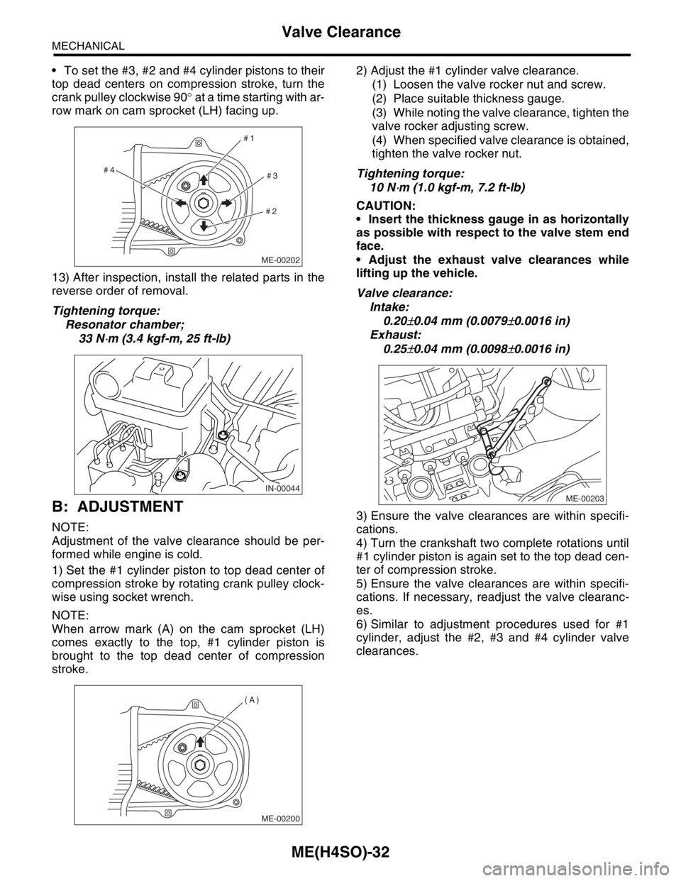
To set the #3, #2 and #4 cylinder pistons to their
top dead centers on compression stroke, turn the
crank pulley clockwise 90° at a time starting with ar-
row mark on cam sprocket (LH) facing up.
13) After inspection, install the related parts in the
reverse order of removal.
Tightening torque:
Resonator chamber;
33 N
⋅m (3.4 kgf-m, 25 ft-lb)
B: ADJUSTMENT
NOTE:
Adjustment of the valve clearance should be per-
formed while engine is cold.
1) Set the #1 cylinder piston to top dead center of
compression stroke by rotating crank pulley clock-
wise using socket wrench.
NOTE:
When arrow mark (A) on the cam sprocket (LH)
comes exactly to the top, #1 cylinder piston is
brought to the top dead center of compression
stroke.2) Adjust the #1 cylinder valve clearance.
(1) Loosen the valve rocker nut and screw.
(2) Place suitable thickness gauge.
(3) While noting the valve clearance, tighten the
valve rocker adjusting screw.
(4) When specified valve clearance is obtained,
tighten the valve rocker nut.
Tightening torque:
10 N
⋅m (1.0 kgf-m, 7.2 ft-lb)
CAUTION:
Insert the thickness gauge in as horizontally
as possible with respect to the valve stem end
face.
Adjust the exhaust valve clearances while
lifting up the vehicle.
Valve clearance:
Intake:
0.20
±0.04 mm (0.0079±0.0016 in)
Exhaust:
0.25
±0.04 mm (0.0098±0.0016 in)
3) Ensure the valve clearances are within specifi-
cations.
4) Turn the crankshaft two complete rotations until
#1 cylinder piston is again set to the top dead cen-
ter of compression stroke.
5) Ensure the valve clearances are within specifi-
cations. If necessary, readjust the valve clearanc-
es.
6) Similar to adjustment procedures used for #1
cylinder, adjust the #2, #3 and #4 cylinder valve
clearances.
ME-00202
#1
#2#3 #4
IN-00044
ME-00200
(A)
ME-00203
Page 902 of 2870
ME(H4SO)-33
MECHANICAL
Valve Clearance
NOTE:
Be sure to set the cylinder pistons to their re-
spective top dead centers on compression stroke
before adjusting valve clearances.
To set the #3, #2 and #4 cylinder pistons to their
top dead centers of compression stroke, turn the
crank pulley clockwise 90° at a time starting with ar-
row mark on cam sprocket (LH) facing up.
ME-00202
#1
#2#3 #4
Page 917 of 2870
ME(H4SO)-48
MECHANICAL
Timing Belt
15.Timing Belt
A: REMOVAL
1. TIMING BELT
1) Remove the V-belt.
MOVAL, V-belt.>
2) Remove the crank pulley.
45, REMOVAL, Crank Pulley.>
3) Remove the belt cover.
REMOVAL, Timing Belt Cover.>
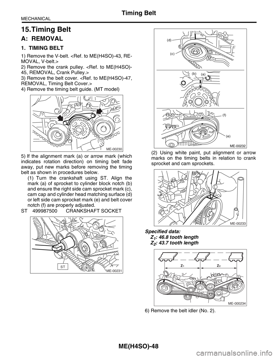
4) Remove the timing belt guide. (MT model)
5) If the alignment mark (a) or arrow mark (which
indicates rotation direction) on timing belt fade
away, put new marks before removing the timing
belt as shown in procedures below.
(1) Turn the crankshaft using ST. Align the
mark (a) of sprocket to cylinder block notch (b)
and ensure the right side cam sprocket mark (c),
cam cap and cylinder head matching surface (d)
or left side cam sprocket mark (e) and belt cover
notch (f) are properly adjusted.
ST 499987500 CRANKSHAFT SOCKET(2) Using white paint, put alignment or arrow
marks on the timing belts in relation to crank
sprocket and cam sprockets.
Specified data:
Z
1: 46.8 tooth length
Z
2: 43.7 tooth length
6) Remove the belt idler (No. 2).
ME-00230
ME-00231ST
ME-00232
(a) (b) (d)
(c)
(f)
(e)
ME-00233
ME-000234
Z1Z2
Page 919 of 2870
ME(H4SO)-50
MECHANICAL
Timing Belt
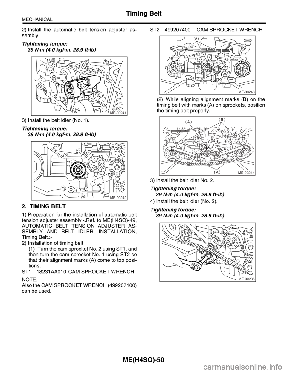
2) Install the automatic belt tension adjuster as-
sembly.
Tightening torque:
39 N
⋅m (4.0 kgf-m, 28.9 ft-lb)
3) Install the belt idler (No. 1).
Tightening torque:
39 N
⋅m (4.0 kgf-m, 28.9 ft-lb)
2. TIMING BELT
1) Preparation for the installation of automatic belt
tension adjuster assembly
AUTOMATIC BELT TENSION ADJUSTER AS-
SEMBLY AND BELT IDLER, INSTALLATION,
Timing Belt.>
2) Installation of timing belt
(1) Turn the cam sprocket No. 2 using ST1, and
then turn the cam sprocket No. 1 using ST2 so
that their alignment marks (A) come to top posi-
tions.
ST1 18231AA010 CAM SPROCKET WRENCH
NOTE:
Also the CAM SPROCKET WRENCH (499207100)
can be used.ST2 499207400 CAM SPROCKET WRENCH
(2) While aligning alignment marks (B) on the
timing belt with marks (A) on sprockets, position
the timing belt properly.
3) Install the belt idler No. 2.
Tightening torque:
39 N
⋅m (4.0 kgf-m, 28.9 ft-lb)
4) Install the belt idler (No. 2).
Tightening torque:
39 N
⋅m (4.0 kgf-m, 28.9 ft-lb)
ME-00241
ME-00242
ME-00243
(A)
ME-00244
ME-00235
Page 920 of 2870
ME(H4SO)-51
MECHANICAL
Timing Belt
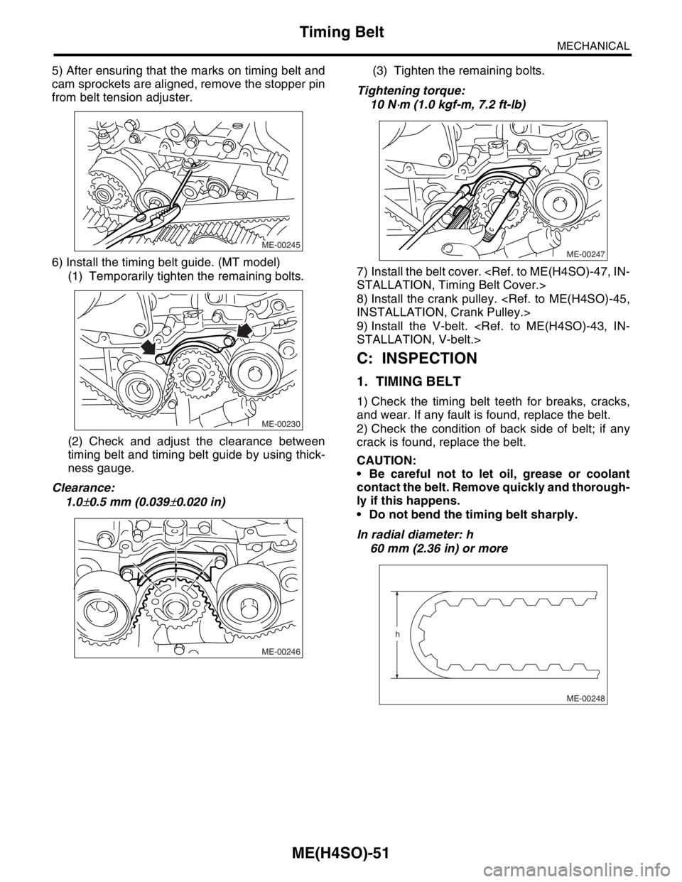
5) After ensuring that the marks on timing belt and
cam sprockets are aligned, remove the stopper pin
from belt tension adjuster.
6) Install the timing belt guide. (MT model)
(1) Temporarily tighten the remaining bolts.
(2) Check and adjust the clearance between
timing belt and timing belt guide by using thick-
ness gauge.
Clearance:
1.0
±0.5 mm (0.039±0.020 in)(3) Tighten the remaining bolts.
Tightening torque:
10 N
⋅m (1.0 kgf-m, 7.2 ft-lb)
7) Install the belt cover.
STALLATION, Timing Belt Cover.>
8) Install the crank pulley.
INSTALLATION, Crank Pulley.>
9) Install the V-belt.
STALLATION, V-belt.>
C: INSPECTION
1. TIMING BELT
1) Check the timing belt teeth for breaks, cracks,
and wear. If any fault is found, replace the belt.
2) Check the condition of back side of belt; if any
crack is found, replace the belt.
CAUTION:
Be careful not to let oil, grease or coolant
contact the belt. Remove quickly and thorough-
ly if this happens.
Do not bend the timing belt sharply.
In radial diameter: h
60 mm (2.36 in) or more
ME-00245
ME-00230
ME-00246
ME-00247
ME-00248
h
Page 923 of 2870

MECHANICAL
ME(H4SO)
Page
1. General Description ....................................................................................2
2. Compression .............................................................................................25
3. Idle Speed .................................................................................................26
4. Ignition Timing ...........................................................................................27
5. Intake Manifold Vacuum............................................................................28
6. Engine Oil Pressure ..................................................................................29
7. Fuel Pressure ............................................................................................30
8. Valve Clearance ........................................................................................31
9. Engine Assembly ......................................................................................34
10. Engine Mounting .......................................................................................41
11. Preparation for Overhaul ...........................................................................42
12. V-belt .........................................................................................................43
13. Crank Pulley ..............................................................................................45
14. Timing Belt Cover......................................................................................47
15. Timing Belt ................................................................................................48
16. Cam Sprocket ...........................................................................................53
17. Crank Sprocket .........................................................................................55
18. Valve Rocker Assembly ............................................................................56
19. Camshaft ...................................................................................................58
20. Cylinder Head ...........................................................................................62
21. Cylinder Block ...........................................................................................69
22. Engine Trouble in General ........................................................................91
23. Engine Noise .............................................................................................96
Page 924 of 2870
ME(H4SO)-53
MECHANICAL
Cam Sprocket
16.Cam Sprocket
A: REMOVAL
1. REMOVAL
1) Remove the V-belt.
MOVAL, V-belt.>
2) Remove the crank pulley.
45, REMOVAL, Crank Pulley.>
3) Remove the belt cover.
REMOVAL, Timing Belt Cover.>
4) Remove the timing belt assembly.
ME(H4SO)-48, REMOVAL, Timing Belt.>
5) Remove the camshaft position sensor.
FU(H4SO)-27, REMOVAL, Camshaft Position
Sensor.>
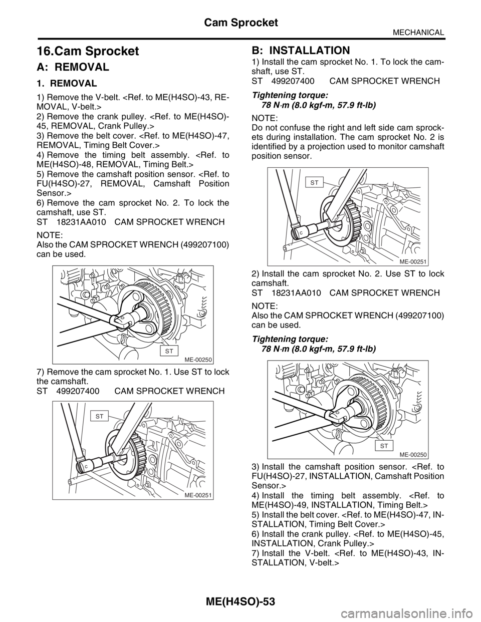
6) Remove the cam sprocket No. 2. To lock the
camshaft, use ST.
ST 18231AA010 CAM SPROCKET WRENCH
NOTE:
Also the CAM SPROCKET WRENCH (499207100)
can be used.
7) Remove the cam sprocket No. 1. Use ST to lock
the camshaft.
ST 499207400 CAM SPROCKET WRENCH
B: INSTALLATION
1) Install the cam sprocket No. 1. To lock the cam-
shaft, use ST.
ST 499207400 CAM SPROCKET WRENCH
Tightening torque:
78 N
⋅m (8.0 kgf-m, 57.9 ft-lb)
NOTE:
Do not confuse the right and left side cam sprock-
ets during installation. The cam sprocket No. 2 is
identified by a projection used to monitor camshaft
position sensor.
2) Install the cam sprocket No. 2. Use ST to lock
camshaft.
ST 18231AA010 CAM SPROCKET WRENCH
NOTE:
Also the CAM SPROCKET WRENCH (499207100)
can be used.
Tightening torque:
78 N
⋅m (8.0 kgf-m, 57.9 ft-lb)
3) Install the camshaft position sensor.
FU(H4SO)-27, INSTALLATION, Camshaft Position
Sensor.>
4) Install the timing belt assembly.
ME(H4SO)-49, INSTALLATION, Timing Belt.>
5) Install the belt cover.
STALLATION, Timing Belt Cover.>
6) Install the crank pulley.
INSTALLATION, Crank Pulley.>
7) Install the V-belt.
STALLATION, V-belt.>
ME-00250
ST
ME-00251
ST
ME-00251
ST
ME-00250
ST
Page 925 of 2870
ME(H4SO)-54
MECHANICAL
Cam Sprocket
C: INSPECTION
1) Check the cam sprocket teeth for abnormal wear
and scratches.
2) Make sure there is no free play between cam
sprocket and key.
3) Check the cam sprocket notch for sensor for
damage and contamination of foreign matter.