2004 SUBARU FORESTER cam sprocket
[x] Cancel search: cam sprocketPage 1542 of 2870

MECHANICAL
ME(H4DOTC)
Page
1. General Description ....................................................................................2
2. Compression .............................................................................................31
3. Idle Speed .................................................................................................32
4. Ignition Timing ...........................................................................................33
5. Intake Manifold Vacuum............................................................................34
6. Engine Oil Pressure ..................................................................................35
7. Fuel Pressure ............................................................................................36
8. Valve Clearance ........................................................................................37
9. Engine Assembly ......................................................................................41
10. Engine Mounting .......................................................................................50
11. Preparation for Overhaul ...........................................................................51
12. V-belt .........................................................................................................52
13. Crank Pulley ..............................................................................................55
14. Timing Belt Cover......................................................................................57
15. Timing Belt Assembly................................................................................58
16. Cam Sprocket ...........................................................................................67
17. Crank Sprocket .........................................................................................68
18. Camshaft ...................................................................................................69
19. Cylinder Head Assembly ...........................................................................76
20. Cylinder Block ...........................................................................................84
21. Intake and Exhaust Valve .......................................................................115
22. Piston ......................................................................................................116
23. Connecting Rod ......................................................................................117
24. Crankshaft ...............................................................................................118
25. Engine Trouble in General ......................................................................119
26. Engine Noise ...........................................................................................124
Page 1543 of 2870

ME(H4DOTC)-83
MECHANICAL
Cylinder Block
20.Cylinder Block
A: REMOVAL
NOTE:
Before conducting this procedure, drain the engine
oil completely if applicable.
1) Remove the intake manifold.
2) Remove the V-belt.
3) Remove the crank pulley.
4) Remove the timing belt cover.
5) Remove the timing belt assembly.
bly.>
6) Remove the cam sprocket.
7) Remove the crank sprocket.
8) Remove the generator and A/C compressor with
their brackets.
9) Remove the cylinder head assembly.
sembly.>
10) Remove the clutch disc and cover. (MT model)
11) Remove the flywheel. (MT model)
12) Remove the drive plate. (AT model)
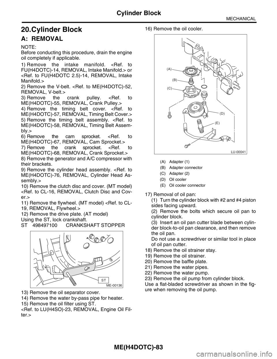
Using the ST, lock crankshaft.
ST 498497100 CRANKSHAFT STOPPER
13) Remove the oil separator cover.
14) Remove the water by-pass pipe for heater.
15) Remove the oil filter using ST.
17) Removal of oil pan:
(1) Turn the cylinder block with #2 and #4 piston
sides facing upward.
(2) Remove the bolts which secure oil pan to
cylinder block.
(3) Insert an oil pan cutter blade between cylin-
der block-to-oil pan clearance, and then remove
the oil pan.
Do not use a screwdriver or similar tool in place
of oil pan cutter.
18) Remove the oil strainer stay.
19) Remove the oil strainer.
20) Remove the baffle plate.
21) Remove the water pipes.
22) Remove the water pump.
23) Remove the oil pump from cylinder block.
Use a flat-bladed screwdriver as shown in the fig-
ure when removing the oil pump.
ME-00136
ST
(A) Adapter (1)
(B) Adapter connector
(C) Adapter (2)
(D) Oil cooler
(E) Oil cooler connector
LU-00041
(A)
(B)
(C)
(D)
(E)
Page 1555 of 2870

ME(H4DOTC)-95
MECHANICAL
Cylinder Block
33) Install the oil filter using ST.
34) Install the water by-pass pipe between oil cool-
er and water pump.
35) Install the water pipe.
NOTE:
Always use a new O-ring.
36) Install the cylinder head assembly.
Assembly.>
37) Install the oil level gauge guide and tighten the
attaching bolt (LH side).
38) Install the rocker cover.
39) Install the crank sprocket.
et.>40) Install the cam sprocket.
et.>
41) Install the timing belt assembly.
Assembly.>
42) Install the timing belt cover.
Cover.>
43) Install the crank pulley.
44) Install the generator and A/C compressor
brackets on cylinder head.
45) Install the V-belt.
46) Install the intake manifold.
fold.>
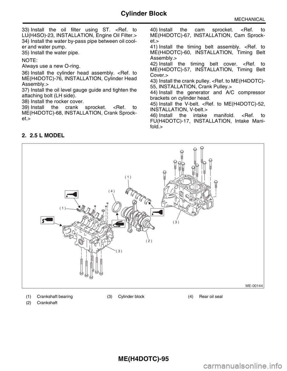
2. 2.5 L MODEL
(1) Crankshaft bearing (3) Cylinder block (4) Rear oil seal
(2) Crankshaft
ME-00144
( 1 )
( 1 )
( 2 )
( 3 )
( 3 )
( 4 )
Page 1563 of 2870

ME(H4DOTC)-103
MECHANICAL
Cylinder Block
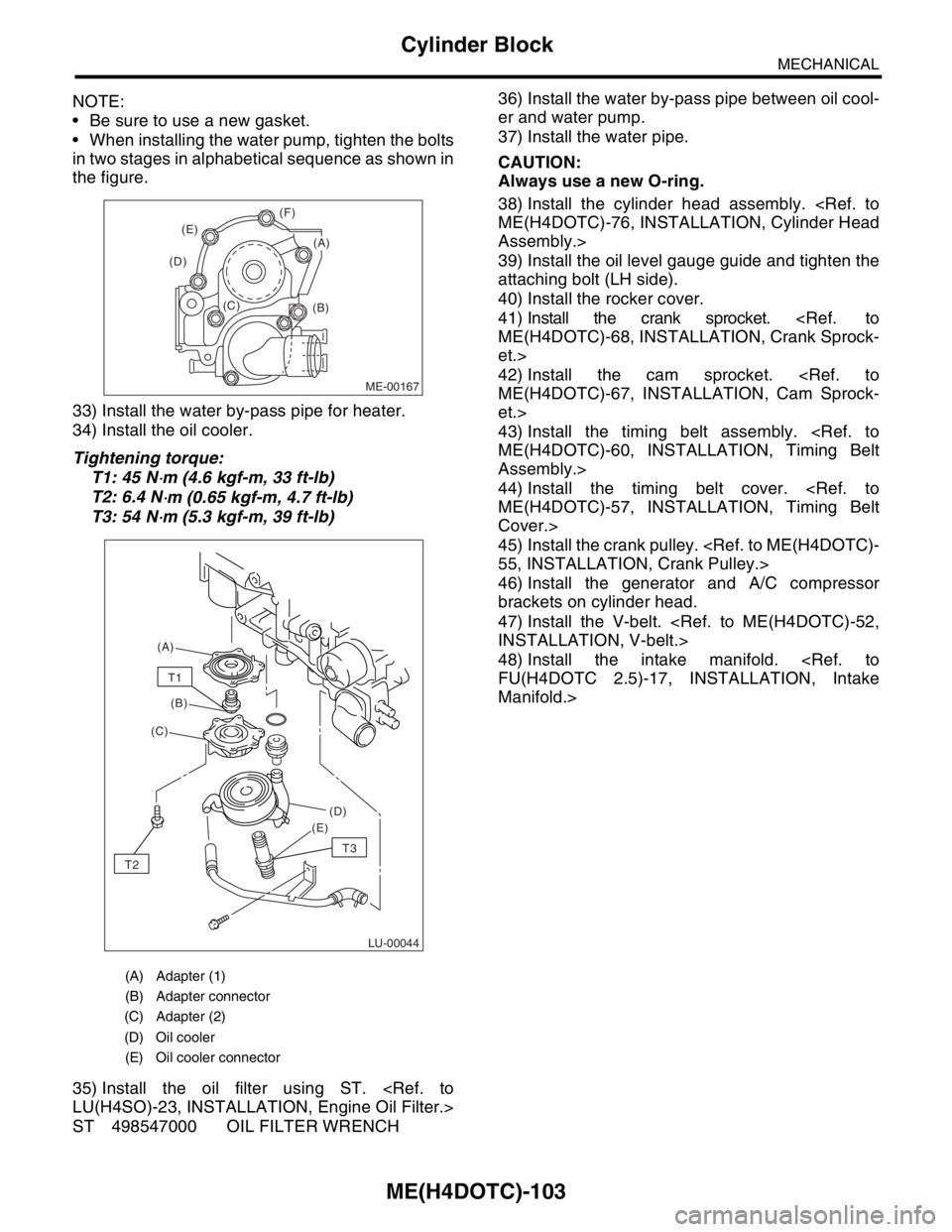
NOTE:
Be sure to use a new gasket.
When installing the water pump, tighten the bolts
in two stages in alphabetical sequence as shown in
the figure.
33) Install the water by-pass pipe for heater.
34) Install the oil cooler.
Tightening torque:
T1: 45 N
⋅m (4.6 kgf-m, 33 ft-lb)
T2: 6.4 N
⋅m (0.65 kgf-m, 4.7 ft-lb)
T3: 54 N
⋅m (5.3 kgf-m, 39 ft-lb)
35) Install the oil filter using ST.
ST 498547000 OIL FILTER WRENCH36) Install the water by-pass pipe between oil cool-
er and water pump.
37) Install the water pipe.
CAUTION:
Always use a new O-ring.
38) Install the cylinder head assembly.
Assembly.>
39) Install the oil level gauge guide and tighten the
attaching bolt (LH side).
40) Install the rocker cover.
41) Install the crank sprocket.
et.>
42) Install the cam sprocket.
et.>
43) Install the timing belt assembly.
Assembly.>
44) Install the timing belt cover.
Cover.>
45) Install the crank pulley.
46) Install the generator and A/C compressor
brackets on cylinder head.
47) Install the V-belt.
48) Install the intake manifold.
Manifold.>
(A) Adapter (1)
(B) Adapter connector
(C) Adapter (2)
(D) Oil cooler
(E) Oil cooler connector
ME-00167
(B) (C) (D)(E)(F)
(A)
LU-00044
(A)
(B)
(C)
(D)
(E)
T1
T2
T3
Page 1800 of 2870

EN(H4DOTC)-167
ENGINE (DIAGNOSTIC)
Diagnostic Procedure with Diagnostic Trouble Code (DTC)
6 CHECK POWER SUPPLY LINE.
1) Turn the ignition switch to ON.
2) Measure the voltage between fuel injector
and engine ground on faulty cylinders.
Connector & terminal
#1 (E5) No. 2 (+) — Engine ground (
−):
#2 (E16) No. 2 (+) — Engine ground (
−):
#3 (E6) No. 2 (+) — Engine ground (
−):
#4 (E17) No. 2 (+) — Engine ground (
−):Is the voltage more than 10 V? Repair poor con-
tact in all connec-
tors in fuel injector
circuit.Repair the har-
ness and connec-
tor.
N
OTE:
In this case repair
the following:
Open circuit in
harness between
main relay and fuel
injector connector
on faulty cylinders
Poor contact in
coupling connector
Poor contact in
main relay connec-
tor
Poor contact in
fuel injector con-
nector on faulty
cylinders
7 CHECK HARNESS BETWEEN FUEL INJEC-
TOR AND ECM CONNECTOR.
1) Turn the ignition switch to OFF.
2) Disconnect the connector from fuel injector
on faulty cylinder.
3) Turn the ignition switch to ON.
4) Measure the voltage between ECM con-
nector and chassis ground on faulty cylinders.
Connector & terminal
#1 (B136) No. 6 (+) — Chassis ground (
−):
#2 (B136 No. 5 (+) — Chassis ground (
−):
#3 (B136 No. 4 (+) — Chassis ground (
−):
#4 (B136 No. 3 (+) — Chassis ground (
−):Is the voltage more than 10 V? Repair battery
short circuit in har-
ness between
ECM and fuel
injector.After
repair, replace the
ECM.
Engine Control
Module (ECM).>Go to step 8.
8 CHECK FUEL INJECTOR.
1) Turn the ignition switch to OFF.
2) Measure the resistance between fuel injec-
tor terminals on faulty cylinder.
Te r m i n a l s
No. 1 — No. 2:Is the resistance less than 1
Ω?Replace the faulty
fuel injector and
ECM.
Fuel Injector.>
Engine Control
Module (ECM).>Go to step 9.
9 CHECK INSTALLATION OF CAMSHAFT PO-
SITION SENSOR/CRANKSHAFT POSITION
SENSOR.Is the installation of camshaft
position sensor or crankshaft
position sensor loosened?Tighten camshaft
position sensor or
crankshaft posi-
tion sensor.Go to step 10.
10 CHECK CRANK SPROCKET.
Remove the timing belt cover.Is the crank sprocket rusted or
does it have broken teeth?Replace the crank
sprocket.
Crank Sprocket.>Go to step 11.
11 CHECK INSTALLATION CONDITION OF
TIMING BELT.
Turn the crankshaft, and align alignment mark
on crank sprocket with alignment mark on cyl-
inder block.Is the timing belt dislocated
from its proper position?Repair installation
condition of timing
belt.
Timing Belt
Assembly.>Go to step 12. Step Check Yes No
Page 1814 of 2870

EN(H4DOTC)-181
ENGINE (DIAGNOSTIC)
Diagnostic Procedure with Diagnostic Trouble Code (DTC)
5 CHECK CONDITION OF CAMSHAFT POSI-
TION SENSOR CONNECTOR.Is the camshaft position sensor
connector installation bolt tight-
ened securely?Go to step 6.Tighten the cam-
shaft position sen-
sor connector
installation bolt
securely.
6 CHECK CAMSHAFT POSITION SENSOR
CONNECTOR.
1) Remove the camshaft position sensor con-
nector.
2) Measure the resistance between connector
terminals of camshaft position sensor connec-
tor.
Te r m i n a l s
No. 1 — No. 2:Is the resistance 1 — 4 kΩ? Go to step 7.Replace the cam-
shaft position sen-
sor connector.
Camshaft Position
Sensor.>
7 CHECK CONDITION OF CAMSHAFT POSI-
TION SENSOR CONNECTOR.
Turn the ignition switch to OFF.Is the camshaft position sensor
connector installation bolt tight-
ened securely?Go to step 8.Tighten the cam-
shaft position sen-
sor connector
installation bolt
securely.
8 CHECK CAM SPROCKET.
Remove the front belt cover.
cracked or damaged?Replace the cam
sprocket.
Cam Sprocket.>Go to step 9.
9 CHECK INSTALLATION CONDITION OF
TIMING BELT.
Turn the crankshaft, and align alignment mark
on camshaft sprocket with alignment mark on
timing belt cover LH.Is the timing belt dislocated
from its proper position?Repair installation
condition of timing
belt.
Timing Belt
Assembly.>Replace the cam-
shaft position sen-
sor connector.
Camshaft Position
Sensor.> Step Check Yes No