2004 SUBARU FORESTER engine
[x] Cancel search: enginePage 389 of 2870

IDI-5
INSTRUMENTATION/DRIVER INFO
Combination Meter System
2. CHECK POWER SUPPLY AND GROUND CIRCUIT
3. CHECK VEHICLE SPEED SENSOR
Step Check Yes No
1 CHECK POWER SUPPLY FOR COMBINA-
TION METER.
1) Remove the combination meter.
Assembly.>
2) Disconnect the combination meter harness
connector.
3) Turn the ignition switch to ON.
4) Measure the voltage between combination
meter connector and chassis ground.
Connector & terminal
(i10) No. 9 (+) — Chassis ground (
−):Is the voltage more than 10 V? Go to step 2.Check the harness
for open or short
between ignition
switch and combi-
nation meter.
2 CHECK POWER SUPPLY FOR COMBINA-
TION METER.
Measure the voltage between combination
meter connector and chassis ground.
Connector & terminal
(i10) No. 8 (+) — Chassis ground (
−):Is the voltage more than 10 V? Go to step 3.Check the harness
for open or short
between fuse and
combination
meter.
3 CHECK GROUND CIRCUIT OF COMBINA-
TION METER.
1) Turn the ignition switch to OFF.
2) Measure the resistance of harness
between combination meter connector and
chassis ground.
Connector & terminal
(i10) No. 10 — Chassis ground:Is the resistance less than 10
Ω?Replace the com-
bination meter
printed circuit.Repair the wiring
harness.
Step Check Yes No
1 CHECK VEHICLE SPEED SENSOR.
1) Lift-up the vehicle and support it with rigid
racks.
2) Remove the combination meter with har-
ness connector.
3) Drive the vehicle at a speed greater than 20
km/h (12 MPH).
Warning:
Be careful not to get caught in the running
wheels.
4) Measure the voltage between combination
meter connector and chassis ground.
Connector & terminal
(i10) No. 12 (+) — Chassis ground (
−):Is the voltage 1 V ← → 5 V? Check the speed-
ometer.
TION, Speedome-
ter.>Go to step 2.
2 CHECK VEHICLE SPEED SENSOR POWER
SUPPLY.
1) Turn the ignition switch to OFF.
2) Disconnect the vehicle speed sensor har-
ness connector.
3) Turn the ignition switch to ON.
4) Measure the voltage between vehicle
speed sensor connector and engine ground.
Connector & terminal
(B17) No. 3 (+) — Engine ground (
−):Is the voltage more than 10 V? Go to step 3.Check the harness
for open or short
between ignition
switch and vehicle
speed sensor.
Page 390 of 2870

IDI-6
INSTRUMENTATION/DRIVER INFO
Combination Meter System
4. CHECK TRANSMISSION CONTROL MODULE (TCM)
3 CHECK HARNESS BETWEEN VEHICLE
SPEED SENSOR AND ENGINE GROUND.
1) Turn the ignition switch to OFF.
2) Measure the resistance between vehicle
speed sensor connector and engine ground.
Connector & terminal
(B17) No. 2 — Engine ground:Is the resistance less than 10
Ω?Go to step 4.Repair the wiring
harness.
4 CHECK HARNESS BETWEEN VEHICLE
SPEED SENSOR AND COMBINATION
METER.
1) Disconnect the connector from combination
meter.
2) Measure the resistance between vehicle
speed sensor harness connector and combi-
nation meter harness connector.
Connector & terminal
(B17) No. 1 — (i10) No. 12:Is the resistance less than 10
Ω?Replace the vehi-
cle speed sensor.Repair the wiring
harness.
Step Check Yes No
1 CHECK TCM SIGNAL.
1) Lift-up the vehicle and support it with rigid
racks.
2) Drive the vehicle faster than 10 km/h (6
MPH).
Warning:
Be careful not to get caught in the running
wheels.
3) Measure the voltage between TCM con-
nector and chassis ground.
Connector & terminal
(B56) No. 17 (+) — Chassis ground (
−):Is the voltage 1 V ← → 5 V? Go to step 2.Check TCM.
Basic Diagnostic
Procedure.>
2 CHECK HARNESS BETWEEN TCM AND
COMBINATION METER.
1) Turn the ignition switch to OFF.
2) Disconnect the connector from TCM and
combination meter.
3) Measure the resistance between TCM har-
ness connector and combination meter har-
ness connector.
Connector & terminal
(B56) No. 17 — (i10) No. 12:Is the resistance less than 10
Ω?Check the speedo
meter.
Speedometer.>Repair the wiring
harness. Step Check Yes No
Page 391 of 2870

IDI-7
INSTRUMENTATION/DRIVER INFO
Combination Meter System
5. CHECK ENGINE CONTROL MODULE (ECM)
6. CHECK FUEL LEVEL SENSOR
Step Check Yes No
1 CHECK ECM SIGNAL.
1) Start the engine.
2) Measure the voltage between ECM con-
nector and engine ground.
Connector & terminal
Non-turbo model
(B134) No. 10 (+) — Engine ground (
−):
Turbo model
(B134) No. 23 (+) — Engine ground (
−):Is the voltage 0 V ← → 14 V? Go to step 2.Check ECM.
Basic Diagnostics
Procedure.>
Basic Diagnostics
Procedure.>
2 CHECK HARNESS BETWEEN COMBINA-
TION METER AND ECM.
1) Turn the ignition switch to OFF.
2) Disconnect the connector from ECM and
combination meter.
3) Measure the resistance between ECM har-
ness connector and combination meter har-
ness connector.
Connector & terminal
Non-turbo model
(B134) No. 10 — (i10) No. 11:
Turbo model
(B134) No. 23 — (i10) No. 11:Is the resistance less than 10
Ω?Check the tachom-
eter.
Tachometer.>Repair the wiring
harness.
Step Check Yes No
1 CHECK FUEL LEVEL SENSOR.
1) Remove the fuel level sensor.
sor.>
2) Measure the resistance between fuel level
sensor terminals when setting the float to
FULL and EMPTY position.
Te r m i n a l s
No. 3 — No. 5:Is the resistance 0.5 to 2.5 Ω
(FULL) and 50 to 52 Ω
(EMPTY)?Go to step 2.Replace the fuel
level sensor.
2 CHECK FUEL SUB LEVEL SENSOR.
1) Remove the fuel sub level sensor.
Sensor.>
2) Measure the resistance between fuel sub
level sensor terminals when setting the float to
FULL and EMPTY position.
Te r m i n a l s
No. 1 — No. 2:Is the resistance 0.5 to 2.5 Ω
(FULL) and 42 to 44 Ω
(EMPTY)?Go to step 3.Replace the fuel
sub level sensor.
3 CHECK HARNESS BETWEEN FUEL SUB
LEVEL SENSOR AND COMBINATION
METER.
1) Disconnect the connector from combination
meter.
2) Measure the resistance between fuel sub
level sensor harness connector terminal and
combination meter harness connector termi-
nal.
Connector & terminal
(R59) No. 1 — (i11) No. 1:Is the resistance less than 10
Ω?Go to step 4.Repair the wiring
harness.
Page 392 of 2870

IDI-8
INSTRUMENTATION/DRIVER INFO
Combination Meter System
7. CHECK ENGINE COOLANT TEMPERATURE SENSOR
8. CHECK OUTSIDE TEMPERATURE INDICATOR
4 CHECK HARNESS BETWEEN FUEL LEVEL
SENSOR AND FUEL SUB LEVEL SENSOR.
Measure the resistance between fuel level sen-
sor harness connector terminal and fuel sub
level sensor harness connector terminal.
Connector & terminal
(R58) No. 3 — (R59) No. 2:Is the resistance less than 10
Ω?Go to step 5.Repair the wiring
harness.
5 CHECK FUEL LEVEL SENSOR GROUND
CIRCUIT.
Measure the resistance between fuel level sen-
sor harness connector terminal and chassis
ground.
Connector & terminal
(R58) No. 5 — Chassis ground:Is the resistance less than 10
Ω?Check the fuel
gauge.
TION, Fuel
Gauge.>Repair the wiring
harness.
Step Check Yes No
1 CHECK ENGINE COOLANT TEMPERATURE
SENSOR.
Check the engine coolant temperature sensor.
ture sensor OK?Go to step 2.Replace the
engine coolant
temperature sen-
sor.
2 CHECK HARNESS BETWEEN ENGINE
COOLANT TEMPERATURE SENSOR AND
COMBINATION METER.
1) Turn the ignition switch to OFF.
2) Disconnect the connector from engine cool-
ant temperature sensor and combination
meter.
3) Measure the resistance between engine
coolant temperature sensor harness connector
and combination meter harness connector.
Connector & terminal
(E8) No. 3 — (i11) No. 10:Is the resistance less than 10
Ω?Go to step 3.Repair the wiring
harness.
3 CHECK WATER TEMPERATURE GAUGE
GROUND CIRCUIT.
Measure the resistance between combination
meter harness connector terminal and chassis
ground.
Connector & terminal
(i11) No. 9 — Chassis ground:Is the resistance less than 10
Ω?Check the water
temperature
gauge.
TION, Water Tem-
perature Gauge.>Repair the wiring
harness.
Step Check Yes No
1 CHECK POWER SUPPLY FOR AMBIENT
SENSOR.
1) Turn the ignition switch to OFF.
2) Disconnect the connector from outside
temperature sensor.
3) Turn the ignition switch to ON.
4) Measure the voltage between outside tem-
perature sensor harness connector terminal
and chassis ground.
Connector & terminal
(F78) No. 2 (+) — Chassis ground (
−):Is the voltage more than 4 V? Go to step 3.Go to step 2. Step Check Yes No
Page 555 of 2870

CC-3
CRUISE CONTROL SYSTEM
General Description
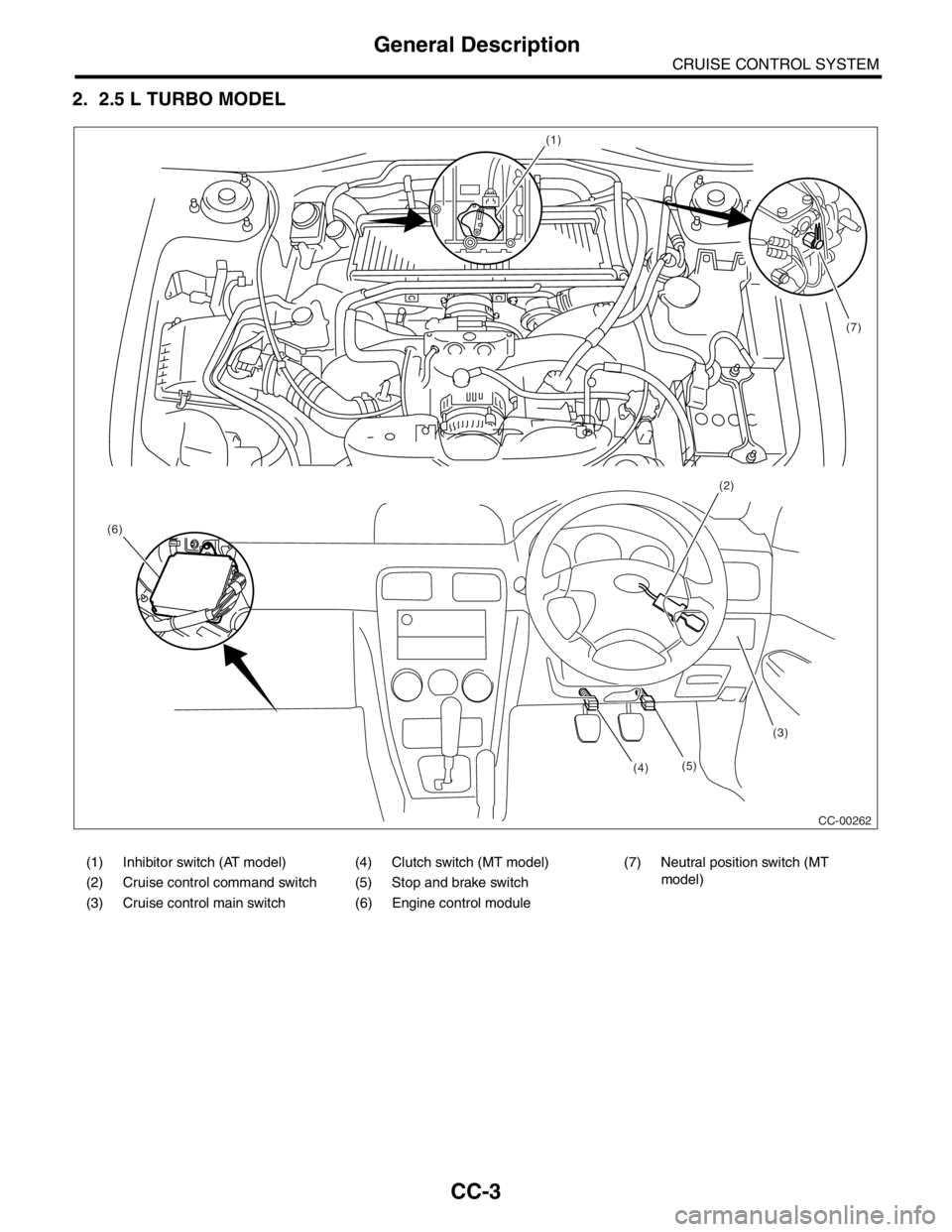
2. 2.5 L TURBO MODEL
(1)
(2)
(3)
(4) (6)(7)
CC-00262 (5)
(1) Inhibitor switch (AT model) (4) Clutch switch (MT model) (7) Neutral position switch (MT
model)
(2) Cruise control command switch (5) Stop and brake switch
(3) Cruise control main switch (6) Engine control module
Page 559 of 2870

CC-7
CRUISE CONTROL SYSTEM
Cruise Control Module
3. Cruise Control Module
A: NOTE
Engine Control Module (ECM) controls cruise con-
trol system (Turbo model).
B: REMOVAL
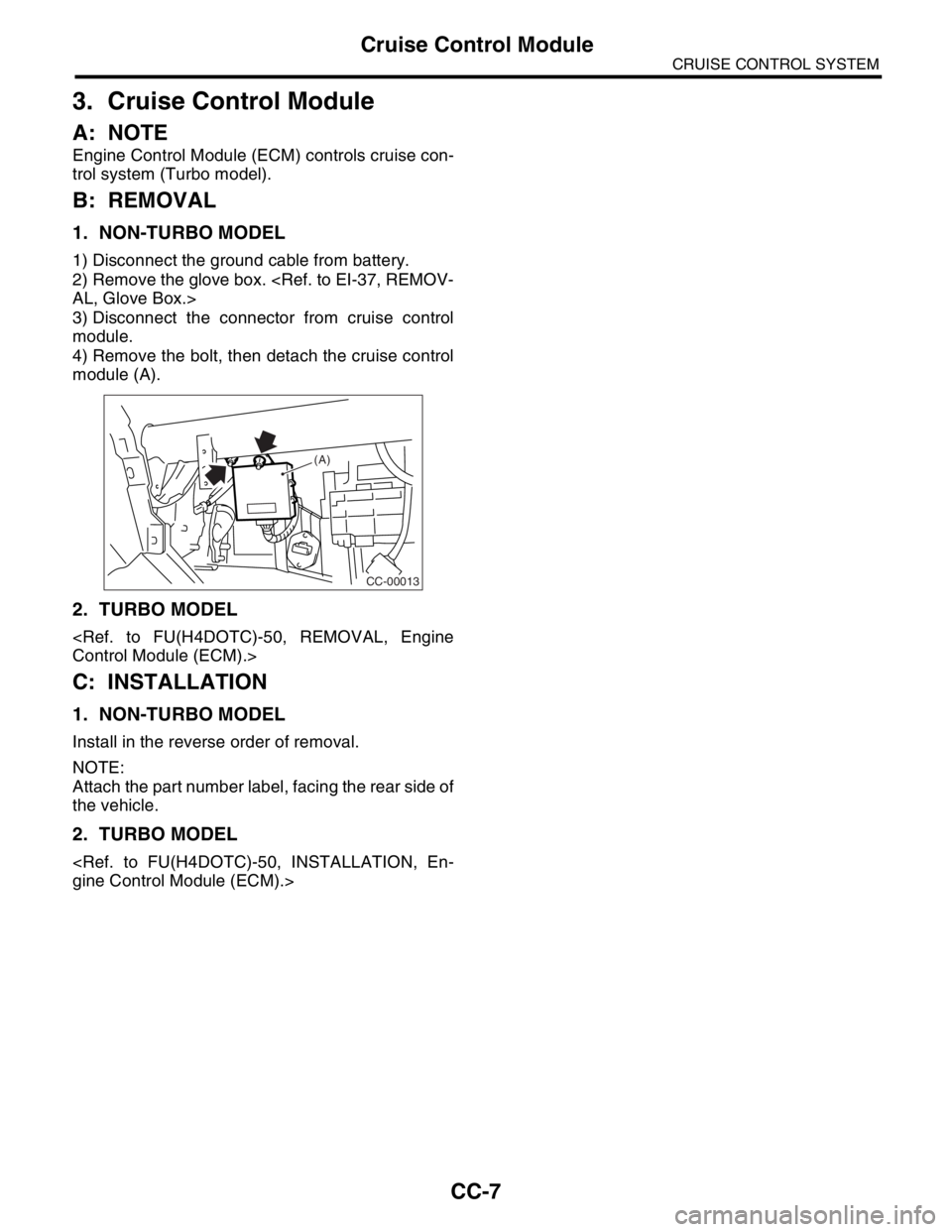
1. NON-TURBO MODEL
1) Disconnect the ground cable from battery.
2) Remove the glove box.
3) Disconnect the connector from cruise control
module.
4) Remove the bolt, then detach the cruise control
module (A).
2. TURBO MODEL
C: INSTALLATION
1. NON-TURBO MODEL
Install in the reverse order of removal.
NOTE:
Attach the part number label, facing the rear side of
the vehicle.
2. TURBO MODEL
CC-00013
(A)
Page 575 of 2870

CC(H4SO)-7
CRUISE CONTROL SYSTEM (DIAGNOSTIC)
Cruise Control Module I/O Signal
4. Cruise Control Module I/O Signal
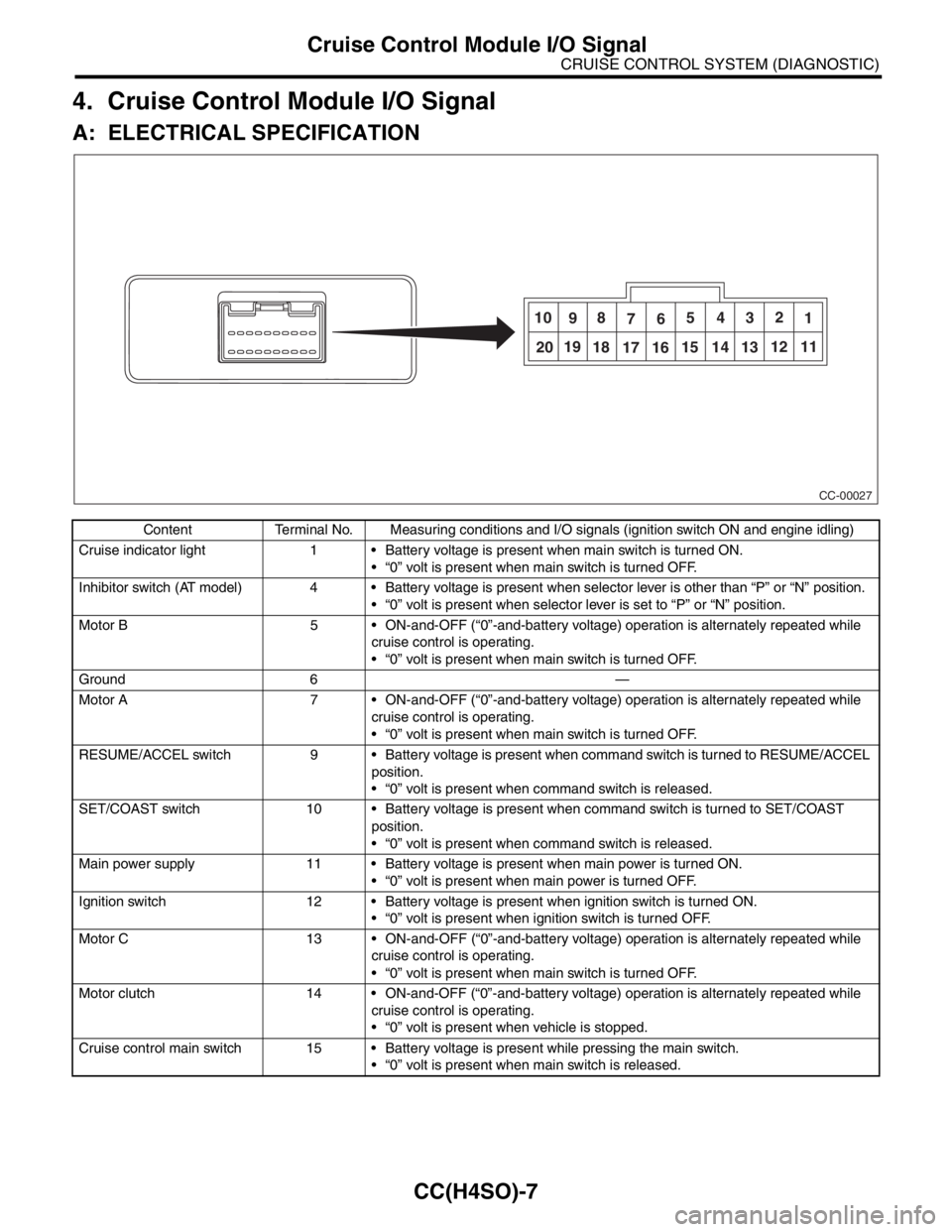
A: ELECTRICAL SPECIFICATION
Content Terminal No. Measuring conditions and I/O signals (ignition switch ON and engine idling)
Cruise indicator light 1 Battery voltage is present when main switch is turned ON.
“0” volt is present when main switch is turned OFF.
Inhibitor switch (AT model) 4 Battery voltage is present when selector lever is other than “P” or “N” position.
“0” volt is present when selector lever is set to “P” or “N” position.
Motor B 5 ON-and-OFF (“0”-and-battery voltage) operation is alternately repeated while
cruise control is operating.
“0” volt is present when main switch is turned OFF.
Ground 6 —
Motor A 7 ON-and-OFF (“0”-and-battery voltage) operation is alternately repeated while
cruise control is operating.
“0” volt is present when main switch is turned OFF.
RESUME/ACCEL switch 9 Battery voltage is present when command switch is turned to RESUME/ACCEL
position.
“0” volt is present when command switch is released.
SET/COAST switch 10 Battery voltage is present when command switch is turned to SET/COAST
position.
“0” volt is present when command switch is released.
Main power supply 11 Battery voltage is present when main power is turned ON.
“0” volt is present when main power is turned OFF.
Ignition switch 12 Battery voltage is present when ignition switch is turned ON.
“0” volt is present when ignition switch is turned OFF.
Motor C 13 ON-and-OFF (“0”-and-battery voltage) operation is alternately repeated while
cruise control is operating.
“0” volt is present when main switch is turned OFF.
Motor clutch 14 ON-and-OFF (“0”-and-battery voltage) operation is alternately repeated while
cruise control is operating.
“0” volt is present when vehicle is stopped.
Cruise control main switch 15 Battery voltage is present while pressing the main switch.
“0” volt is present when main switch is released.
CC-00027
10
98
765432
1
2019
18
17 1615 14 1312 11
Page 576 of 2870

CC(H4SO)-8
CRUISE CONTROL SYSTEM (DIAGNOSTIC)
Cruise Control Module I/O Signal
B: WIRING DIAGRAM
Brake switch/Clutch switch
(MT model)16 Leave clutch pedal released (MT model), while cruise control main switch is
turned ON.
Then check that;
Battery voltage is present when brake pedal is released.
“0” volt is present when brake pedal is depressed.
Additionally only in MT model, keep the cruise control main switch to ON and
leave brake pedal released.
Then check that;
Battery voltage is present when clutch pedal is released.
“0” volt is present when clutch pedal is depressed.
Data link connector 17 —
Data link connector 18 —
Vehicle speed sensor (MT
model)
TCM (AT model)19 Lift-up the vehicle until all four wheels are raised off ground, and then rotate any
wheel manually.
Approx. “5” and “0” volt pulse signals are alternately input to cruise control mod-
ule.
Stop light switch 20 Turn ignition switch to OFF.
Then check that;
Battery voltage is present when brake pedal is depressed.
“0” volt is present when brake pedal is released.
NOTE:
Voltage at terminals 5, 7, 13 and 14 cannot be checked unless vehicle is driving by cruise control operation.Content Terminal No. Measuring conditions and I/O signals (ignition switch ON and engine idling)