2004 SUBARU FORESTER engine
[x] Cancel search: enginePage 41 of 2870

AC-39
HVAC SYSTEM (HEATER, VENTILATOR AND A/C)
Heater Cooling Unit
14.Heater Cooling Unit
A: REMOVAL
1) Disconnect the ground cable from battery.
2) Using the refrigerant recovery system, dis-
charge refrigerant.
3) Drain the engine coolant from radiator.
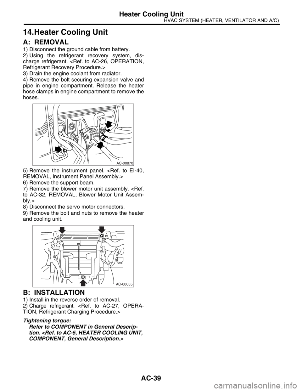
4) Remove the bolt securing expansion valve and
pipe in engine compartment. Release the heater
hose clamps in engine compartment to remove the
hoses.
5) Remove the instrument panel.
6) Remove the support beam.
7) Remove the blower motor unit assembly.
bly.>
8) Disconnect the servo motor connectors.
9) Remove the bolt and nuts to remove the heater
and cooling unit.
B: INSTALLATION
1) Install in the reverse order of removal.
2) Charge refrigerant.
Tightening torque:
Refer to COMPONENT in General Descrip-
tion.
AC-00870
AC-00055
Page 51 of 2870

AC-49
HVAC SYSTEM (HEATER, VENTILATOR AND A/C)
Heater Cock Solenoid Valve
24.Heater Cock Solenoid Valve
A: REMOVAL
1) Drain the engine coolant.
2) Remove the battery.
3) Remove the two bolts and disconnect harness
connector, and move the washer tank forward.
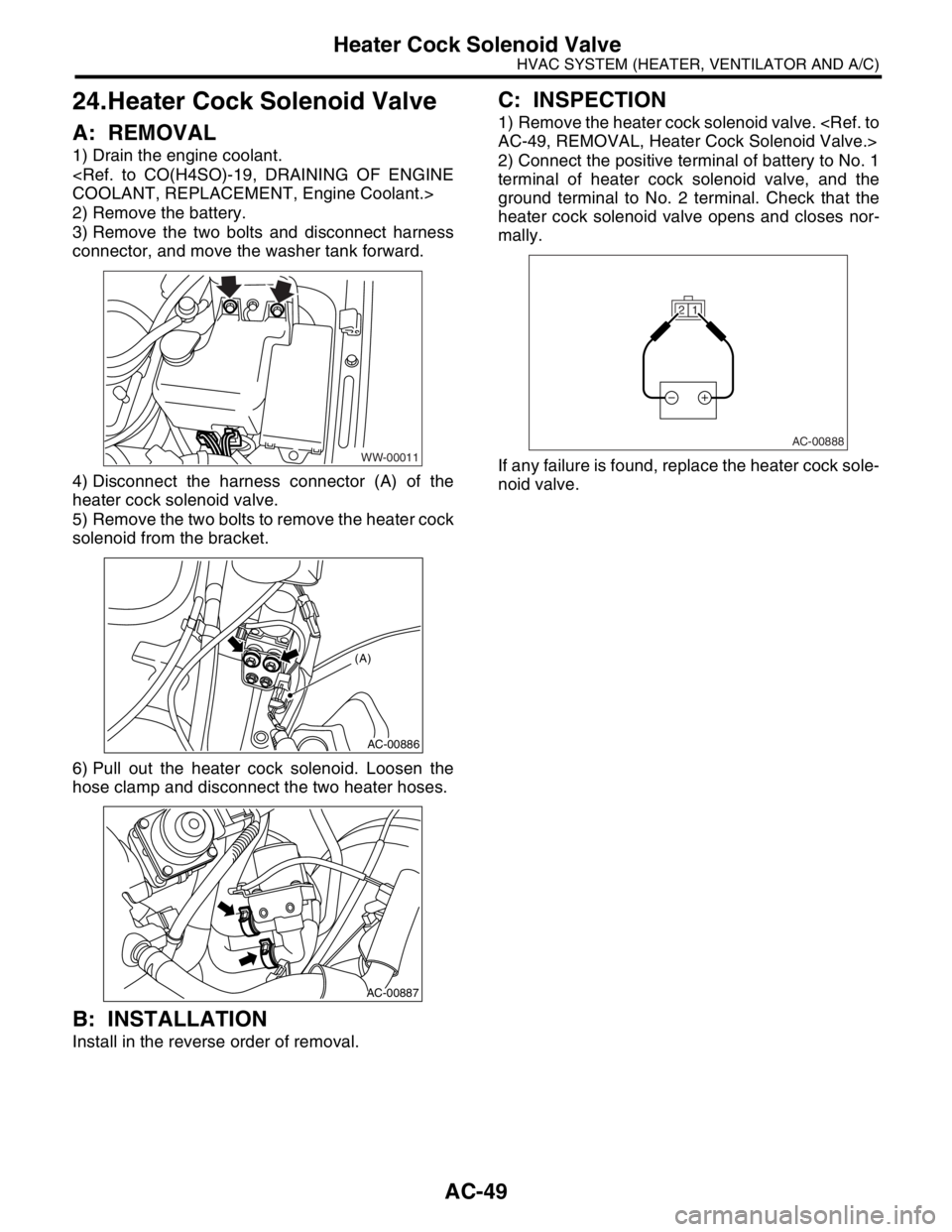
4) Disconnect the harness connector (A) of the
heater cock solenoid valve.
5) Remove the two bolts to remove the heater cock
solenoid from the bracket.
6) Pull out the heater cock solenoid. Loosen the
hose clamp and disconnect the two heater hoses.
B: INSTALLATION
Install in the reverse order of removal.
C: INSPECTION
1) Remove the heater cock solenoid valve.
2) Connect the positive terminal of battery to No. 1
terminal of heater cock solenoid valve, and the
ground terminal to No. 2 terminal. Check that the
heater cock solenoid valve opens and closes nor-
mally.
If any failure is found, replace the heater cock sole-
noid valve.
WW-00011
AC-00886
(A)
AC-00887
1 2
AC-00888
Page 52 of 2870

AC-50
HVAC SYSTEM (HEATER, VENTILATOR AND A/C)
General Diagnostics
25.General Diagnostics
A: INSPECTION
Symptom Repair order
Blower motorDoes not run.Fuse
Blower motor relay
Wiring harness
Blower motor
Blower motor resistor (Manual A/C model)
Blower switch
Noise Blower motor
CompressorDoes not run.Refrigerant
Fuse
A/C relay
Wiring harness
Magnet clutch
Compressor
Pressure switch
A/C switch
Blower switch
NoiseV- B e l t
Magnet clutch
Compressor
Condenser fanDoes not run.Fuse
Sub fan relay
Wiring harness
Noise Condenser fan motor
Cold air not emitted.Refrigerant
V- B e l t
Magnet clutch
Compressor
Pressure switch
Blower fan relay, Blower motor
A/C switch
Blower switch
Wiring harness
Heater duct
Heater vent duct
Control unit
Expansion valve
Evaporator
Air mix actuator (Auto A/C), Temperature control cable (Manual
A/C)
Warm air not emitted.Engine coolant
Aspirator hose
Blower switch
Air mix actuator (Auto A/C), Temperature control cable (Manual
A/C)
Heater core
Heater cock solenoid valve (Non-turbo model for EC/EK)
Page 59 of 2870

AC-3
HVAC SYSTEM (AUTO A/C)(DIAGNOSTIC)
General Description
2. General Description
A: CAUTION
1) Never connect the battery in reverse polarity.
Auto A/C control module may be destroyed instant-
ly.
2) Do not disconnect the battery terminals while the
engine is running.
A large counter electromotive force will be generat-
ed in the generator, and this voltage may damage
electronic parts such as auto A/C control module,
etc.
3) Before disconnecting the connectors of each
sensor and the auto A/C control module, be sure to
turn off the ignition switch.
Auto A/C control module may be damaged.
4) Every A/C-related part is a precision part. Do not
drop them.
5) Airbag system wiring harness is routed near the
A/C control panel (auto A/C control module) and
junction box.
CAUTION:
For airbag system, yellow-colored wiring har-
ness and connectors are all used. Do not use
the electrical test equipment on these circuits.
Be careful not to damage the airbag system
wiring harness when servicing the A/C control
panel (auto A/C control module) and junction
box.
B: INSPECTION
Before performing the diagnosis, check the follow-
ing items which might affect A/C system problems.
1. BATTERY
1) Measure battery voltage and specific gravity of
electrolyte.
Standard voltage: 12 V
Specific gravity: More than 1.260
2) Check the condition of the fuses for A/C system
power supply and other fuses.
3) Check the condition of harness and harness
connector connections.
2. ASPIRATOR HOSE
1) Turn the ignition switch to ON, and press the A/
C switch.
2) Turn the temperature control dial at maximum
hot position.
3) Press the defroster switch.
4) Turn the fan speed control dial to 4th position.5) Approach a strip of paper (b) in front of the in-ve-
hicle sensor suction port (a) located in the instru-
ment lower cover, and check that air is being
sucked into the port by seeing the paper moving to-
wards port.
NOTE:
Be careful not to let the paper get sucked into port.
6) If the paper does not move at all, remove the in-
strument panel lower cover
for improper connection of the aspirator hose (a),
in-vehicle sensor and heater unit, and repair them if
necessary.
3. A/C LINE
Check the connection for A/C line (A) and lower
side high-pressure pipe.
4. CONTROL LINKAGE
1) Check the state of mode door linkage.
2) Check the state of air mix door linkage.
3) Check the state of intake door linkage.
AC-00094
(a)
(a)
(b)
AC-00065
(a)
AC-00096
(A)
Page 60 of 2870

AC-4
HVAC SYSTEM (AUTO A/C)(DIAGNOSTIC)
General Description
5. CONTROL SWITCHES
Start and warm-up the engine completely.
1) Inspection using switches
2) Compressor operation inspection
3) Inspection of illumination control
No. Point to check Switch operation Judgment standard
1 Fan speed control dial Turn the fan speed control dial clockwise.Fan speed changes 1st → 2nd → 3rd → 4th
as dial turn.
2AUTO switch1) Press the AUTO switch.
2) Turn the temperature control dial to the left
fully, and set maximum cool position. Outlet air temperature: COOL
Fan speed: 4th
Outlet opening: VENT
Inlet opening: RECIRC
Compressor: AUTO
3) Turn the temperature control dial to the right
slowly, and change the setting from maximum
cool position to maximum hot position gradually. Outlet air temperature: COOL → HOT
Fan speed: AUTO
Outlet opening: AUTO
Inlet opening: AUTO
Compressor: AUTO
4) Turn the temperature control dial to the right
fully, and set maximum hot position. Outlet air temperature: HOT
Fan speed: 4th
Outlet opening: HEAT
Inlet opening: FRESH
Compressor: AUTO
3 Defroster switch Press the defroster switch. Outlet air temperature: AUTO
Fan speed: AUTO
Outlet opening: DEF
Inlet opening: FRESH
Compressor: ON
4FRESH/RECIRC
switchPress the FRESH/RECIRC switch.Inlet opening switches RECIRC → FRESH or
FRESH → RECIRC each time pressing the
switch.
5 Mode control dial Press the mode control dial.Outlet opening switches VENT → BI-LEVEL
→ HEAT → DEF/HEAT each time dialing
clockwise.
No. Point to check Switch operation Judgment standard
1 Compressor1) A/C switch is turned to ON.
2) Turn the fan speed control clockwise.Compressor: ON
No. Point to check Switch operation Judgment standard
1 Illumination1) Turn the lighting switch to ON. Illumination comes on.
2) Press the OFF switch one second or more. Illumination dimming is cancelled.
Page 61 of 2870

AC-5
HVAC SYSTEM (AUTO A/C)(DIAGNOSTIC)
Electrical Component Location
3. Electrical Component Location
A: LOCATION
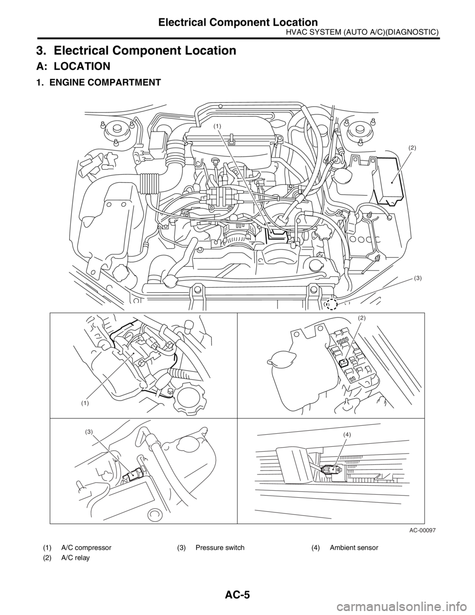
1. ENGINE COMPARTMENT
(1) A/C compressor (3) Pressure switch (4) Ambient sensor
(2) A/C relay
AC-00097 (1)
(2)
(4)
(1)
(3)
(2)
(3)
Page 63 of 2870

AC-7
HVAC SYSTEM (AUTO A/C)(DIAGNOSTIC)
Auto A/C Control Module I/O Signal
4. Auto A/C Control Module I/O Signal
A: ELECTRICAL SPECIFICATION
Terminal No. Content Measuring conditionSpecified
value
B9
Mode door actuator power supplyChanges outlet from VENT to DEF.
*2
B8 Changes outlet from DEF to VENT.
B7
Air mix door actuator power supplyChanges air mix door from COOL to HOT.
*1
B6 Changes air mix door from HOT to COOL.
B5 IGN power supply Ignition switch: ON Battery voltage
B4 Battery power supply Ignition switch: OFF, ACC, ON Battery voltage
B3 Sunload sensorIgnition switch: ON and under normal sunload
(without sunload: 5 V)3 V
B2 Evaporator sensor Ignition switch: ON 5 V or less
B1 Air mix door actuator P.B.R. signalAir mix door: COOL position 0.5 V
Air mix door: HOT position 4.5 V
B20
Intake door actuator signalAir inlet: FRESH (other positions: 12 V) 0 V
B19 Air inlet: MIX (other positions: 12 V) 0 V
B18 Air inlet: RECIRC (other positions: 12 V) 0 V
B17 A/C ON signal A/C: ON (A/C OFF: 0 V) 8 — 10 V
B16 Blower motor control *3 *3
B15 Blower fan ON signalWhen blower fan running (when blower fan not
running: 12 V)0 V
B13 Engine coolant temperature sensor When the engine coolant is at 49°C (120°F) 8.9 V
B12 In-vehicle sensor — —
B11 Ground When there is continuity to chassis ground 0 Ω
A7 Air mix door actuator P.B.R. reference voltage Ignition switch: ON 5 V
A5 Mode door actuator position detection signal OutletBI-LEVEL, DEF 5 V
VENT, HEAT, DEF/HEAT 0 V
A4 Mode door actuator position detection signal OutletHEAT, DEF/HEAT, DEF 5 V
VENT, BI-LEVEL 0 V
A1 Illumination power supplyIgnition switch: ON, light switch: ON Battery voltage
Ignition switch: ON, light switch: OFF 0 V
A16 Sensor ground When there is continuity to chassis ground 0 Ω
AC-00099
1 2 3 4 5 6 7 8 910
11 12 13 14 15 16 17 18 19 201 2 3 4 5 6 7 8
9
10 11 12 13 14 15 16
i48B: To A:To
i49
Page 66 of 2870

AC-10
HVAC SYSTEM (AUTO A/C)(DIAGNOSTIC)
Diagnostic Chart for Self-Diagnosis
Step Check Yes No
1 SELECT CONTROL PANEL TO SELF-DIAG-
NOSIS MODE.
1) Turn the ignition switch to OFF.
2) Start the engine while pressing defroster
switch and A/C switch.
N
OTE:
Self-diagnosis can also be performed with the
ignition switch ON, but start the engine be-
cause telling the magnet clutch operation is dif-
ficult.
3) The LED in A/C control panel blinks.Does the self-diagnosis mode
operate?Go to step 2.
NOSIS SYS-
TEMS DO NOT
OPERATE, Diag-
nostics for A/C
System Malfunc-
tion.>
2 CHECK LED ILLUMINATION.
Make sure that three LED blink in turn on A/C
control panel (5 patterns are repeated 2 times).Do all LED blink? Go to step 3.Go to step 5.
3 CHECK SENSORS MALFUNCTION.
1) After completing the LED check or when
AUTO switch is pressed, the A/C switch LED
illuminates, and then the sensor check is
started.
2) Check the input signal of each sensor in
turn. If there are any trouble for each sensor,
DEF, MODE and fan speed LEDs are blinked.
Also check for each sensor is possible respec-
tively every time AUTO switch is pressed. (At
this time, the AUTO switch LED illuminates.)
3) If there is no trouble, DEF, MODE and fan
speed LEDs are turned off.
N
OTE:
Rear window defogger LED illuminates in case
of stored malfunction but does not illuminate in
case of present malfunction.Does each DEF, MODE and
fan speed LED turn off?Go to step 4.Confirm the com-
bination of illumi-
nating LEDs by
using Sensor
Check Table, and
identify the mal-
functioning sensor
before repairing.
TABLE, OPERA-
TION, Diagnostic
Chart for Self-
Diagnosis.>
4 CHECK OPERATION OF EACH ACTUATOR,
COMPRESSOR AND FAN MOTOR.
1) Press the FRESH/RECIRC switch
(FRESH/RECIRC switch LED illuminates at
this time.).
2) Refer to OPERATING MODE TABLE to
check the operation of each actuator, compres-
sor and fan motor.
Chart for Self-Diagnosis.>
Also check for each step is possible respec-
tively every time AUTO switch pressed. (At this
time, the AUTO switch LED illuminates.)Does each actuator, compres-
sor and fan motor operate
according to operating mode
table?Press the OFF
switch or turn the
ignition switch to
OFF and finish the
self-diagnosis
mode.Refer to each
diagnostics chart
for actuator, com-
pressor and fan
motor, and repair
the malfunctioning
par t as necessary.
C System Mal-
function.>
Procedure for
Actuators.>
5 CHECK POOR CONTACT.
Check the auto A/C control module connector
for poor contact.Is there a poor contact in con-
nector?Replace the auto
A/C control mod-
ule.Repair the con-
nector.