Page 1051 of 2870
LU(H4SO)-23
LUBRICATION
Engine Oil Filter
8. Engine Oil Filter
A: REMOVAL
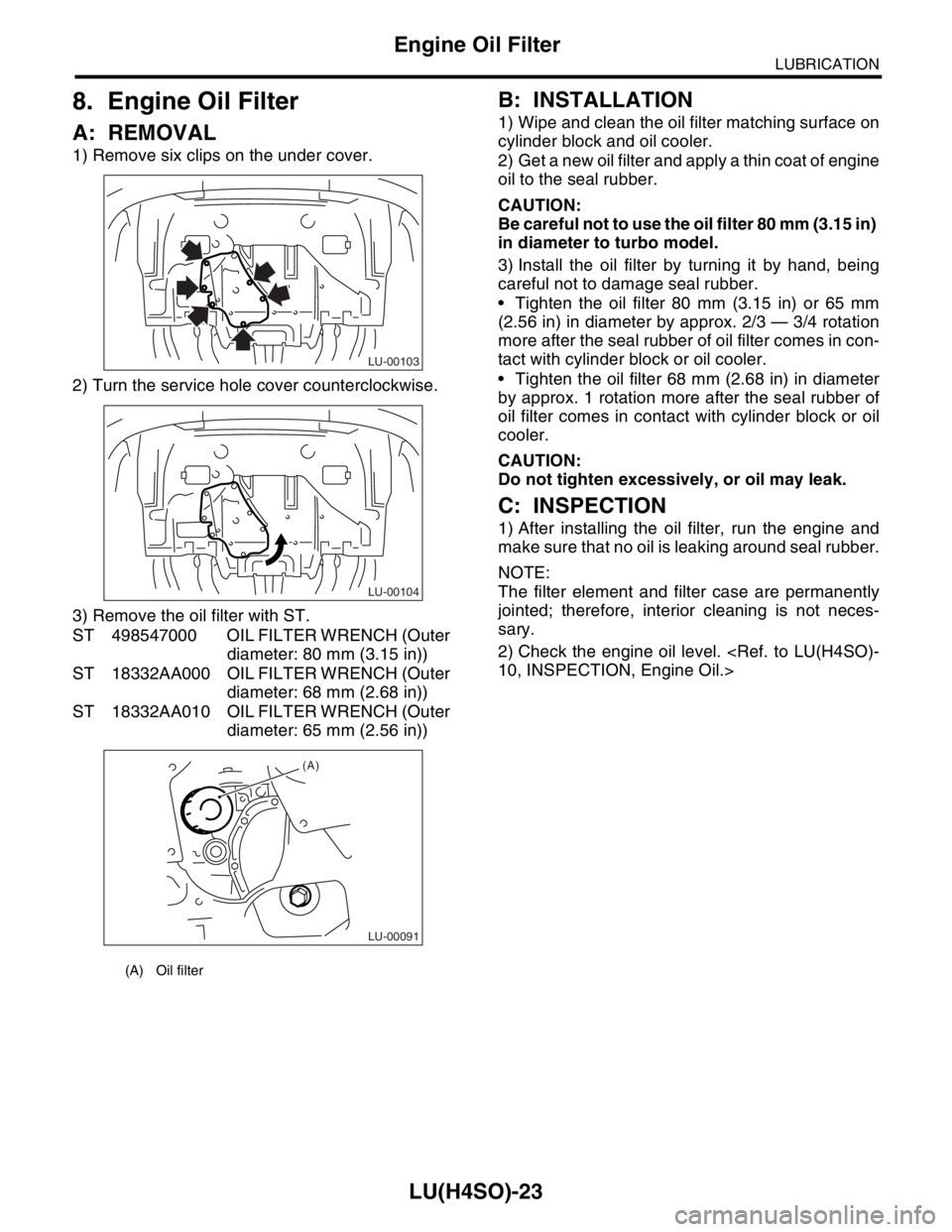
1) Remove six clips on the under cover.
2) Turn the service hole cover counterclockwise.
3) Remove the oil filter with ST.
ST 498547000 OIL FILTER WRENCH (Outer
diameter: 80 mm (3.15 in))
ST 18332AA000 OIL FILTER WRENCH (Outer
diameter: 68 mm (2.68 in))
ST 18332AA010 OIL FILTER WRENCH (Outer
diameter: 65 mm (2.56 in))
B: INSTALLATION
1) Wipe and clean the oil filter matching surface on
cylinder block and oil cooler.
2) Get a new oil filter and apply a thin coat of engine
oil to the seal rubber.
CAUTION:
Be careful not to use the oil filter 80 mm (3.15 in)
in diameter to turbo model.
3) Install the oil filter by turning it by hand, being
careful not to damage seal rubber.
Tighten the oil filter 80 mm (3.15 in) or 65 mm
(2.56 in) in diameter by approx. 2/3 — 3/4 rotation
more after the seal rubber of oil filter comes in con-
tact with cylinder block or oil cooler.
Tighten the oil filter 68 mm (2.68 in) in diameter
by approx. 1 rotation more after the seal rubber of
oil filter comes in contact with cylinder block or oil
cooler.
CAUTION:
Do not tighten excessively, or oil may leak.
C: INSPECTION
1) After installing the oil filter, run the engine and
make sure that no oil is leaking around seal rubber.
NOTE:
The filter element and filter case are permanently
jointed; therefore, interior cleaning is not neces-
sary.
2) Check the engine oil level.
10, INSPECTION, Engine Oil.>
(A) Oil filter
LU-00103
LU-00104
LU-00091
(A)
Page 1053 of 2870
FUJI HEAVY INDUSTRIES LTD. G8080GE2
2004 FORESTER SERVICE MANUAL QUICK REFERENCE INDEX
ENGINE SECTION 1
This service manual has been prepared
to provide SUBARU service personnel
with the necessary information and data
for the correct maintenance and repair
of SUBARU vehicles.
This manual includes the procedures
for maintenance, disassembling, reas-
sembling, inspection and adjustment of
components and diagnostics for guid-
ance of experienced mechanics.
Please peruse and utilize this manual
fully to ensure complete repair work for
satisfying our customers by keeping
their vehicle in optimum condition.
When replacement of parts during
repair work is needed, be sure to use
SUBARU genuine parts.
All information, illustration and specifi-
cations contained in this manual are
based on the latest product information
available at the time of publication
approval.FUEL INJECTION (FUEL SYSTEM) FU(H4SO)
EMISSION CONTROL
(AUX. EMISSION CONTROL DEVICE)EC(H4SO)
INTAKE (INDUCTION) IN(H4SO)
MECHANICAL ME(H4SO)
EXHAUST EX(H4SO)
COOLING CO(H4SO)
LUBRICATION LU(H4SO)
SPEED CONTROL SYSTEM SP(H4SO)
IGNITION IG(H4SO)
STARTING/CHARGING SYSTEM SC(H4SO)
ENGINE (DIAGNOSTIC) EN(H4SO)
Page 1060 of 2870
SP(H4SO)-7
SPEED CONTROL SYSTEM
Accelerator Pedal
E: INSPECTION
1. ACCELERATOR PEDAL
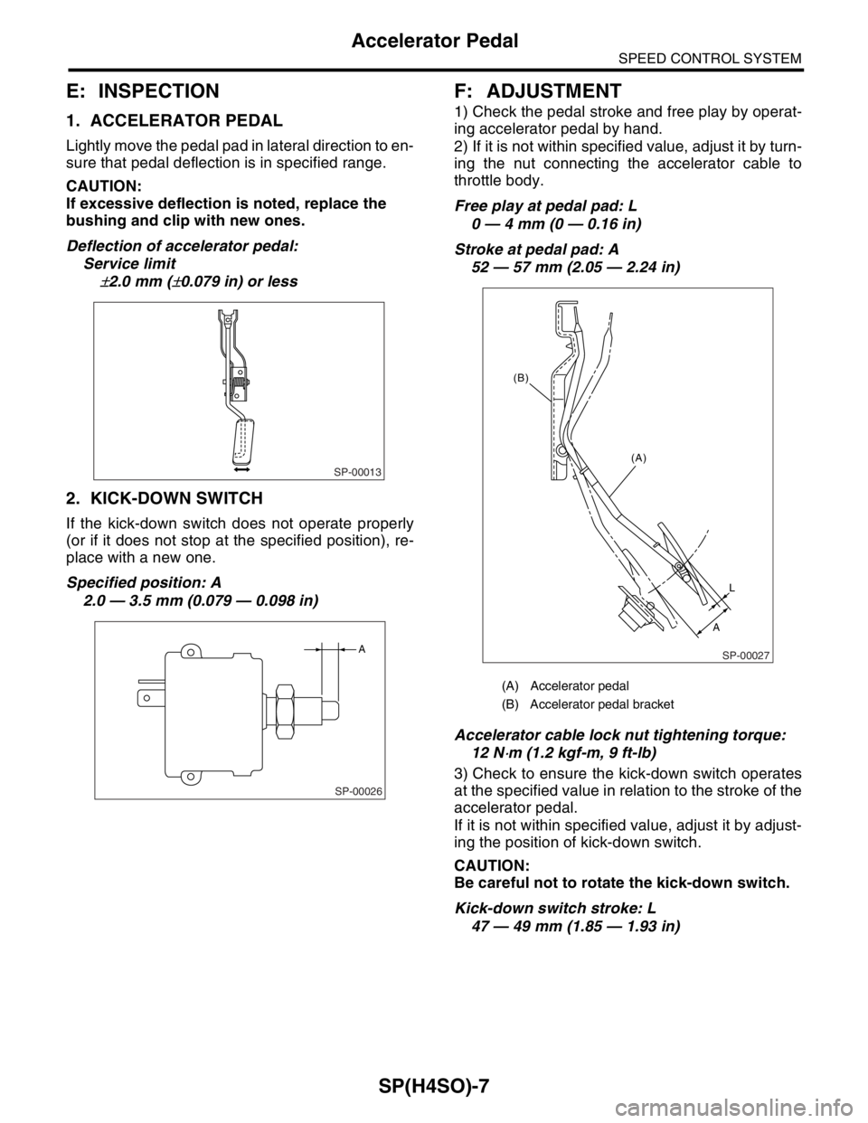
Lightly move the pedal pad in lateral direction to en-
sure that pedal deflection is in specified range.
CAUTION:
If excessive deflection is noted, replace the
bushing and clip with new ones.
Deflection of accelerator pedal:
Service limit
±2.0 mm (±0.079 in) or less
2. KICK-DOWN SWITCH
If the kick-down switch does not operate properly
(or if it does not stop at the specified position), re-
place with a new one.
Specified position: A
2.0 — 3.5 mm (0.079 — 0.098 in)
F: ADJUSTMENT
1) Check the pedal stroke and free play by operat-
ing accelerator pedal by hand.
2) If it is not within specified value, adjust it by turn-
ing the nut connecting the accelerator cable to
throttle body.
Free play at pedal pad: L
0 — 4 mm (0 — 0.16 in)
Stroke at pedal pad: A
52 — 57 mm (2.05 — 2.24 in)
Accelerator cable lock nut tightening torque:
12 N
⋅m (1.2 kgf-m, 9 ft-lb)
3) Check to ensure the kick-down switch operates
at the specified value in relation to the stroke of the
accelerator pedal.
If it is not within specified value, adjust it by adjust-
ing the position of kick-down switch.
CAUTION:
Be careful not to rotate the kick-down switch.
Kick-down switch stroke: L
47 — 49 mm (1.85 — 1.93 in)
SP-00013
SP-00026
A
(A) Accelerator pedal
(B) Accelerator pedal bracket
SP-00027
(A)
L
A (B)
Page 1064 of 2870
FUJI HEAVY INDUSTRIES LTD. G8080GE2
2004 FORESTER SERVICE MANUAL QUICK REFERENCE INDEX
ENGINE SECTION 1
This service manual has been prepared
to provide SUBARU service personnel
with the necessary information and data
for the correct maintenance and repair
of SUBARU vehicles.
This manual includes the procedures
for maintenance, disassembling, reas-
sembling, inspection and adjustment of
components and diagnostics for guid-
ance of experienced mechanics.
Please peruse and utilize this manual
fully to ensure complete repair work for
satisfying our customers by keeping
their vehicle in optimum condition.
When replacement of parts during
repair work is needed, be sure to use
SUBARU genuine parts.
All information, illustration and specifi-
cations contained in this manual are
based on the latest product information
available at the time of publication
approval.FUEL INJECTION (FUEL SYSTEM) FU(H4SO)
EMISSION CONTROL
(AUX. EMISSION CONTROL DEVICE)EC(H4SO)
INTAKE (INDUCTION) IN(H4SO)
MECHANICAL ME(H4SO)
EXHAUST EX(H4SO)
COOLING CO(H4SO)
LUBRICATION LU(H4SO)
SPEED CONTROL SYSTEM SP(H4SO)
IGNITION IG(H4SO)
STARTING/CHARGING SYSTEM SC(H4SO)
ENGINE (DIAGNOSTIC) EN(H4SO)
Page 1075 of 2870
FUJI HEAVY INDUSTRIES LTD. G8080GE2
2004 FORESTER SERVICE MANUAL QUICK REFERENCE INDEX
ENGINE SECTION 1
This service manual has been prepared
to provide SUBARU service personnel
with the necessary information and data
for the correct maintenance and repair
of SUBARU vehicles.
This manual includes the procedures
for maintenance, disassembling, reas-
sembling, inspection and adjustment of
components and diagnostics for guid-
ance of experienced mechanics.
Please peruse and utilize this manual
fully to ensure complete repair work for
satisfying our customers by keeping
their vehicle in optimum condition.
When replacement of parts during
repair work is needed, be sure to use
SUBARU genuine parts.
All information, illustration and specifi-
cations contained in this manual are
based on the latest product information
available at the time of publication
approval.FUEL INJECTION (FUEL SYSTEM) FU(H4SO)
EMISSION CONTROL
(AUX. EMISSION CONTROL DEVICE)EC(H4SO)
INTAKE (INDUCTION) IN(H4SO)
MECHANICAL ME(H4SO)
EXHAUST EX(H4SO)
COOLING CO(H4SO)
LUBRICATION LU(H4SO)
SPEED CONTROL SYSTEM SP(H4SO)
IGNITION IG(H4SO)
STARTING/CHARGING SYSTEM SC(H4SO)
ENGINE (DIAGNOSTIC) EN(H4SO)
Page 1086 of 2870
SC(H4SO)-11
STARTING/CHARGING SYSTEM
Starter
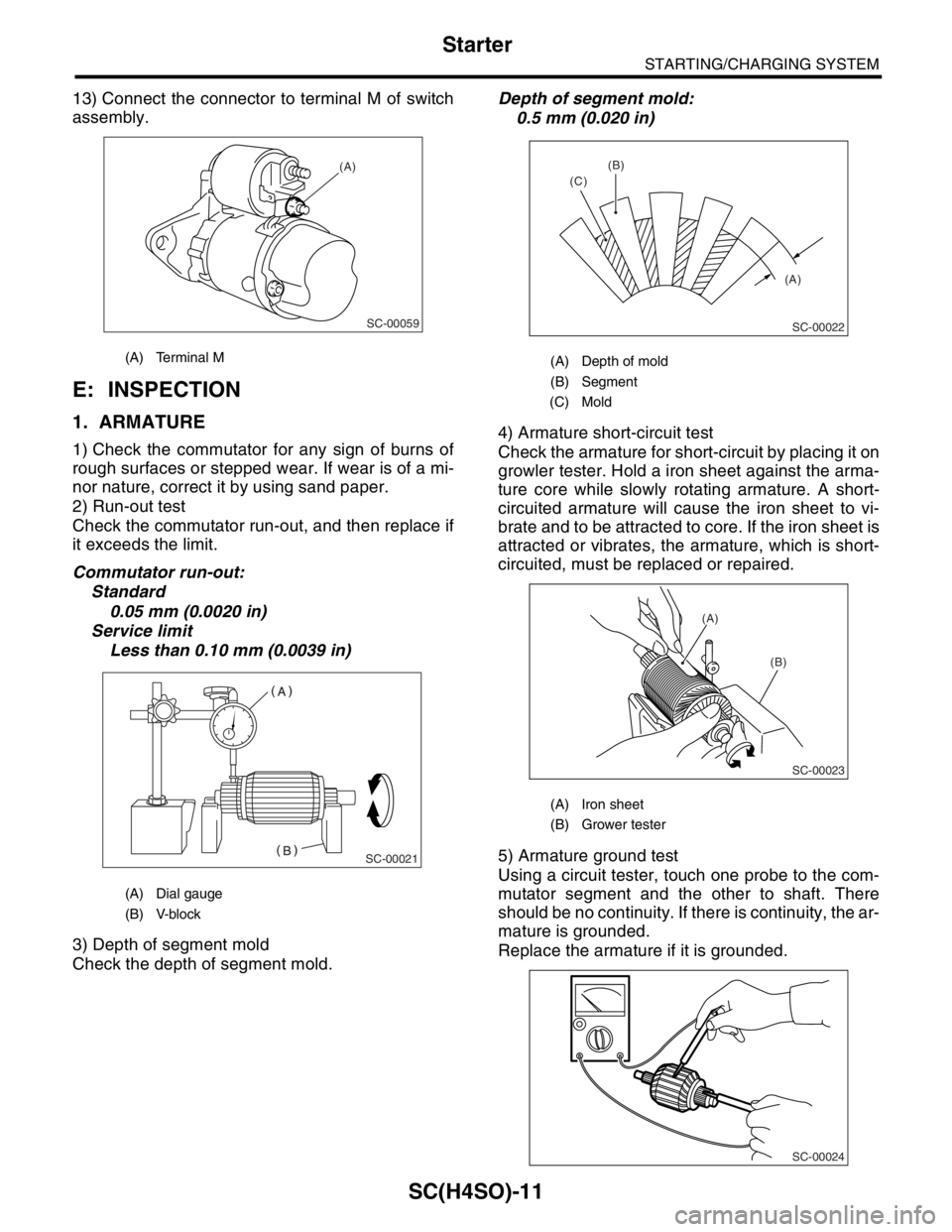
13) Connect the connector to terminal M of switch
assembly.
E: INSPECTION
1. ARMATURE
1) Check the commutator for any sign of burns of
rough surfaces or stepped wear. If wear is of a mi-
nor nature, correct it by using sand paper.
2) Run-out test
Check the commutator run-out, and then replace if
it exceeds the limit.
Commutator run-out:
Standard
0.05 mm (0.0020 in)
Service limit
Less than 0.10 mm (0.0039 in)
3) Depth of segment mold
Check the depth of segment mold.Depth of segment mold:
0.5 mm (0.020 in)
4) Armature short-circuit test
Check the armature for short-circuit by placing it on
growler tester. Hold a iron sheet against the arma-
ture core while slowly rotating armature. A short-
circuited armature will cause the iron sheet to vi-
brate and to be attracted to core. If the iron sheet is
attracted or vibrates, the armature, which is short-
circuited, must be replaced or repaired.
5) Armature ground test
Using a circuit tester, touch one probe to the com-
mutator segment and the other to shaft. There
should be no continuity. If there is continuity, the ar-
mature is grounded.
Replace the armature if it is grounded.
(A) Terminal M
(A) Dial gauge
(B) V-block
SC-00059
(A)
SC-00021
(A) Depth of mold
(B) Segment
(C) Mold
(A) Iron sheet
(B) Grower tester
(A) (B)
(C)
SC-00022
(A)
(B)
SC-00023
SC-00024
Page 1087 of 2870
SC(H4SO)-12
STARTING/CHARGING SYSTEM
Starter
2. YOKE
Make sure the pole is set in position.
3. OVERRUNNING CLUTCH
Inspect the teeth of pinion for wear and damage.
Replace if it is damaged. Rotate the pinion in direc-
tion of rotation (counterclockwise). It should rotate
smoothly. But in opposite direction, it should be
locked.
CAUTION:
Do not clean the overrunning clutch with oil to
prevent grease from flowing out.
4. BRUSH AND BRUSH HOLDER
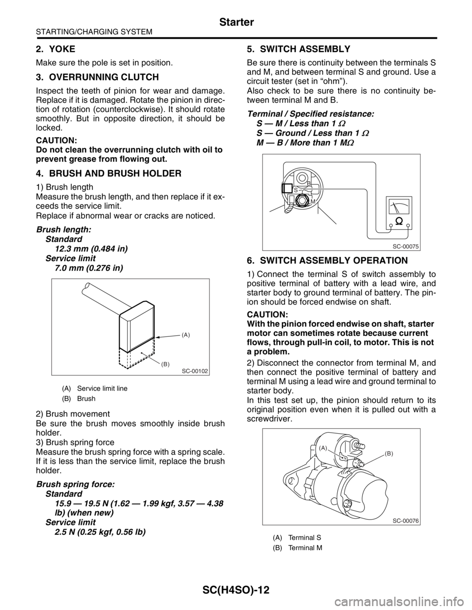
1) Brush length
Measure the brush length, and then replace if it ex-
ceeds the service limit.
Replace if abnormal wear or cracks are noticed.
Brush length:
Standard
12.3 mm (0.484 in)
Service limit
7.0 mm (0.276 in)
2) Brush movement
Be sure the brush moves smoothly inside brush
holder.
3) Brush spring force
Measure the brush spring force with a spring scale.
If it is less than the service limit, replace the brush
holder.
Brush spring force:
Standard
15.9 — 19.5 N (1.62 — 1.99 kgf, 3.57 — 4.38
lb) (when new)
Service limit
2.5 N (0.25 kgf, 0.56 lb)
5. SWITCH ASSEMBLY
Be sure there is continuity between the terminals S
and M, and between terminal S and ground. Use a
circuit tester (set in “ohm”).
Also check to be sure there is no continuity be-
tween terminal M and B.
Terminal / Specified resistance:
S — M / Less than 1
Ω
S — Ground / Less than 1 Ω
M — B / More than 1 MΩ
6. SWITCH ASSEMBLY OPERATION
1) Connect the terminal S of switch assembly to
positive terminal of battery with a lead wire, and
starter body to ground terminal of battery. The pin-
ion should be forced endwise on shaft.
CAUTION:
With the pinion forced endwise on shaft, starter
motor can sometimes rotate because current
flows, through pull-in coil, to motor. This is not
a problem.
2) Disconnect the connector from terminal M, and
then connect the positive terminal of battery and
terminal M using a lead wire and ground terminal to
starter body.
In this test set up, the pinion should return to its
original position even when it is pulled out with a
screwdriver.
(A) Service limit line
(B) Brush
SC-00102
(A)
(B)
(A) Terminal S
(B) Terminal M
SC-00075
B
M
S
SC-00076
(B) (A)
Page 1095 of 2870
SC(H4SO)-20
STARTING/CHARGING SYSTEM
Generator
3. STARTOR
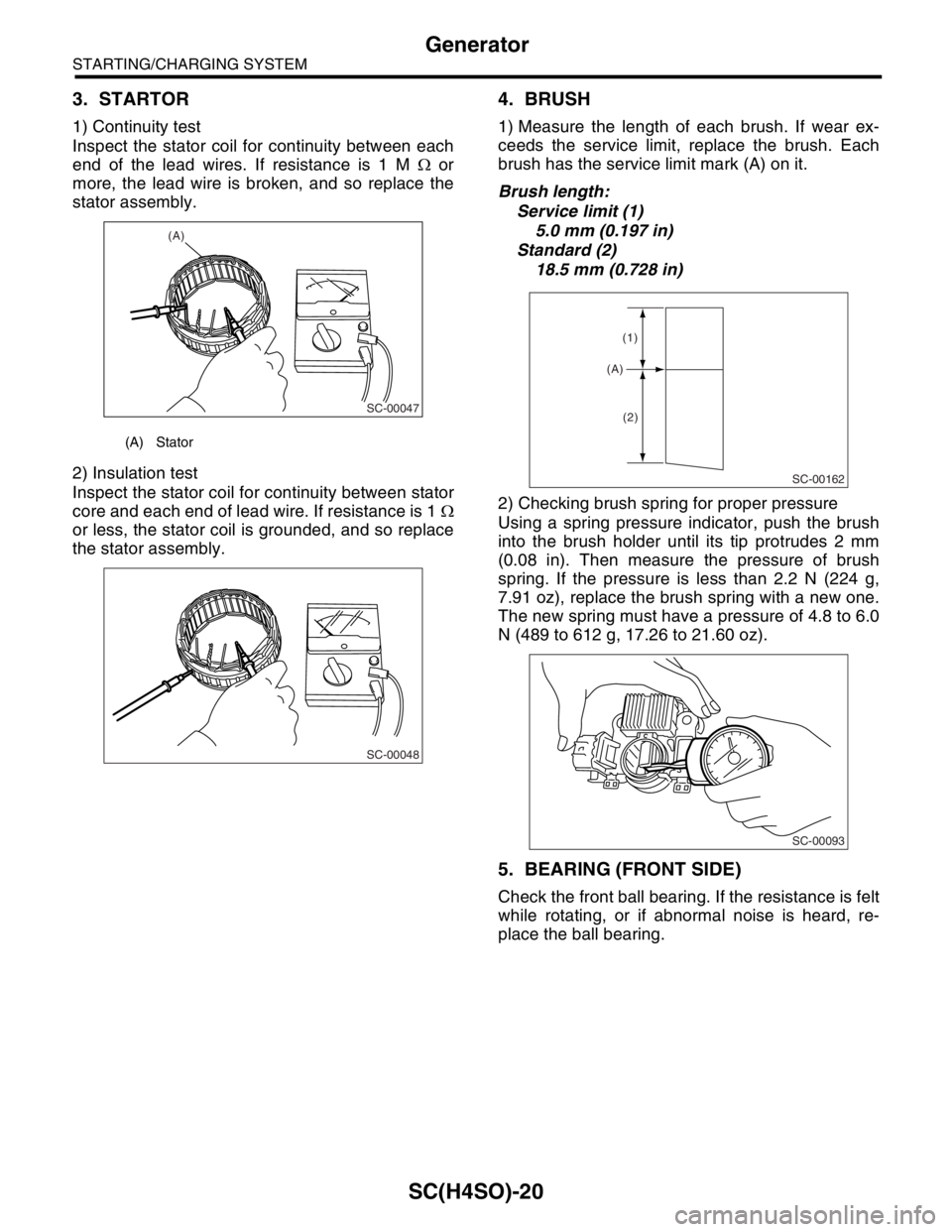
1) Continuity test
Inspect the stator coil for continuity between each
end of the lead wires. If resistance is 1 M Ω or
more, the lead wire is broken, and so replace the
stator assembly.
2) Insulation test
Inspect the stator coil for continuity between stator
core and each end of lead wire. If resistance is 1 Ω
or less, the stator coil is grounded, and so replace
the stator assembly.
4. BRUSH
1) Measure the length of each brush. If wear ex-
ceeds the service limit, replace the brush. Each
brush has the service limit mark (A) on it.
Brush length:
Service limit (1)
5.0 mm (0.197 in)
Standard (2)
18.5 mm (0.728 in)
2) Checking brush spring for proper pressure
Using a spring pressure indicator, push the brush
into the brush holder until its tip protrudes 2 mm
(0.08 in). Then measure the pressure of brush
spring. If the pressure is less than 2.2 N (224 g,
7.91 oz), replace the brush spring with a new one.
The new spring must have a pressure of 4.8 to 6.0
N (489 to 612 g, 17.26 to 21.60 oz).
5. BEARING (FRONT SIDE)
Check the front ball bearing. If the resistance is felt
while rotating, or if abnormal noise is heard, re-
place the ball bearing.
(A) Stator
(A)
SC-00047
SC-00048
SC-00162
(A)
(1)
(2)
SC-00093