Page 781 of 2870
PM-44
PERIODIC MAINTENANCE SERVICE
Steering System (Power Steering)
Page 782 of 2870
FUJI HEAVY INDUSTRIES LTD. G8080GE2
2004 FORESTER SERVICE MANUAL QUICK REFERENCE INDEX
ENGINE SECTION 1
This service manual has been prepared
to provide SUBARU service personnel
with the necessary information and data
for the correct maintenance and repair
of SUBARU vehicles.
This manual includes the procedures
for maintenance, disassembling, reas-
sembling, inspection and adjustment of
components and diagnostics for guid-
ance of experienced mechanics.
Please peruse and utilize this manual
fully to ensure complete repair work for
satisfying our customers by keeping
their vehicle in optimum condition.
When replacement of parts during
repair work is needed, be sure to use
SUBARU genuine parts.
All information, illustration and specifi-
cations contained in this manual are
based on the latest product information
available at the time of publication
approval.FUEL INJECTION (FUEL SYSTEM) FU(H4SO)
EMISSION CONTROL
(AUX. EMISSION CONTROL DEVICE)EC(H4SO)
INTAKE (INDUCTION) IN(H4SO)
MECHANICAL ME(H4SO)
EXHAUST EX(H4SO)
COOLING CO(H4SO)
LUBRICATION LU(H4SO)
SPEED CONTROL SYSTEM SP(H4SO)
IGNITION IG(H4SO)
STARTING/CHARGING SYSTEM SC(H4SO)
ENGINE (DIAGNOSTIC) EN(H4SO)
Page 831 of 2870
FU(H4SO)-49
FUEL INJECTION (FUEL SYSTEM)
Fuel Tank
B: INSTALLATION
1) Support the fuel tank with transmission jack and
push the fuel tank harness into access hole with
grommet.
2) Set the fuel tank and temporarily tighten the
bolts of fuel tank bands.
WARNING:
A helper is required to perform this work.
3) Connect the two-way valve hose (A) to two-way
valve and connect the canister hose (B) to canister.
4) Connect the fuel filler hose and air vent hose.5) Connect the fuel hoses, and secure them with
clips and quick connector.
INSTALLATION, Fuel Delivery, Return and Evapo-
ration Lines.>
6) Tighten the band mounting bolts.
Tightening torque:
33 N
⋅m (3.4 kgf-m, 24.3 ft-lb)
7) Install the rear crossmember.
INSTALLATION, Rear Crossmember.>
8) Connect the connector (A) to fuel tank cord and
plug the service hole with grommet (B).
9) Set the rear seat and floor mat.
FU-00411
(A)(B)
FU-00091
FU-00092
FU-00093
FU-00411
(B)
(A)
FU-00090
Page 840 of 2870
FU(H4SO)-58
FUEL INJECTION (FUEL SYSTEM)
Fuel Sub Level Sensor
24.Fuel Sub Level Sensor
A: REMOVAL
WARNING:
Place “NO FIRE” signs near the working area.
Be careful not to spill fuel.
1) Disconnect the ground cable from battery.
2) Lift-up the vehicle.
3) Drain fuel from the fuel tank. Set a container un-
der the vehicle and remove the drain plug from fuel
tank.
4) Tighten the fuel drain plug.
Tightening torque:
26 N
⋅m (2.7 kgf-m, 19.2 ft-lb)
5) Remove the rear seat.6) Remove the service hole cover.
7) Disconnect the connector from fuel sub level
sensor.
8) Disconnect the fuel jet pump hose.
9) Remove the bolts which install fuel sub level
sensor on fuel tank.
10) Remove the fuel sub level sensor.
FU-00009
FU-00089
FU-00089
FU-00113
FU-00114
FU-00115
FU-00116
Page 849 of 2870
FUJI HEAVY INDUSTRIES LTD. G8080GE2
2004 FORESTER SERVICE MANUAL QUICK REFERENCE INDEX
ENGINE SECTION 1
This service manual has been prepared
to provide SUBARU service personnel
with the necessary information and data
for the correct maintenance and repair
of SUBARU vehicles.
This manual includes the procedures
for maintenance, disassembling, reas-
sembling, inspection and adjustment of
components and diagnostics for guid-
ance of experienced mechanics.
Please peruse and utilize this manual
fully to ensure complete repair work for
satisfying our customers by keeping
their vehicle in optimum condition.
When replacement of parts during
repair work is needed, be sure to use
SUBARU genuine parts.
All information, illustration and specifi-
cations contained in this manual are
based on the latest product information
available at the time of publication
approval.FUEL INJECTION (FUEL SYSTEM) FU(H4SO)
EMISSION CONTROL
(AUX. EMISSION CONTROL DEVICE)EC(H4SO)
INTAKE (INDUCTION) IN(H4SO)
MECHANICAL ME(H4SO)
EXHAUST EX(H4SO)
COOLING CO(H4SO)
LUBRICATION LU(H4SO)
SPEED CONTROL SYSTEM SP(H4SO)
IGNITION IG(H4SO)
STARTING/CHARGING SYSTEM SC(H4SO)
ENGINE (DIAGNOSTIC) EN(H4SO)
Page 860 of 2870
FUJI HEAVY INDUSTRIES LTD. G8080GE2
2004 FORESTER SERVICE MANUAL QUICK REFERENCE INDEX
ENGINE SECTION 1
This service manual has been prepared
to provide SUBARU service personnel
with the necessary information and data
for the correct maintenance and repair
of SUBARU vehicles.
This manual includes the procedures
for maintenance, disassembling, reas-
sembling, inspection and adjustment of
components and diagnostics for guid-
ance of experienced mechanics.
Please peruse and utilize this manual
fully to ensure complete repair work for
satisfying our customers by keeping
their vehicle in optimum condition.
When replacement of parts during
repair work is needed, be sure to use
SUBARU genuine parts.
All information, illustration and specifi-
cations contained in this manual are
based on the latest product information
available at the time of publication
approval.FUEL INJECTION (FUEL SYSTEM) FU(H4SO)
EMISSION CONTROL
(AUX. EMISSION CONTROL DEVICE)EC(H4SO)
INTAKE (INDUCTION) IN(H4SO)
MECHANICAL ME(H4SO)
EXHAUST EX(H4SO)
COOLING CO(H4SO)
LUBRICATION LU(H4SO)
SPEED CONTROL SYSTEM SP(H4SO)
IGNITION IG(H4SO)
STARTING/CHARGING SYSTEM SC(H4SO)
ENGINE (DIAGNOSTIC) EN(H4SO)
Page 869 of 2870
FUJI HEAVY INDUSTRIES LTD. G8080GE2
2004 FORESTER SERVICE MANUAL QUICK REFERENCE INDEX
ENGINE SECTION 1
This service manual has been prepared
to provide SUBARU service personnel
with the necessary information and data
for the correct maintenance and repair
of SUBARU vehicles.
This manual includes the procedures
for maintenance, disassembling, reas-
sembling, inspection and adjustment of
components and diagnostics for guid-
ance of experienced mechanics.
Please peruse and utilize this manual
fully to ensure complete repair work for
satisfying our customers by keeping
their vehicle in optimum condition.
When replacement of parts during
repair work is needed, be sure to use
SUBARU genuine parts.
All information, illustration and specifi-
cations contained in this manual are
based on the latest product information
available at the time of publication
approval.FUEL INJECTION (FUEL SYSTEM) FU(H4SO)
EMISSION CONTROL
(AUX. EMISSION CONTROL DEVICE)EC(H4SO)
INTAKE (INDUCTION) IN(H4SO)
MECHANICAL ME(H4SO)
EXHAUST EX(H4SO)
COOLING CO(H4SO)
LUBRICATION LU(H4SO)
SPEED CONTROL SYSTEM SP(H4SO)
IGNITION IG(H4SO)
STARTING/CHARGING SYSTEM SC(H4SO)
ENGINE (DIAGNOSTIC) EN(H4SO)
Page 879 of 2870
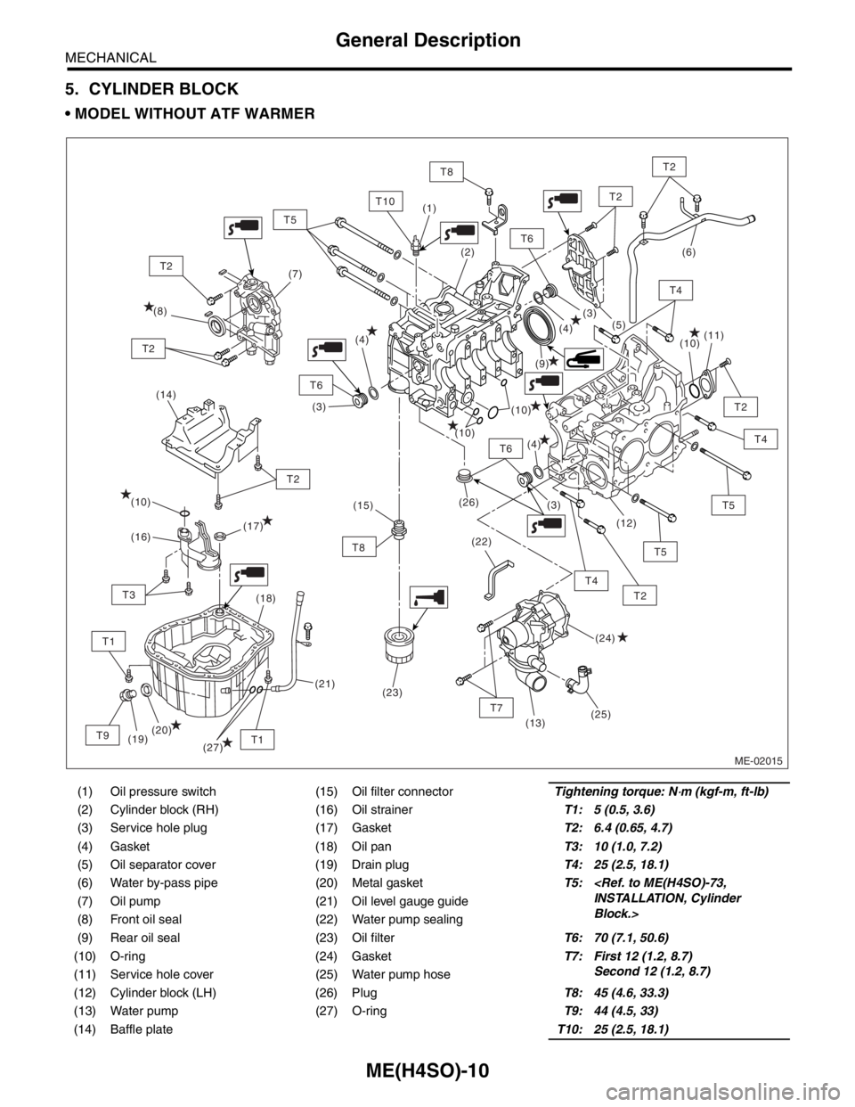
ME(H4SO)-10
MECHANICAL
General Description
5. CYLINDER BLOCK
MODEL WITHOUT ATF WARMER
(1) Oil pressure switch (15) Oil filter connectorTightening torque: N⋅m (kgf-m, ft-lb)
(2) Cylinder block (RH) (16) Oil strainerT1: 5 (0.5, 3.6)
(3) Service hole plug (17) GasketT2: 6.4 (0.65, 4.7)
(4) Gasket (18) Oil panT3: 10 (1.0, 7.2)
(5) Oil separator cover (19) Drain plugT4: 25 (2.5, 18.1)
(6) Water by-pass pipe (20) Metal gasketT5:
INSTALLATION, Cylinder
Block.> (7) Oil pump (21) Oil level gauge guide
(8) Front oil seal (22) Water pump sealing
(9) Rear oil seal (23) Oil filterT6: 70 (7.1, 50.6)
(10) O-ring (24) GasketT7: First 12 (1.2, 8.7)
Second 12 (1.2, 8.7)
(11) Service hole cover (25) Water pump hose
(12) Cylinder block (LH) (26) PlugT8: 45 (4.6, 33.3)
(13) Water pump (27) O-ringT9: 44 (4.5, 33)
(14) Baffle plateT10: 25 (2.5, 18.1)
ME-02015
(14)
T6
T7
T2
T2
T4
T8
T4
T5
T2
T6
T6
T10
T1
T2
T8
T1
T3
T9
T2
T2
(9) (8)(7)(6)
(10)
(10)
(10)
(26)
(22)(11)
(12)
(13)
(19)(18)
(20)(17)
(16)
(24) (10)
(25)(5)
(4)
(4)
(4)(3)
(3)
(3) (2) (1)
(21)(15)
(23)
T5
T2
T5
T4
(27)