Page 1905 of 2870
EN(H4DOTC)-272
ENGINE (DIAGNOSTIC)
Diagnostic Procedure with Diagnostic Trouble Code (DTC)
CN:DTC P1152 O2 SENSOR CIRCUIT RANGE/PERFORMANCE (LOW) (BANK 1
SENSOR 1)
DTC DETECTING CONDITION:
Two consecutive driving cycles with fault
CAUTION:
After repair or replacement of faulty parts, conduct Clear Memory Mode
ERATION, Clear Memory Mode.> and Inspection Mode .
WIRING DIAGRAM:
EN-02320
BATTERYMAIN RELAYSBF-5
B47 1 2 3 5 4 6
E
E
B100F2
14LHD
RHD
LHD
RHD
B100
F2
F60
E3
20
3
RHD
RHD6
72
3
33
26
25
ECMB134
: LHD: LHD
B21: RHD: RHD
1
4 2
3
B262
FRONT OXYGEN
(A/F) SENSOR
3412
56
123
4
56
78
9
1011 12
1314 15 16
B21
F60
B47
B262
B134
F2
LHD LHD
1234
56 7
82 1
94 310
24 22 23 25 11 12 13 14 15
26 27
2816 17
18 19 20 21
33 34 29
32 30 31
1234 5678910 11 12 13 14 15 16 17 18 19 20
: LHDE2: RHD
Page 1907 of 2870
EN(H4DOTC)-274
ENGINE (DIAGNOSTIC)
Diagnostic Procedure with Diagnostic Trouble Code (DTC)
CO:DTC P1153 O2 SENSOR CIRCUIT RANGE/PERFORMANCE (HIGH) (BANK 1
SENSOR 1)
DTC DETECTING CONDITION:
Two consecutive driving cycles with fault
CAUTION:
After repair or replacement of faulty parts, conduct Clear Memory Mode
ERATION, Clear Memory Mode.> and Inspection Mode .
WIRING DIAGRAM:
EN-02320
BATTERYMAIN RELAYSBF-5
B47 1 2 3 5 4 6
E
E
B100F2
14LHD
RHD
LHD
RHD
B100
F2
F60
E3
20
3
RHD
RHD6
72
3
33
26
25
ECMB134
: LHD: LHD
B21: RHD: RHD
1
4 2
3
B262
FRONT OXYGEN
(A/F) SENSOR
3412
56
123
4
56
78
9
1011 12
1314 15 16
B21
F60
B47
B262
B134
F2
LHD LHD
1234
56 7
82 1
94 310
24 22 23 25 11 12 13 14 15
26 27
2816 17
18 19 20 21
33 34 29
32 30 31
1234 5678910 11 12 13 14 15 16 17 18 19 20
: LHDE2: RHD
Page 1913 of 2870
EN(H4DOTC)-280
ENGINE (DIAGNOSTIC)
Diagnostic Procedure with Diagnostic Trouble Code (DTC)
CR:DTC P1518 STARTER SWITCH CIRCUIT LOW INPUT
DTC DETECTING CONDITION:
Two consecutive driving cycles with fault
TROUBLE SYMPTOM:
Failure of engine to start
CAUTION:
After repair or replacement of faulty parts, conduct Clear Memory Mode
ERATION, Clear Memory Mode.> and Inspection Mode .
WIRING DIAGRAM:
EN-02311
BATTERY
INHIBITOR SWITCH
IGNITION
SWITCH
STARTER
MOTOR
SBF-4SBF-1
B72
B72
B14
B137
ECM
EE
1
3
D8
3412
B137
T3B12MT
AT
AT
MT
1112712
PR
N
D3
21
T7
B12
123
8
9
10
4
11
1256
7
T7
123
8910411 1256
7567
82 1
94 310
22 23 11 12 13 14 15
24 25
2616 17
18 19 20 21
27 28 29 30 31
Page 1917 of 2870

EN(H4DOTC)-284
ENGINE (DIAGNOSTIC)
Diagnostic Procedure with Diagnostic Trouble Code (DTC)
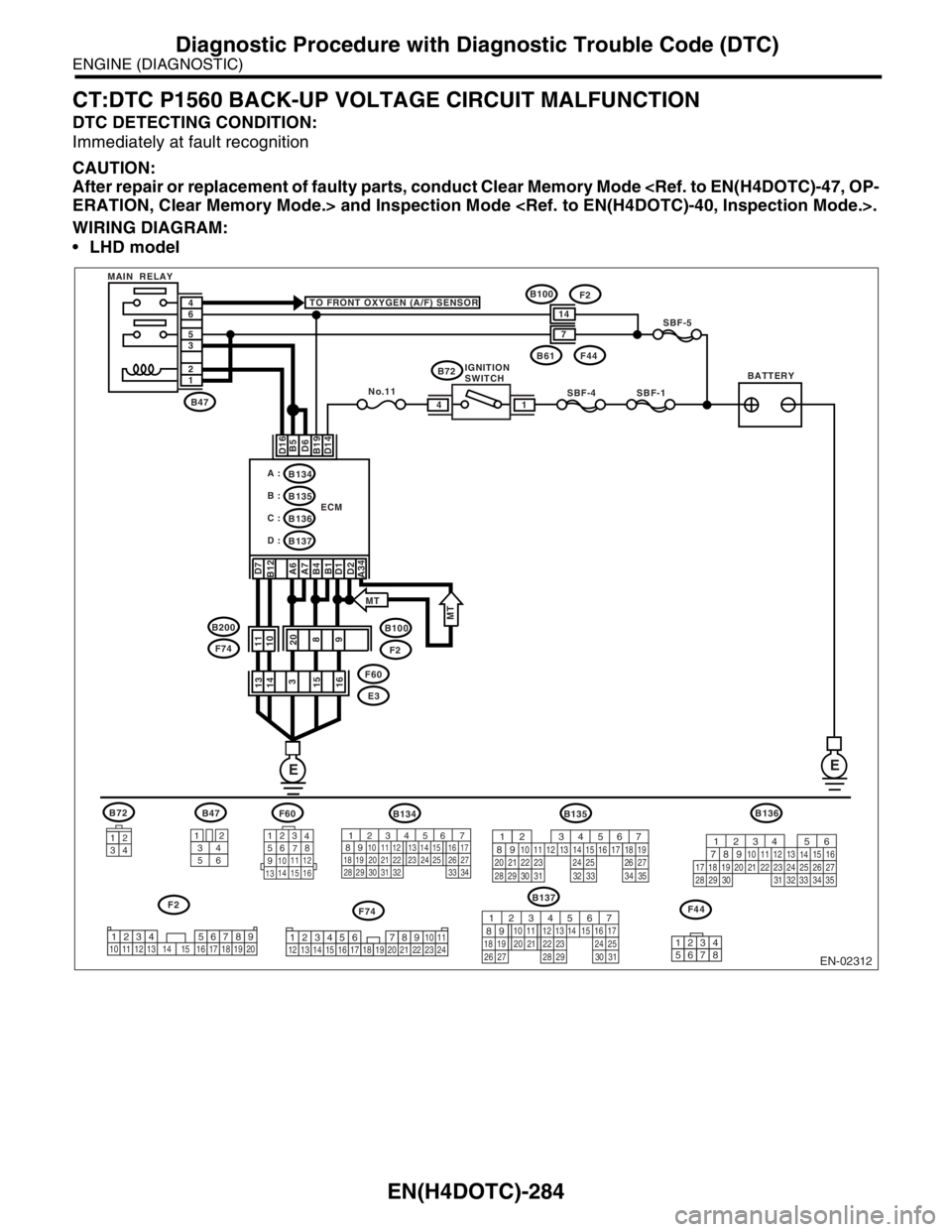
CT:DTC P1560 BACK-UP VOLTAGE CIRCUIT MALFUNCTION
DTC DETECTING CONDITION:
Immediately at fault recognition
CAUTION:
After repair or replacement of faulty parts, conduct Clear Memory Mode
ERATION, Clear Memory Mode.> and Inspection Mode .
WIRING DIAGRAM:
LHD model
EN-02312
F74
B72
34
12
BATTERYIGNITION
SWITCH MAIN RELAY
SBF-4SBF-1
SBF-5
B72 TO FRONT OXYGEN (A/F) SENSOR
D16 D7
B12
A6
A7
B4
B1
D1
D2
A34B5
D6
B19
D14
No.11
B61F44
B47
B100
F2
E3 F60 1 2 3 5 6 4
ECM
EE
14
B134
B137 B135 A :
B :
C :B136
D :
14
7
3412
56
123
4
56
78
9
1011 12
1314 15 16
F60B47
B137
F2
B100F2
11
10
20
8
9 13
14
3
15
16
B135
F44
567
82 1
94 310
24 22 23 2511 12 13 14 15
26 27
2816 17 18 19
20 21
29 30 31 32 33 34 35
12345678
34
12 8910 11
12 13 14 15 16 17 18 19 20 21 22 23 2456 71234 5678910 11 12 13 14 15 16 17 18 19 20
567
82 1
94 310
22 23 11 12 13 14 15
24 25
2616 17
18 19 20 21
27 28 29 30 31
F74 B200
MT
MT
B134
56 7
82 1
94 310
24 22 23 25 11 12 13 14 15
26 27
2816 17
18 19 20 21
33 34 29
32 30 31
B136
56
782 1
94 310
24 22 23 2511 12 13
1415
26 27
2816
17 18 19 20 21
33 34 29
32 30
31 35
Page 1942 of 2870

FU(H4DOTC 2.5)-12
FUEL INJECTION (FUEL SYSTEM)
General Description
C: CAUTION
Wear working clothing, including a cap, protec-
tive goggles, and protective shoes during opera-
tion.
Remove contamination including dirt and corro-
sion before removal, installation or disassembly.
Keep the disassembled parts in order and pro-
tect them from dust or dirt.
Before removal, installation or disassembly, be
sure to clarify the failure. Avoid unnecessary re-
moval, installation, disassembly, and replacement. Be careful not to burn yourself, because each
part on the vehicle is hot after running.
Be sure to tighten fasteners including bolts and
nuts to the specified torque.
Place shop jacks or rigid racks at the specified
points.
Before disconnecting electrical connectors of
sensors or units, be sure to disconnect negative
terminal from battery.
Place “NO FIRE” signs near the working area.
Be careful not to spill fuel on the floor.
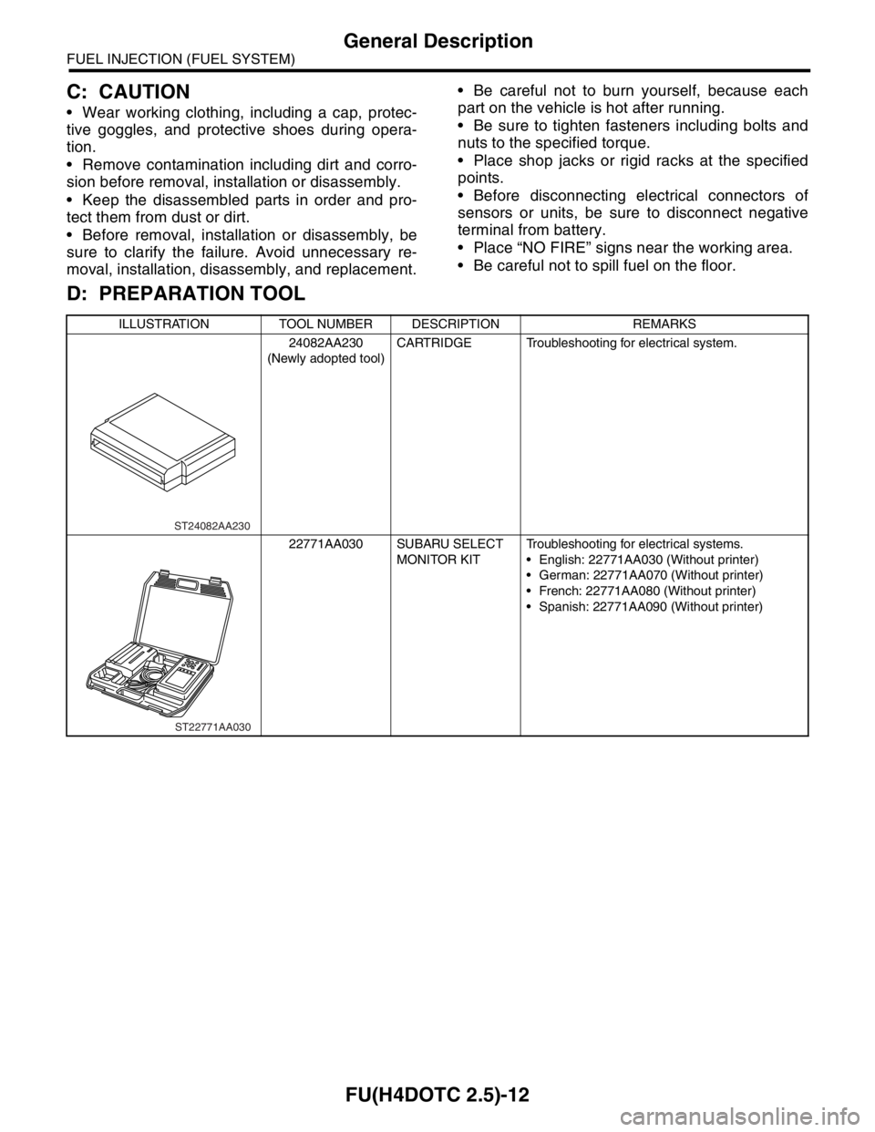
D: PREPARATION TOOL
ILLUSTRATION TOOL NUMBER DESCRIPTION REMARKS
24082AA230
(Newly adopted tool)CARTRIDGE Troubleshooting for electrical system.
22771AA030 SUBARU SELECT
MONITOR KITTroubleshooting for electrical systems.
English: 22771AA030 (Without printer)
German: 22771AA070 (Without printer)
French: 22771AA080 (Without printer)
Spanish: 22771AA090 (Without printer)
ST24082AA230
ST22771AA030
Page 2016 of 2870
SP(H4DOTC 2.5)-3
SPEED CONTROL SYSTEM
General Description
C: CAUTION
Wear work clothing, including a cap, protective
goggles, and protective shoes during operation.
Remove contamination, including dirt and corro-
sion, before removal, installation or disassembly.
Keep the disassembled parts in order and pro-
tect them from dust and dirt.
Before removal, installation or disassembly, be
sure to clarify the failure. Avoid unnecessary re-
moval, installation, disassembly, and replacement.
Be careful not to burn your hands, because each
part in the vehicle is hot after running.
Be sure to tighten fasteners including bolts and
nuts to the specified torque.
Place shop jacks or rigid racks at the specified
points.
Before disconnecting electrical connectors of
sensors or units, be sure to disconnect the ground
cable from battery.
Page 2079 of 2870
EN(H4DOTC 2.5)-55
ENGINE (DIAGNOSTIC)
Diagnostics for Engine Starting Failure
B: STARTER MOTOR CIRCUIT
CAUTION:
After repair or replacement of faulty parts, conduct Clear Memory Mode
OPERATION, Clear Memory Mode.> and Inspection Mode
Inspection Mode.>.
WIRING DIAGRAM:
EN-02311
BATTERY
INHIBITOR SWITCH
IGNITION
SWITCH
STARTER
MOTOR
SBF-4SBF-1
B72
B72
B14
B137
ECM
EE
1
3
D8
3412
B137
T3B12MT
AT
AT
MT
1112712
PR
N
D3
21
T7
B12
123
8
9
10
4
11
1256
7
T7
123
8910411 1256
7567
82 1
94 310
22 23 11 12 13 14 15
24 25
2616 17
18 19 20 21
27 28 29 30 31
Page 2081 of 2870
EN(H4DOTC 2.5)-57
ENGINE (DIAGNOSTIC)
Diagnostics for Engine Starting Failure
C: CHECK POWER SUPPLY AND GROUND LINE OF ENGINE CONTROL MOD-
ULE (ECM)
CAUTION:
After repair or replacement of faulty parts, conduct Clear Memory Mode
OPERATION, Clear Memory Mode.> and Inspection Mode
Inspection Mode.>.
WIRING DIAGRAM:
EN-02356
B72
B135
3412
BATTERY MAIN RELAY
SBF-4 SBF-1SBF-5
B72
D16 D7
B12
A6
A7
B1
B4
D1
D2
A34B5
B6
B19
D14
No.11
B47
E2 B21 1 2 3 5 6 4
ECM
E
E
1 4
B134
B135
B137 A:
B:
D:
14133
15
16
34 12
56123
4
56
78
91011 12
1314 15 16
B134 B21 B47B137 A: D:
B: IGNITION
SWITCH
56 7
82 1
94 310
24 22 23 25 11 12 13 14 15
26 27
2816 17
18 19 20 21
33 34 29
32 30 31
567
82 1
94 310
24 22 23 2511 12 13 14 15
26 27
2816 17 18 19
20 21
29 30 31 32 33 34 35
567
82 1
94 310
22 23 11 12 13 14 15
24 25
2616 17
18 19 20 21
27 28 29 30 31